Filtration System Critical Design Features
1. Introduction
Filtration and ultrafiltration systems are integrated assemblies of mechanical components, fluid handling elements, sensors, and control logic designed to deliver controlled separation performance under GMP conditions.
While system architecture defines configuration, component design determines how the system actually behaves during operation. Membrane performance, fouling behavior, pressure stability, cleanability, and data integrity are all governed at the component level.
This article explains the functional role of each major system element and identifies design features that directly influence performance, contamination control, and qualification strategy.
2. Membrane Modules and Separation Function
2.1 Functional Role of the Membrane
The membrane is the active separation element. It determines what passes and what is retained.
- In sterile filtration, the membrane retains microorganisms and particulates based on pore size.
- In ultrafiltration, the membrane retains macromolecules based on molecular weight cut-off.
- In viral filtration, retention depends on defined size exclusion mechanisms and validated retention claims.
Membrane performance is governed by:
• Effective surface area
• Pore structure
• Flow regime
• Transmembrane pressure
• Product viscosity
As material accumulates on or within a membrane during filtration, a condition known as fouling, permeate flow decreases and system pressures change. For this reason, proper membrane selection and sizing are critical to achieving stable and predictable performance.
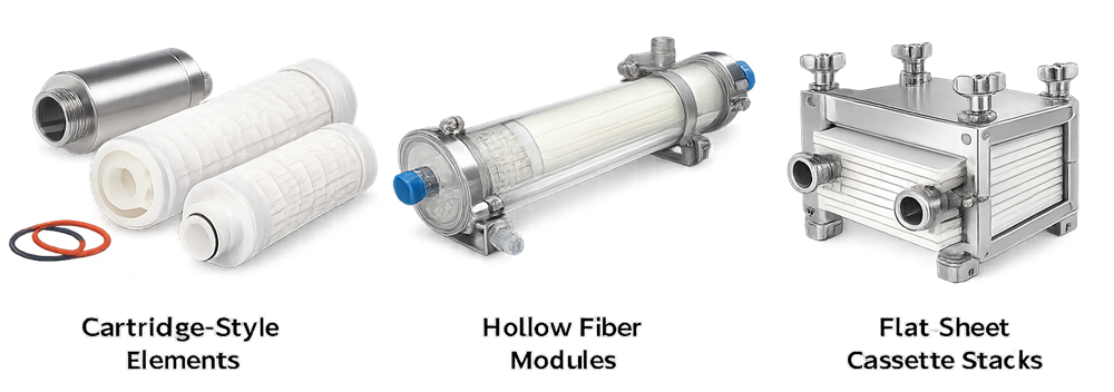
2.2 Module Configuration
Membranes are packaged into modules whose geometry determines hydraulic behavior, available surface area, scalability, and cleanability. Common configurations include cartridge-style elements, hollow fiber modules, and flat-sheet cassette stacks. Hollow fiber systems provide high surface area within a compact cylindrical format and are widely used in biologics processing. Flat-sheet cassette systems enable modular scale-up by stacking membrane plates within a compression holder. The image below compares these three configurations used in pharmaceutical filtration systems.
Module geometry influences:
• Flow distribution
• Channel shear
• Fouling rate
• Cleanability
• Pressure drop
Improper module selection leads to unstable flux, excessive ΔP, or rapid fouling.
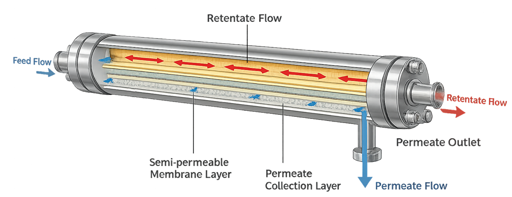
The internal structure of a tangential flow filtration module determines flow distribution, shear conditions, and permeation behavior. The cross-section below illustrates retentate flow channels, membrane layers, and permeate collection pathways within a typical module.
3. Housing Design and Mechanical Integrity
The housing provides structural containment and defines sanitary integrity. Its functions include:
• Maintaining pressure envelope
• Directing flow paths
• Supporting venting and draining
• Enabling CIP and SIP
Critical design features:
• 316L stainless steel construction
• Surface finish compatible with cleanability
• Proper weld quality
• Sanitary connection design
• Proper vent and drain placement
Housing geometry must eliminate stagnant zones. Dead legs and poorly sloped piping introduce microbial and endotoxin risk. Mechanical design must withstand:
• Maximum operating pressure
• Steam sterilization temperature
• Pressure cycling
Housing integrity directly impacts sterility assurance and validation scope.
4. Pumping System and Flow Control
4.1 Functional Role of the Pump
The pump provides the driving force for fluid movement through the system.
In normal flow filtration, it controls feed rate.
In TFF systems, it maintains crossflow velocity and stabilizes transmembrane pressure.
Pump performance influences:
• Shear exposure
• Residence time
• Heat generation
• Flow stability
Unstable pump control results in fluctuating TMP and inconsistent permeate flux.
4.2 Pump Selection Considerations
Peristaltic pumps offer gentle handling but may introduce pulsation.
Centrifugal pumps provide stable flow but may increase shear.
Diaphragm pumps provide sanitary isolation but require proper control tuning.
Design must ensure:
• Adequate NPSH (Net Positive Suction Head)
• Cavitation prevention
• Cleanability
• Compatibility with product chemistry
In TFF systems, the recirculation pump is central to system stability. Its sizing must support required crossflow without exceeding membrane pressure limits.
5. Pressure Measurement and Control
5.1 Functional Importance of Pressure Monitoring
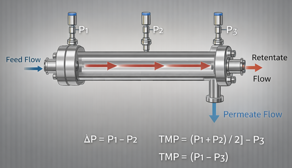
Pressure monitoring enables calculation of:
ΔP = P1 − P2
TMP = [(P1 + P2) / 2] − P3
ΔP indicates axial resistance along the retentate channel.
TMP represents the effective driving force across the membrane.
Both are critical to:
• Flux control
• Fouling detection
• Process stability
• Alarm protection
Accurate calculation of axial pressure drop and transmembrane pressure requires defined sensor placement. The diagram below shows proper positioning of P1, P2, and P3 relative to the membrane module.
5.2 Sensor Placement and Design
Pressure sensors must be positioned:
• At module inlet
• At module outlet
• At permeate line
Improper placement yields inaccurate TMP calculation. Transmitters must be:
• Sanitary diaphragm type
• Calibrated
• Temperature compatible
• Protected against steam damage
Instrumentation design directly affects control capability.
6. Flow Measurement and Mass Balance
Flow meters provide quantitative process control. Functional roles include:
• Monitoring permeate flux
• Calculating volume reduction factor
• Controlling diafiltration
• Supporting mass balance verification
Inadequate flow measurement results in:
• Uncontrolled concentration endpoints
• Inconsistent diafiltration
• Poor batch reproducibility
Flow meter selection must consider viscosity, cleanability, and pressure rating.
7. Valve Configuration and Routing Logic
Valves define how fluid is routed through the filtration system during:
• Processing
• Cleaning
• Sterilization
• Drainage
Valve design and control strategy are critical to maintaining product integrity and preventing cross-contamination. Improper routing can contaminate permeate, introduce cleaning solution into product lines, or compromise sterility boundaries.
7.1 Valve Functional Definitions
Each valve serves a defined routing or isolation function within the system.
| Valve | Functional Role | Typical Fail Position |
|---|---|---|
| V1 | Feed isolation to module inlet | Closed |
| V2 | Retentate loop isolation | Closed |
| V3 | Permeate outlet isolation | Closed |
| V4 | CIP supply isolation | Closed |
| V5 | Drain to waste | Closed |
Fail-closed configuration is typically preferred unless risk assessment justifies an alternative state.
Valve placement must minimize internal hold-up volume and avoid dead legs that may compromise cleanability.
7.2 Valve Position Matrix
Operational modes require specific valve configurations. These positions must be interlocked within the control system to prevent incompatible routing states.
| Mode | V1 | V2 | V3 | V4 | V5 | Functional Description |
|---|---|---|---|---|---|---|
| Process | Open | Open | Open | Closed | Closed | Product flows to module; retentate recirculates; permeate collected |
| CIP | Closed | Open | Closed | Open | Open | Cleaning solution circulates through module; drains to waste |
| Sterilization (if applicable) | Closed | Open | Closed | Closed | Open | Steam path through module; condensate drains |
| Drain | Closed | Closed | Closed | Closed | Open | System fully drained |
The matrix must be formally documented within the control strategy and verified during operational qualification.
7.3 Control and Interlock Considerations
Automation logic must prevent:
• Simultaneous opening of feed and CIP supply
• Routing permeate to waste during product collection
• Backflow from waste to process lines
• Incomplete isolation during sterilization
Valve sequencing must be validated during OQ to demonstrate:
• Correct response to command
• Proper fail-safe behavior
• Alarm generation for misrouting
• Interlock enforcement
Valve misrouting is a process risk, not merely a mechanical issue. Clear routing documentation combined with validated automation logic ensures repeatable and contamination-free operation.
8. Cleaning and Sterilization Integration
Reusable TFF systems must be engineered to support validated cleaning and sterilization without reliance on manual intervention or disassembly. The piping, valve arrangement, elevation changes, and utility tie-ins must collectively enable controlled CIP and SIP execution under reproducible and documented conditions. Critical design considerations include:
• Adequate CIP spray coverage or turbulent flow velocity through all wetted paths
• Proper line slope toward defined low points to ensure complete drainage
• Uniform steam distribution across all product-contact surfaces
• Effective air removal during SIP to prevent insulating air pockets
• Continuous condensate evacuation during steam exposure
Cold spots, stagnant regions, or trapped condensate compromise lethality and invalidate sterilization assumptions. Therefore, mechanical design must prevent horizontal dead legs, unvented high points, and untrapped condensate pockets.
8.1 CIP Integration Concept
During CIP, cleaning solution is introduced from a dedicated CIP supply header through a defined isolation valve upstream of the TFF module. The cleaning fluid flows through the same wetted path used during processing, including the feed inlet, module channels, retentate loop, and permeate circuit if required by the cleaning strategy. All process isolation valves must be positioned to ensure that cleaning solution contacts every internal surface subject to product exposure.
The return path is routed to a CIP return header, allowing recirculation to the CIP skid. This return path must be hydraulically defined and segregated from process discharge and drain-to-waste lines. Sampling ports for rinse verification are positioned on the CIP return line, not on drain legs, to allow representative conductivity, TOC, or residue monitoring.
All non-cleaning pathways must remain isolatable during CIP to prevent cross-contamination between process and cleaning utilities.
8.2 Drainage Architecture
The system must incorporate defined low points with slope, typically not less than 1 percent, toward a dedicated drain header. The drain header is reserved exclusively for disposal and post-cleaning evacuation. It must not function as a product or permeate line.
Each low point requires a drain valve that permits complete emptying of the module, retentate loop, permeate leg, and any vertical drops. Drain geometry must avoid liquid pooling and support gravity evacuation following CIP or SIP.
8.3 SIP Integration Concept
Steam-in-place utilizes the same wetted process path but substitutes cleaning solution with saturated steam introduced through a controlled steam supply connection. Steam must enter at a location that promotes full displacement of residual air. High-point vents are mandatory to remove non-condensable gases prior to achieving sterilization temperature.
Low-point condensate outlets must be equipped with properly sized steam traps to continuously evacuate condensate during exposure. Inadequate condensate removal leads to localized temperature depression and sterilization failure.
The SIP circuit must be capable of achieving uniform temperature across the TFF module and all associated piping. Vent, trap, and isolation valve placement must prevent cold zones and allow temperature mapping during validation.
Validation Expectations
8.4 Validation Expectations
CIP and SIP design must allow:
• Demonstration of full surface coverage
• Verification of drainage completeness
• Temperature mapping and air removal confirmation
• Reproducible cycle execution under defined valve configurations
Mechanical design is inseparable from validation strategy. The piping geometry, utility tie-ins, venting, and drainage define whether the system can consistently achieve decontamination targets. Reproducibility depends not only on cycle parameters but on the physical architecture that supports them.
9. Control System Functionality
The control system integrates sensors, pumps, and valves into a stable operating platform. Functional responsibilities include:
• Maintaining TMP within limits
• Alarm generation
• Data logging
• Interlock protection
• Automated sequencing
Poor control design results in process variability and validation difficulty. Control architecture must support:
• Defined alarm limits
• Access control
• Audit trail integrity where applicable
10. Materials of Construction
Materials influence chemical compatibility and extractables risk. Common materials include:
• 316L stainless steel
• EPDM or PTFE seals
• Silicone tubing
• Polyethersulfone membranes
Material selection must account for:
• Product chemistry
• Cleaning agents
• Sterilization conditions
• Pressure stress
Material incompatibility can lead to swelling, leaching, or premature failure.
11. Expanded Relationship to Qualification
Component design determines qualification depth and strategy.
Installation Qualification must verify:
• Correct installation of modules and housings
• Proper weld documentation
• Material traceability
• Instrument calibration status
Operational Qualification must demonstrate:
• Accurate pressure measurement
• Stable pump control
• Proper valve sequencing
• Alarm functionality
• TMP control response
Performance Qualification evaluates:
• Flux stability
• Fouling behavior
• Process repeatability
• Cleaning and sterilization effectiveness
Qualification cannot compensate for flawed component design. If:
• Sensors are poorly located
• Pumps are undersized
• Dead legs are excessive
• Valves create hold-up zones
Validation cannot compensate for flawed engineering. In that case, validation activities are used to correct design weaknesses instead of confirming proper system performance. Engineering robustness reduces qualification complexity and lifecycle risk.
12. Conclusion
System performance is not determined solely by membrane selection but by the integrated behavior of pumps, housings, instrumentation, valves, materials, and control logic. Each component contributes to:
• Process stability
• Contamination control
• Data integrity
• Cleanability
• Regulatory compliance
Sound engineering design establishes the operational envelope within which validation confirms fitness for intended use.