

Dry Heat Sterilization Systems and Principles
Dry heat sterilization uses controlled exposure to heated air to inactivate viable microorganisms on heat-stable materials. Unlike moist heat sterilization, it does not depend on saturated steam contacting the load. Heat must be transferred from the surrounding air through the item, package, container, or material until the most difficult-to-heat location receives the required microbial lethality.
The process may be performed in:
- Static-air batch ovens
- Forced-air circulation batch ovens
- Continuous dry-heat tunnels
Dry heat is most appropriate when the load can tolerate the required temperature and when moisture would be undesirable or incompatible with the material. Typical applications include glassware, stainless-steel parts, heat-stable instruments, certain powders, oils, and other nonaqueous materials.
Dry heat sterilization and dry heat depyrogenation are related thermal technologies, but they have different targets, acceptance endpoints, and validation strategies. Sterilization addresses viable microorganisms. Depyrogenation addresses bacterial endotoxins. The two claims should not be treated as interchangeable.
Purpose and Scope
This article explains:
- Dry heat microbial-inactivation principles
- Heat-transfer mechanisms
- Static and forced-air batch ovens
- Continuous dry-heat tunnels
- Heating, exposure, cooling, and unloading
- Airflow and temperature distribution
- Load and material compatibility
- Load configuration
- Cycle-development strategy
- Critical operating parameters
- Routine process control
- The boundary between sterilization and depyrogenation
- The lifecycle relationship between process development and qualification
Detailed IQ, OQ, PQ, temperature mapping, biological-indicator studies, and requalification requirements are addressed in Dry Heat Qualification.
Scientific Basis of Dry Heat Sterilization
Dry heat causes irreversible damage to microbial cells and spores through a combination of mechanisms that may include:
- Oxidative damage to cellular constituents
- Protein denaturation
- Membrane damage
- Nucleic-acid damage
- Desiccation-related effects
- Loss of essential metabolic function
The relative contribution of each mechanism depends on the microorganism, temperature, exposure time, surrounding material, water activity, and process conditions.
Dry heat generally produces microbial inactivation more slowly than saturated steam at comparable temperatures. Moist heat transfers energy efficiently through condensation and promotes protein denaturation in the presence of water. Dry air has lower heat-transfer capability and does not provide the same moisture-assisted inactivation mechanism.
Consequently, dry heat processes normally require:
- Higher temperatures
- Longer exposure
- Careful control of temperature distribution
- Adequate heat penetration into the load
- Material compatibility with the complete thermal exposure
Published temperature-and-time combinations may be useful during preliminary development, but they are not universal GMP cycles. The approved cycle must be supported by the actual equipment, load, microbial challenge, heat-transfer characteristics, operating range, and required sterility-assurance objective.
Microbial Lethality and Resistance
Dry heat sterilization is governed by the same general kinetic concepts used for other sterilization processes, including:
- Initial microbial population
- Microbial resistance
- Logarithmic population reduction
- D-value
- z-value
- Accumulated lethality
- Sterility assurance level
- Process variability
- Worst-case exposure
The D-value represents the time required under specified conditions to reduce a microbial population by one log₁₀. A dry-heat D-value is meaningful only when its temperature, test material, carrier, recovery method, and other relevant conditions are identified.
The z-value represents the temperature change required to change the D-value by a factor of ten. It provides a basis for relating microbial lethality delivered at different temperatures, provided the selected kinetic model is appropriate.
Equivalent dry-heat exposure may be expressed as:
F(Tref) = ∫ 10^[(T(t) − Tref) / z] dt
where:
- F(Tref) is the equivalent exposure time at the selected reference temperature
- T(t) is the measured temperature at time t
- Tref is the justified reference temperature
- z is the temperature change required to change the microbial D-value by a factor of ten
- dt is the incremental time interval over which lethality is accumulated
For a practical calculation using recorded temperatures:
F(Tref) ≈ Σ 10^[(Ti − Tref) / z] × Δt
where:
- Ti is the measured temperature during interval i
- Δt is the data-recording interval
- The units of F(Tref) are the same as the units used for Δt, normally minutes
The selected reference temperature and z-value must be stated. They should not be assumed from another process or copied from a depyrogenation study without demonstrating applicability.
A calculated lethality value does not independently prove sterilization. The calculation remains dependent on:
- Appropriate microbial resistance data
- Representative temperature measurements
- Correct sensor locations
- Adequate heat penetration
- Validated load configuration
- Accurate time measurement
- Appropriate calculation boundaries
- Reproducible equipment performance
- Control of routine operating parameters
The relationship among microbial population, D-value, z-value, lethality, and SAL is addressed in Sterility Assurance Level and Sterilization Kinetics.
Sterilization Versus Depyrogenation
Dry heat may support either sterilization or depyrogenation, and sufficiently severe depyrogenation exposure will generally also render an item sterile. That fact does not make the validation claims identical.
| Attribute | Dry heat sterilization | Dry heat depyrogenation |
|---|---|---|
| Primary target | Viable microorganisms, including resistant spores | Bacterial endotoxins |
| Process objective | Defined microbial inactivation and sterility assurance | Defined endotoxin inactivation or removal |
| Typical challenge | Bioburden or resistant biological indicator | Endotoxin challenge |
| Principal endpoint | Microbial lethality or justified SAL | Demonstrated endotoxin log reduction |
| Primary evidence | Physical measurements, heat penetration, microbial resistance, BI or bioburden evidence | Physical measurements, endotoxin challenge, recovery controls, and log-reduction evidence |
| Routine control | Validated time, temperature, airflow, load, and equipment parameters | Validated time, temperature, belt speed, load presentation, airflow, and other applicable parameters |
| Main failure concern | Inadequate heat exposure at a microbial worst case | Inadequate endotoxin reduction at the worst-case item or location |
A sterile item is not necessarily nonpyrogenic. Sterilization conditions may inactivate microorganisms without providing the more severe exposure needed to achieve the required endotoxin reduction.
Conversely, an adequately validated dry-heat depyrogenation process may deliver more than sufficient microbial lethality. FDA’s aseptic-processing guidance states that when the applicable dry-heat depyrogenation process has demonstrated the specified endotoxin reduction, a separate biological-indicator sterilization challenge may not be indicated. This conclusion applies to that validated process and should not be generalized to lower-temperature sterilization cycles.
Detailed depyrogenation science and equipment considerations are addressed in Depyrogenation Equipment and Process Design. Endotoxin challenge studies are addressed in Depyrogenation Validation and Qualification.
Dry Heat Equipment Types
Dry heat systems differ significantly in airflow, loading, heat transfer, material movement, cooling, and sterile-boundary control.
Static-Air Batch Ovens
Static-air ovens depend principally on natural convection and radiant heat transfer. Heated air rises, cooler air descends, and the resulting circulation distributes heat through the chamber.
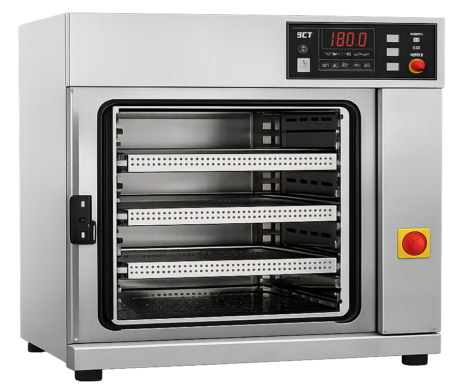
Typical applications include:
- Laboratory glassware
- Small metal tools
- Heat-stable instruments
- Small component loads
- Limited-scale production materials
Principal design characteristics may include:
- Insulated stainless-steel chamber
- Shelves, trays, or racks
- Electrical heating elements
- Natural convection
- Temperature controller
- Independent monitoring sensor
- Cycle timer
- Overtemperature protection
- Single-door or pass-through construction
Static ovens are mechanically simple, but they may be more susceptible to:
- Temperature stratification
- Slow heat-up
- Shelf-to-shelf variation
- Door-adjacent cold locations
- Localized radiant heating
- Load-dependent heat distribution
- Extended cooling periods
A chamber-temperature display does not establish that every load location has received the required exposure.
Forced-Air Circulation Ovens
Forced-air ovens use one or more fans to circulate heated air through the chamber and around the load.
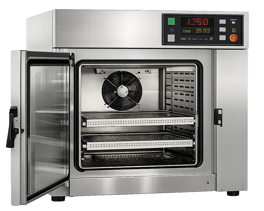
Potential advantages include:
- Improved temperature uniformity
- Faster heat transfer
- Reduced stratification
- Shorter heating and cooling periods
- Improved support for larger chambers
- Better control of complex loads
The circulation system also introduces additional dependencies:
- Fan operation
- Fan direction and speed
- Air-supply and return paths
- Dampers
- Heating-element arrangement
- Airflow obstruction
- Filter resistance
- Control interlocks
- Alarm response
High air velocity does not automatically provide uniform exposure. Poorly positioned loads may block supply or return paths, create localized recirculation, or cause channeling through open areas while shielded items heat slowly.
Continuous Dry Heat Tunnels
Continuous dry-heat tunnels convey items through separately controlled process zones. They are frequently integrated between container washing and aseptic filling operations.
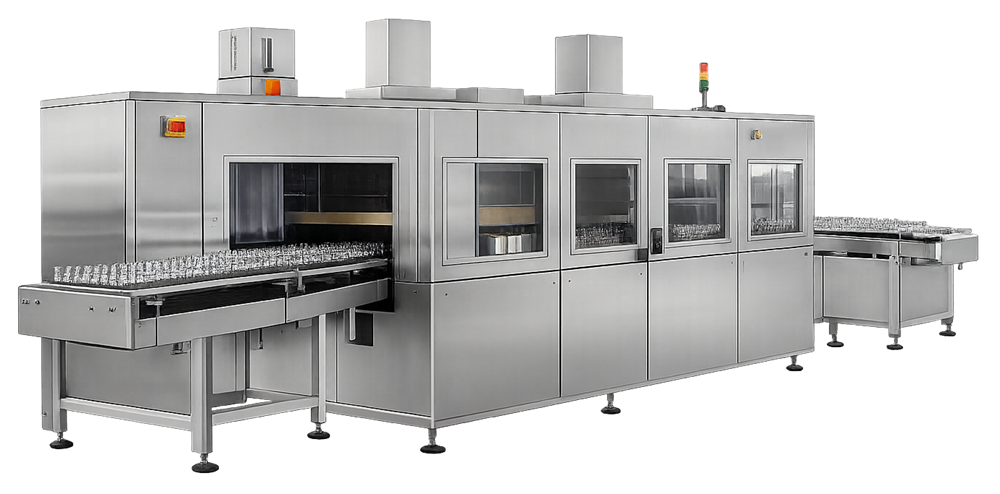
A tunnel commonly includes:
- An infeed or preheating zone
- A high-temperature treatment zone
- A controlled cooling zone
- A discharge interface with the filling line
Potential applications include:
- Glass vials
- Ampoules
- Cartridges
- Other heat-resistant containers
Critical tunnel functions include:
- Conveyor speed
- Zone temperatures
- Airflow direction and balance
- HEPA-filtered air supply where required
- Container presentation and density
- Heating-zone residence time
- Cooling-zone performance
- Pressure relationships
- Alarm and rejection logic
- Protection of the sterile discharge boundary
- Integration with upstream washing and downstream filling
A tunnel is not merely a long oven. Its performance depends on the interaction of temperature, conveyor movement, container mass, airflow, zone transitions, cooling, and line integration.
Batch Oven and Continuous Tunnel Comparison
| Characteristic | Batch oven | Continuous tunnel |
|---|---|---|
| Processing mode | Defined load processed through one complete cycle | Continuous container movement through sequential zones |
| Typical load | Components, tools, glassware, powders, oils, or assembled loads | Uniform containers such as vials, ampoules, or cartridges |
| Material movement | Load remains stationary during processing | Conveyor transports items continuously |
| Heating control | Chamber temperature and cycle time | Zone temperatures and conveyor residence time |
| Exposure determination | Time after defined exposure conditions are established | Time within the qualified high-temperature zone |
| Airflow concern | Distribution around shelves, racks, trays, and load | Zone balance, directional airflow, container-bed penetration, and discharge protection |
| Cooling | Usually part of the batch cycle before unloading | Dedicated cooling zone before filling-line transfer |
| Sterile transfer | Manual or controlled transfer after unloading | Direct integration with the filling line |
| Principal load variable | Load mass, arrangement, orientation, and airflow obstruction | Container size, mass, spacing, density, line speed, and belt presentation |
| Typical control risk | Cold spots, stratification, blocked airflow, or premature exposure timing | Belt-speed variation, zone instability, airflow imbalance, stoppage, or boundary failure |
| Typical use | Sterilization or depyrogenation, depending on validated cycle | Commonly container depyrogenation with accompanying sterilization |
| Qualification emphasis | Empty and loaded distribution, heat penetration, and cycle reproducibility | Zone mapping, container penetration, belt speed, airflow, cooling, and line integration |
Heat-Transfer Mechanisms
Heat reaches the load through three mechanisms.
Convection
Convection transfers heat from circulating air to exposed item surfaces. Its effectiveness depends on:
- Air temperature
- Air velocity
- Airflow direction
- Surface exposure
- Load arrangement
- Boundary-layer conditions
- Obstructions
- Air density and system design
Forced convection generally improves heat transfer, but only when air reaches the relevant surfaces.
Conduction
After the item surface heats, thermal energy moves through the material by conduction. The rate depends on:
- Material thermal conductivity
- Item thickness
- Mass
- Geometry
- Contact between items
- Packaging
- Internal cavities
- Fill depth
- Initial temperature
A large metal assembly may conduct heat differently from a tray of small tools. A powder bed may insulate its interior even when the container surface rapidly reaches chamber temperature.
Radiation
Heating elements and hot chamber surfaces may transfer energy by thermal radiation. Radiant exposure can contribute significantly at high temperatures and may cause surfaces facing the heat source to warm faster than shielded locations.
The relative contributions of convection, conduction, and radiation can change with load position. Cycle development must evaluate the complete loaded configuration rather than relying only on chamber-air temperature.
Heating Phase
The heating phase begins when the equipment applies thermal energy and continues until the defined exposure-start conditions are met.
Heating performance may be affected by:
- Equipment starting temperature
- Load starting temperature
- Load mass
- Material heat capacity
- Shelf or rack location
- Airflow
- Heater capacity
- Fan performance
- Door-seal integrity
- Control-sensor location
- Chamber leakage
- Ambient conditions
- Tunnel conveyor speed
- Container density
The controller may reach setpoint before the slowest-heating load location reaches its required temperature. Exposure time should therefore begin according to a validated control strategy that represents adequate establishment of the required conditions—not merely when one chamber sensor first reaches setpoint.
Potential exposure-start approaches include:
- Defined chamber-equilibration criteria
- Confirmed attainment of a validated control condition
- Recipe logic demonstrated to correlate with the slowest-heating load location
- A justified fixed delay after chamber setpoint is reached
The selected approach must remain consistent with the qualification evidence.
Exposure Phase
During exposure, the process must maintain the conditions required to deliver the specified microbial lethality. The control strategy should address:
- Minimum temperature
- Maximum temperature
- Exposure duration
- Permitted temperature variation
- Control stability
- Air circulation
- Fan status
- Conveyor speed for tunnels
- Zone conditions
- Alarm limits
- Data-recording interval
- Required load configuration
- Conditions that invalidate or interrupt exposure
The process must control both underexposure and excessive exposure. Underexposure may result in insufficient microbial lethality. Excessive exposure may cause:
- Material degradation
- Discoloration
- Oxidation
- Loss of mechanical properties
- Container deformation
- Lubricant deterioration
- Seal damage
- Increased particulate generation
- Reduced component life
- Unacceptable product-quality effects
The approved operating range should provide adequate lethality while remaining within demonstrated material-compatibility limits.
Cooling Phase
Cooling is part of the controlled process, particularly when the processed item must remain sterile until use.
Cooling may be passive or forced. The strategy should consider:
- Cooling rate
- Filtered-air requirements
- Airflow direction
- Chamber pressure
- Door-opening criteria
- Item temperature at unloading
- Operator safety
- Thermal shock
- Container breakage
- Condensation after transfer
- Recontamination risk
- Maximum permitted post-cycle hold time
Opening a batch oven before the approved unloading condition may compromise sterile items or expose operators to unsafe temperatures. In a continuous tunnel, the cooling zone must reduce container temperature without compromising the sterile boundary. Its performance is connected to:
- HEPA-filtered airflow
- Pressure relationships
- Cooling capacity
- Conveyor speed
- Container density
- Tunnel discharge conditions
- Filling-line operation
Stopping or slowing the conveyor may increase thermal exposure in one zone while reducing process continuity elsewhere. Tunnel stoppage and restart logic must therefore be defined during development.
Airflow and Temperature Distribution
Airflow is a fundamental process variable because it affects:
- Heat delivery
- Temperature uniformity
- Heating rate
- Cold-spot location
- Cooling
- Particulate control
- Pressure relationships
- Sterile-boundary protection
For batch ovens, airflow may be disturbed by:
- Overloaded shelves
- Large solid trays
- Closed containers
- Nested components
- Closely packed parts
- Items placed against chamber walls
- Blocked supply openings
- Blocked return openings
- Incorrect rack location
- Fan deterioration
- Filter loading
- Unapproved load arrangements
For tunnels, airflow must be evaluated within and between zones. Excessive or incorrectly directed air may disturb containers or transfer particles. Insufficient airflow may produce localized temperature variation or weaken the sterile interface.
Airflow direction should support the intended contamination-control strategy. The highest-temperature zone does not automatically require the highest pressure. Zone pressures and air movement must be designed to protect the processed containers, control heat migration, and maintain the interface with the filling environment.
Airflow behavior should be considered under:
- Normal steady-state operation
- Startup
- Shutdown
- Conveyor stoppage
- Fan failure
- Filter loading
- Door opening
- Upstream equipment interruption
- Downstream filling-line interruption
Load Compatibility
A material may be heat stable at the target temperature but still be unsuitable for the complete process. Compatibility assessment should consider:
- Maximum temperature
- Total thermal exposure
- Repeated exposure
- Oxidation
- Embrittlement
- Melting or softening
- Dimensional change
- Surface deterioration
- Lubricant stability
- Coating stability
- Adhesive stability
- Package integrity
- Particulate generation
- Chemical degradation
- Functional performance after processing
- Cooling and thermal-shock effects
Commonly compatible materials may include:
- Borosilicate glass
- Certain stainless-steel components
- Heat-resistant metal tools
- Some mineral oils
- Some anhydrous powders
- Selected ceramics
Materials frequently requiring additional evaluation or another sterilization method include:
- Elastomers
- Many plastics
- Electronic assemblies
- Moisture-containing products
- Heat-sensitive chemicals
- Cellulosic materials
- Adhesive-bonded assemblies
- Components with temperature-sensitive coatings
- Sealed items that may develop pressure
Compatibility conclusions should be supported by the actual cycle, not solely by a supplier’s general maximum-temperature rating.
Powders, Oils, and Nonaqueous Materials
Powders and oils require particular attention because they may heat slowly and nonuniformly. Relevant variables include:
- Batch mass
- Fill depth
- Container geometry
- Material density
- Particle size
- Bulk packing
- Thermal conductivity
- Initial temperature
- Moisture content
- Oil viscosity
- Container closure
- Air space
- Location within the oven
FDA’s aseptic-processing guidance identifies carefully designed heat-distribution and heat-penetration studies as particularly important for powders because of their insulating effects. A powder-container surface temperature does not establish that the interior has received adequate exposure. FDA’s aseptic-processing guidance addresses this concern directly.
Cycle development should also assess whether dry heat adversely changes the material’s:
- Chemical identity
- Potency
- Purity
- Particle characteristics
- Solubility
- Flow properties
- Viscosity
- Oxidation state
- Functional performance
Load Configuration
The load configuration affects heat distribution and penetration. The approved configuration should define, as applicable:
- Item identity
- Quantity
- Minimum and maximum load
- Item mass
- Container type
- Fill quantity or depth
- Packaging
- Wrapping
- Tray or shelf
- Orientation
- Spacing
- Nesting restrictions
- Open or closed condition
- Cap or closure position
- Rack position
- Prohibited locations
- Airflow-clearance requirements
Minimum and maximum loads may challenge different aspects of the process.
A maximum load may:
- Heat slowly
- Block airflow
- Create shielded locations
- Increase equilibration time
- Extend cooling time
A minimum load may:
- Heat rapidly
- Experience greater radiant exposure
- Produce higher peak item temperatures
- Create different airflow paths
- Challenge maximum-exposure limits
Worst case should therefore be defined by the specific risk being evaluated. One load does not automatically represent every limiting condition.
Cycle Development
Cycle development establishes the operating conditions that will later be confirmed during qualification and controlled during routine use.
Define the Intended Use
Development should begin by identifying:
- Items to be sterilized
- Required sterility-assurance objective
- Initial bioburden assumptions
- Relevant microbial resistance
- Material compatibility
- Permitted load configurations
- Required throughput
- Upstream and downstream process interfaces
- Required sterile hold time
- Whether depyrogenation is also claimed
Characterize the Equipment
Equipment characterization should address:
- Chamber or tunnel geometry
- Heating method
- Heater capacity
- Airflow pattern
- Fan arrangement
- Supply and return paths
- Control-sensor locations
- Independent monitoring
- Temperature range
- Conveyor range
- Cooling system
- Filter arrangement
- Alarm and interlock capability
- Data acquisition
- Recipe management
Identify Limiting Conditions
Potential worst cases include:
- Slowest-heating chamber location
- Slowest-heating item
- Maximum load mass
- Most obstructed airflow
- Deepest powder bed
- Most densely packed tray
- Lowest permitted temperature
- Fastest permitted conveyor speed
- Highest-density container presentation
- Lowest initial load temperature
- Maximum thermal-exposure condition
- Most difficult cooling condition
Establish Operating Parameters
Development should define:
- Temperature setpoint
- Permitted operating range
- Exposure-start logic
- Exposure duration
- Fan requirements
- Conveyor speed
- Zone setpoints
- Alarm limits and delays
- Abort criteria
- Cooling criteria
- Unloading limits
- Data-recording requirements
- Handling of interruptions
Demonstrate Process Margin
The approved cycle should not operate at an uncontrolled edge where ordinary variability can produce failure. Development should establish adequate margin between:
- Minimum acceptable lethality and routine delivered lethality
- Maximum acceptable material exposure and routine delivered exposure
- Alarm conditions and unacceptable process conditions
- Qualified operating range and equipment capability
Additional temperature or time is not automatically beneficial. Excessive process margin can damage the load and may conceal poor control of heating or airflow.
Transfer the Developed Cycle
Before qualification, development conclusions should be translated into:
- Approved recipe parameters
- Load diagrams
- Operating instructions
- Critical parameter definitions
- Acceptance criteria
- Alarm requirements
- Sensor locations
- Qualification challenges
- Routine review requirements
- Deviation-response rules
Qualification should test the developed process. It should not be used as uncontrolled experimentation to discover the cycle.
Critical Operating Parameters
The critical parameters depend on equipment design and intended use.
| Parameter or condition | Batch oven significance | Continuous tunnel significance |
|---|---|---|
| Exposure temperature | Determines lethality delivered to the load | High-temperature zone determines delivered exposure |
| Exposure duration | Controlled cycle phase | Derived from qualified zone length and conveyor speed |
| Conveyor speed | Not applicable | Directly affects residence time |
| Air circulation | Affects distribution and penetration | Affects temperature, zone balance, and container protection |
| Fan operation | May be essential for uniformity | May be essential within each controlled zone |
| Load configuration | Affects airflow, heat-up, and cold spots | Container size, spacing, density, and presentation affect exposure |
| Starting temperature | Affects heating lag | Affects required heating-zone performance |
| Zone temperature | Normally one chamber control strategy | Separate preheat, treatment, and cooling-zone control |
| Cooling condition | Controls unloading and sterile maintenance | Controls discharge temperature and filling-line transfer |
| Pressure relationship | Relevant for pass-through and sterile unloading | Critical to zone interaction and filling-line interface |
| Filter condition | Relevant where filtered air protects sterile load | Critical where HEPA-filtered air protects cooled containers |
| Cycle interruption | May require cycle abort or restart | May change exposure according to container position |
| Door state | Interlocked during cycle | Access panels and interfaces must remain controlled |
| Data recording | Demonstrates execution of each batch cycle | Demonstrates continuous operation and affected-container boundaries |
The term “critical parameter” should be reserved for a parameter whose variation can affect the sterilization result, load quality, or sterile state. Not every displayed equipment value has equal process significance.
Alarms and Abnormal Conditions
The control strategy should define responses to conditions such as:
- Low temperature
- High temperature
- Excessive temperature variation
- Fan failure
- Airflow interruption
- Heater failure
- Sensor disagreement
- Control-sensor failure
- Door opening or seal failure
- Conveyor stoppage
- Conveyor overspeed
- Conveyor underspeed
- Cooling-zone failure
- Filter differential-pressure alarm
- Pressure-cascade failure
- Data-recording failure
- Power loss
- Communication failure
- Recipe or configuration error
For each significant alarm, procedures should define:
- Automatic equipment response
- Whether exposure continues
- Whether the cycle is aborted
- Identification of potentially affected items
- Required operator action
- Required investigation
- Record-review requirements
- Conditions for restart
- Conditions requiring reprocessing or rejection
A tunnel alarm may affect only a defined group of containers if their positions and exposure histories can be reliably bounded. If traceability is inadequate, the potentially affected interval may need to be expanded.
Routine Cycle Control
Routine records should demonstrate, as applicable:
- Correct equipment
- Correct approved recipe
- Correct load or item family
- Approved load configuration
- Required pre-use checks
- Acceptable calibration status
- Acceptable temperature profile
- Required exposure duration
- Acceptable fan status
- Acceptable conveyor speed
- Acceptable zone conditions
- Required cooling endpoint
- Alarm and interruption status
- Complete electronic or paper record
- Appropriate operator review
- Quality review and release where required
Routine review should not rely solely on an automatic “cycle complete” status. The review must confirm that the correct load was processed under the approved conditions and that no alarm, interruption, configuration discrepancy, or record failure affects acceptance.
Lifecycle Position
Dry heat sterilization should be maintained through:
- Defined intended use
- Approved cycle and load requirements
- Equipment qualification
- Process performance qualification
- Routine cycle review
- Calibration
- Preventive maintenance
- Alarm and deviation review
- Change control
- Periodic performance review
- Event-driven assessment
- Scheduled or risk-based requalification
- Controlled retirement
Detailed qualification and requalification mechanics belong in Dry Heat Qualification.
Relevant changes requiring impact assessment may include:
- Heating-element replacement
- Fan repair or replacement
- Airflow modification
- Filter or housing work
- Control-sensor replacement
- Sensor relocation
- Controller or PLC change
- Recipe change
- Alarm change
- Conveyor repair
- Conveyor-speed change
- Chamber or tunnel modification
- Door-seal replacement
- Load change
- Container-size change
- Packaging change
- Utility change
- Extended shutdown
- Relocation
- Repeated temperature excursions
Regulatory and Standards Context
For US drug manufacturing, 21 CFR 211.113(b) requires written procedures designed to prevent microbiological contamination and requires validation of sterilization processes.
21 CFR 211.63 requires equipment to be of appropriate design, adequate size, and suitably located for its intended use and for cleaning and maintenance.
21 CFR 211.67 requires equipment to be cleaned, maintained, and, where appropriate, sanitized or sterilized at suitable intervals.
21 CFR 211.68 establishes requirements for automatic, mechanical, and electronic equipment, including routine calibration, inspection, or checking under a written program.
21 CFR 211.94 separately addresses cleaning, sterilization, and removal of pyrogenic properties from drug-product containers and closures. It explicitly requires validation of applicable depyrogenation processes.
FDA’s Sterile Drug Products Produced by Aseptic Processing guidance addresses dry heat for heat-stable components, heat-distribution and penetration studies, established loading configurations, container characteristics, calibration, and dry-heat depyrogenation controls.
Relevant USP chapters include:
- USP
<1211>Sterility Assurance - USP
<1229>Sterilization of Compendial Articles - USP
<1229.5>Biological Indicators for Sterilization - USP
<1229.8>Dry Heat Sterilization
Cite the USP chapter numbers without paywalled links.
ISO 20857:2010 addresses development, validation, and routine control of dry heat sterilization processes for medical devices. ISO confirms that the 2010 edition remains current following its 2022 review. Its technical principles may be applied to pharmaceutical dry heat processes after documented applicability assessment, but its formal medical-device scope should not be presented as a pharmaceutical-drug regulation.
Common Dry Heat Process Errors
Frequent errors include:
- Treating dry heat sterilization and depyrogenation as the same validation claim
- Assuming that sterility establishes endotoxin control
- Copying a published temperature-and-time combination without development
- Starting exposure when the controller reaches setpoint without considering load lag
- Measuring only chamber-air temperature
- Ignoring heat penetration into powders, oils, assemblies, or closed containers
- Treating the maximum load as the only worst case
- Ignoring maximum thermal exposure under minimum-load conditions
- Blocking supply or return airflow
- Allowing unapproved load configurations
- Assuming forced airflow eliminates cold spots
- Treating a tunnel as a batch oven with a conveyor
- Failing to connect conveyor speed to residence time
- Ignoring container size, mass, spacing, and density
- Evaluating only the high-temperature tunnel zone
- Failing to control cooling and the sterile discharge interface
- Ignoring conveyor stoppage or filling-line interruption
- Using chamber temperature as the sole release parameter
- Failing to assess material degradation
- Using a supplier temperature rating as complete compatibility evidence
- Treating automatic cycle completion as sufficient batch acceptance
- Failing to investigate recurring alarms within accepted cycles
- Performing qualification without a developed cycle
- Allowing qualification results to remain disconnected from routine recipes and load instructions
- Applying medical-device standards without assessing their pharmaceutical applicability
Conclusion
Dry heat sterilization depends on controlled heat transfer from air and heated equipment surfaces into the most difficult-to-heat part of the load. Successful processing requires more than achieving a chamber setpoint. The equipment, airflow, load arrangement, material properties, heating lag, exposure time, cooling, controls, and sterile-boundary conditions must function as an integrated process.
Batch ovens and continuous tunnels require different control strategies. Batch ovens depend on reproducible loaded-cycle performance. Continuous tunnels depend on coordinated zone temperatures, conveyor movement, airflow, cooling, and line interfaces.
Dry heat sterilization must also remain clearly separated from depyrogenation. Sterilization demonstrates microbial inactivation. Depyrogenation demonstrates endotoxin reduction. When one high-temperature process supports both objectives, the validation evidence must explicitly establish the claimed endpoints and their respective routine controls.