

Pharmaceutical Drying Equipment: Design, Mapping, and Qualification
Pharmaceutical drying equipment removes water or process solvent from granules, powders, intermediates, and other materials under controlled heat- and mass-transfer conditions. Equipment design must provide adequate thermal capacity, airflow or vacuum control, material containment, reproducible loading, reliable endpoint monitoring, and protection against contamination or material degradation.
Dryer qualification demonstrates that the installed equipment can operate reproducibly throughout its approved ranges. It does not establish the drying time, residual-moisture limits, sampling plan, or downstream suitability of every product processed in the equipment.
Product-specific drying studies, process performance qualification, and continued process verification must demonstrate that the integrated manufacturing process consistently produces material meeting its predetermined requirements.
Purpose and scope
This article addresses:
- Fluid-bed dryers
- Tray and cabinet dryers
- Vacuum dryers
- Integrated and continuous drying systems
- Equipment boundaries and utility interfaces
- Heat transfer and moisture-removal mechanisms
- Airflow, temperature, pressure, and humidity control
- Temperature and airflow mapping
- Endpoint monitoring
- Instrumentation and automation
- Containment and cleaning
- URS, DQ, supplier documentation, FAT, SAT, IQ, OQ, and equipment-level PQ
- Calibration, maintenance, change control, periodic review, and requalification
- The boundary between equipment qualification and product-specific process validation
Freeze-drying is addressed separately in pharmaceutical lyophilizer design and critical components and lyophilization process qualification and continued verification.
Drying within solid dosage manufacturing
Wet granulation introduces water or solvent to promote particle agglomeration. The wet material is subsequently dried to a condition suitable for milling, final blending, compression, or encapsulation.
A representative sequence may include:
- Dispensing and material handling
- Premixing or solid dosage blending
- Pharmaceutical granulation
- Drying
- Pharmaceutical milling
- Final blending
- Tablet compression or capsule filling
Drying may also apply to active ingredients, excipients, coated particles, extracts, recovered materials, and other intermediates. Equipment selection and qualification must reflect the actual material, solvent, batch size, containment requirement, and drying mechanism.
Drying principles
Drying depends on two connected processes:
- Heat transfer supplies the energy required to evaporate moisture or solvent.
- Mass transfer removes vapor from the material surface and drying environment.
Heat may be transferred by convection, conduction, radiation, dielectric energy, or a combination. Moisture may be removed by conditioned airflow, reduced pressure, inert gas, condensation, or exhaust.
The drying rate is influenced by:
- Initial moisture or solvent content
- Material temperature
- Particle size and porosity
- Bed depth
- Exposed surface area
- Air temperature
- Air velocity or flow
- Air humidity
- System pressure
- Solvent vapor pressure
- Product movement
- Equipment geometry
- Resistance to internal moisture diffusion
Surface moisture is generally removed more readily than moisture located within particles or granules. As drying proceeds, internal diffusion may become the limiting mechanism.
Drying behavior and endpoint progression
A drying cycle commonly includes:
- A heating or warm-up period
- A period of relatively rapid surface-moisture removal
- A falling-rate period controlled increasingly by internal moisture movement
- Approach toward an equilibrium condition
The illustration below shows a conceptual relationship among product moisture, product temperature, inlet-air temperature, and drying time.
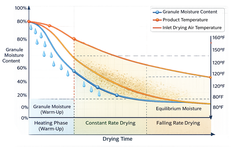
The curves are illustrative. Actual profiles depend on the material, equipment, sensor locations, operating parameters, and endpoint method.
Product temperature may remain below the inlet-air temperature while evaporation is active. As available moisture decreases, product temperature may rise toward the surrounding drying-air or heated-surface temperature.
Temperature convergence can support endpoint assessment but should not automatically be treated as proof that the required residual moisture has been achieved.
Principal dryer types
Fluid-bed dryers
A fluid-bed dryer directs conditioned air upward through a distribution plate and product container. When airflow is sufficient, particles are suspended and mixed within the air stream.
The illustration below shows a representative pharmaceutical fluid-bed dryer with its process-air, product, filtration, and exhaust components.
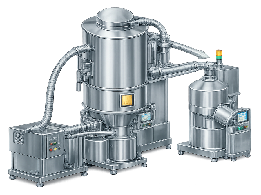
A fluid-bed drying system may include:
- Inlet-air filter stages
- Heating and cooling coils
- Humidity-control components
- Supply fan
- Airflow-control damper or variable-speed drive
- Product bowl or container
- Air-distribution plate
- Expansion chamber
- Product-retention filters
- Filter shaking or blowback
- Exhaust fan and ductwork
- Exhaust filtration
- Solvent-recovery or emission-control equipment
- Temperature, humidity, pressure, and airflow instruments
- Control system and recipe functions
Fluidization improves particle exposure to the drying air but may also cause attrition, fines generation, electrostatic charging, filter loading, or particle entrainment.
Loss of fluidization, airflow channeling, excessive filter differential pressure, or nonuniform loading can create localized differences in heat and mass transfer.
Tray and cabinet dryers
Tray dryers hold material in shallow layers on trays installed within a heated chamber. Air may move by natural circulation or forced circulation, depending on the equipment design.
The illustration below shows a representative pharmaceutical tray dryer with loaded trays and a controlled drying chamber.
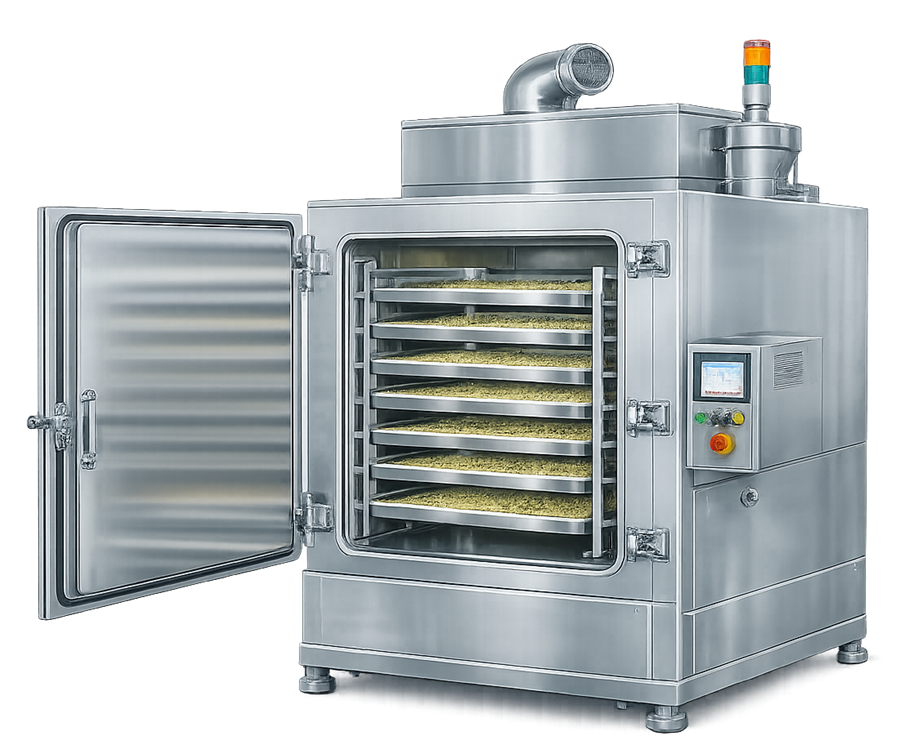
Performance may be influenced by:
- Tray position
- Tray loading
- Material depth
- Material distribution
- Airflow direction
- Fan performance
- Supply and return locations
- Door sealing
- Chamber leakage
- Rack spacing
- Temperature-control sensor location
Tray dryers can provide relatively gentle material handling but may exhibit greater location-dependent variation than a well-fluidized bed. Qualification should therefore evaluate the chamber and approved loading arrangements rather than only the temperature displayed by the controller.
Procedures should define tray identity, rack position, material depth, loading pattern, tray rotation or repositioning where required, and maximum permitted load.
Vacuum dryers
Vacuum dryers reduce system pressure so that evaporation occurs at a lower temperature. Heat may be supplied through shelves, trays, vessel jackets, internal surfaces, or heated agitation.
The illustration below shows a representative pharmaceutical vacuum dryer with a heated chamber, condenser, vacuum system, and controls.
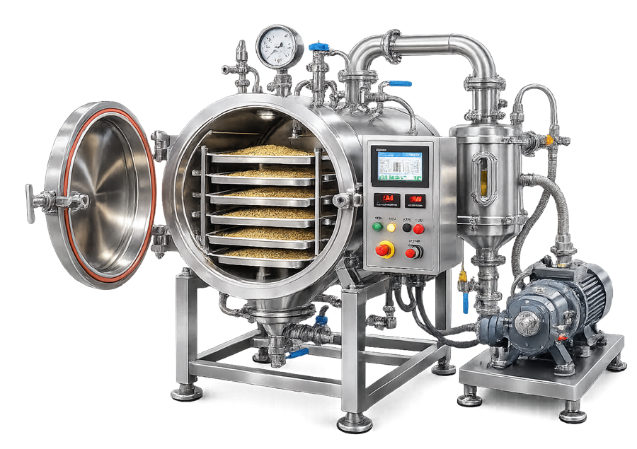
A vacuum drying system may include:
- Sealed chamber or vessel
- Heated shelves, trays, jacket, or agitator
- Vacuum pump
- Condenser
- Receiver
- Pressure-control valve
- Inert-gas connection
- Temperature and pressure instruments
- Solvent-recovery equipment
- Leak-tight product and utility connections
- Automated cycle controls
Critical design considerations include:
- Achievable operating pressure
- Vacuum leak rate
- Heating uniformity
- Condenser capacity
- Vapor-removal capacity
- Product-temperature control
- Prevention of bumping or foaming
- Solvent compatibility
- Discharge and containment
- Safe vacuum break
- Protection against air ingress
For flammable solvents, the system may require inerting, explosion protection, vapor monitoring, controlled exhaust, grounding, bonding, and other safeguards established through the applicable safety assessment.
Integrated and continuous dryers
Some fluid-bed systems combine granulation and drying within one processor. Continuous systems may receive wet material from a continuous granulator and discharge dried material to a mill or blender.
The equipment boundary may include:
- Material feeder
- Granulator interface
- Multiple drying zones
- Air-handling modules
- Discharge or diversion system
- Material tracking
- Startup and shutdown collection
- Residence-time controls
- PAT instruments
- Downstream mill
- Integrated control platform
Qualification should address steady-state operation, transitions, interruptions, material diversion, startup, shutdown, and traceability between incoming and discharged material.
Equipment boundaries and utility interfaces
The dryer boundary should be defined before design review and qualification planning. Depending on the configuration, it may include:
- Product chamber, bowl, trays, racks, or vessel
- Air-handling system
- Supply and exhaust fans
- Ductwork and dampers
- Filters
- Heating and cooling systems
- Steam, hot water, thermal fluid, or electric heaters
- Chilled water
- Compressed air
- Process gas or nitrogen
- Vacuum system
- Condenser and receiver
- Solvent-recovery system
- Product-transfer equipment
- Dust collection
- Instruments and controls
- Safety and environmental controls
- Cleaning system
- Facility and computerized-system interfaces
Utility specifications should reflect intended use. The required quality of compressed air or process gas depends on whether it contacts the product, product-contact surfaces, or only noncritical actuators.
The boundary should also distinguish GMP process controls from occupational, environmental, fire-protection, and equipment-safety functions.
Fluid-bed airflow and material movement
Conditioned inlet air passes through the distribution plate and enters the product bed. The plate and product-container geometry should distribute air without unacceptable channeling or stagnant regions.
The illustration below shows the principal airflow and particle-movement pattern within a fluid-bed dryer.
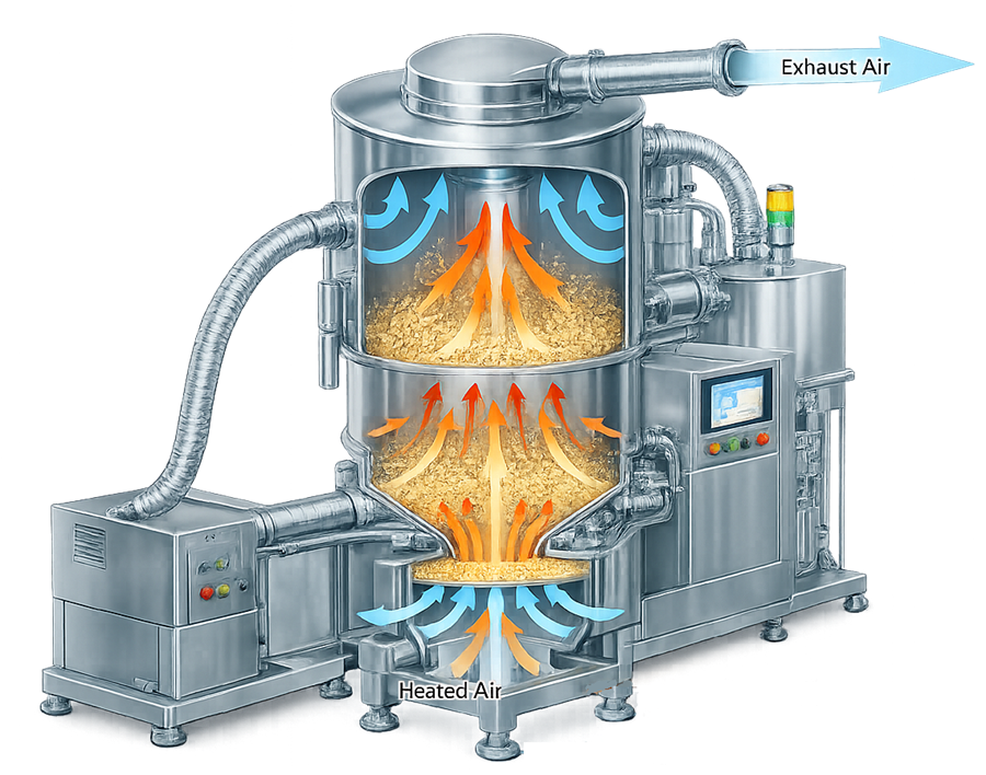
The required airflow must be sufficient to establish and maintain suitable fluidization for the intended load. Excessive airflow may increase attrition, particle entrainment, filter loading, or product loss.
Relevant indicators may include:
- Supply-airflow measurement
- Pressure below the distribution plate
- Product-chamber pressure
- Filter differential pressure
- Fan speed
- Damper position
- Product-bed behavior
- Exhaust-air conditions
A stable airflow indication does not prove uniform fluidization. The relationship among airflow, pressure, product load, filter condition, and material movement should be assessed.
Critical equipment parameters
Temperature
Depending on the dryer, temperature controls may include:
- Inlet-air temperature
- Outlet or exhaust-air temperature
- Product temperature
- Chamber temperature
- Shelf or jacket temperature
- Condenser temperature
- Heating-medium temperature
The controlled and monitored temperatures should be distinguished. An inlet-air sensor may control heater output while product temperature remains a monitored response.
Sensor location, thermal lag, heat loss, and airflow patterns can create differences between displayed temperature and the conditions experienced by the material.
Airflow and air velocity
Airflow affects heat supply, vapor removal, fluidization, and drying rate. The control system may use:
- Volumetric or mass airflow
- Fan speed
- Damper position
- Differential pressure
- Air velocity
- Calculated or inferred airflow
The selected measurement should be suitable for the actual duct arrangement and operating range.
Humidity
Inlet-air humidity affects the moisture-removal capacity of the drying air. Seasonal or weather-related variation may influence a process when the equipment does not actively control or adequately condition humidity.
Relevant measurements may include:
- Relative humidity
- Dew point
- Absolute humidity
- Exhaust humidity
Relative humidity depends on temperature and should not be interpreted independently of the measurement conditions.
Pressure and vacuum
Pressure control may apply to:
- Product-chamber pressure
- Room-to-equipment pressure relationship
- Filter differential pressure
- Distribution-plate differential pressure
- Vacuum-vessel pressure
- Condenser pressure
- Inert-gas pressure
Vacuum instruments should have suitable accuracy and resolution throughout the intended low-pressure range.
Product load and loading configuration
Load can affect:
- Bed depth
- Fluidization
- Airflow resistance
- Heating rate
- Drying time
- Tray temperature distribution
- Vapor load
- Condenser demand
- Discharge performance
The equipment should have a justified minimum and maximum working load. Gross vessel capacity does not define the qualified operating range.
Drying time
Drying time may be a controlled parameter, an endpoint-dependent result, or both. A maximum cycle duration may be established to protect the product, while actual termination may depend on product measurements or a validated endpoint model.
Timer accuracy can be qualified as an equipment function. Product-specific drying time must be established through process development and validation.
Instrumentation and automation
Drying systems may use instruments for:
- Temperature
- Airflow
- Air velocity
- Relative humidity
- Dew point
- Pressure
- Differential pressure
- Vacuum
- Product weight
- Heating-medium flow
- Condenser temperature
- Solvent concentration
- Lower explosive limit
- Product moisture or PAT response
Automated functions may include:
- Recipe management
- Preheating
- Product loading
- Airflow control
- Temperature control
- Humidity conditioning
- Filter shaking
- Vacuum pull-down
- Pressure control
- Heating ramps
- Endpoint determination
- Cooling
- Discharge
- Cleaning
- Alarm handling
- Electronic data recording
Computerized-system controls should address:
- Authorized access
- Approved recipes
- Parameter limits
- Manual-mode restrictions
- Audit trails where applicable
- Data accuracy
- Time synchronization
- Backup and recovery
- Configuration management
- Software changes
- Interfaces with external systems
Automated drying controls may be included within equipment qualification, but full computerized-system validation requires requirements, risk assessment, configuration verification, data-integrity controls, and lifecycle management appropriate to the system’s GMP functions.
Endpoint determination and moisture measurement
Drying endpoint methods may include:
- Fixed time
- Product temperature
- Inlet-to-outlet temperature relationship
- Exhaust humidity
- Weight loss
- Loss on drying
- Karl Fischer water determination
- Near-infrared measurement
- Microwave resonance
- Another qualified PAT method
- A model combining several process signals
Loss on drying measures mass lost under specified test conditions and may include water, residual solvent, or other volatile material. Karl Fischer methods are specifically used to determine water. Results from the two methods should not be treated as interchangeable without supporting evidence.
An endpoint method should define:
- Sampling or measurement location
- Sample handling
- Instrument and analytical method
- Calculation
- Data-processing settings
- Decision rule
- Acceptance criteria
- Response to an invalid or unavailable measurement
- Maximum permitted drying exposure
Equipment qualification verifies that the associated instruments, controls, and sequences function correctly. Product development and process validation establish whether the endpoint predicts the required material condition.
Temperature and airflow mapping
Mapping evaluates spatial and temporal variation within the dryer under defined conditions. It supports identification of locations that may heat, cool, or dry differently.
Mapping may address:
- Empty chamber or unloaded equipment
- Approved product containers, trays, or racks
- Minimum and maximum loads
- Representative loaded conditions
- Airflow distribution
- Temperature distribution
- Heating and cooling transitions
- Recovery after door opening
- Vacuum heating uniformity
- Repeatability between runs
Mapping strategy
A protocol should define:
- Mapping objective
- Equipment configuration
- Load or surrogate
- Sensor quantity
- Sensor locations
- Sensor attachment or restraint
- Data interval
- Reference instruments
- Calibration requirements
- Cycle parameters
- Acceptance criteria
- Data treatment
- Deviation handling
Sensor locations should be selected from equipment geometry, airflow assessment, heating surfaces, supply and return locations, door proximity, tray positions, distribution-plate design, and previous operating data.
Fluid-bed dryer mapping
A fluidized bed is dynamic. Fixed sensors may interfere with material movement or may not represent the temperature history of moving particles.
Mapping may therefore combine:
- Inlet-air measurements
- Exhaust-air measurements
- Product-temperature probes
- Airflow or pressure measurements
- Filter differential pressure
- Samples from defined regions
- PAT data
- Suitable instrumented surrogate studies
The test design should account for the limitations introduced by probe position and material movement.
Tray-dryer mapping
Tray dryers may be mapped across:
- Upper, middle, and lower rack levels
- Front, center, and rear positions
- Locations near supply and return openings
- Door-adjacent locations
- Corners
- Representative tray centers and edges
Loaded mapping should reproduce the approved tray arrangement, material depth, tray spacing, airflow configuration, and load.
Vacuum-dryer mapping
Vacuum-dryer mapping may evaluate:
- Shelf or heated-surface temperatures
- Product-simulating load temperatures
- Chamber pressure
- Heating-medium temperature
- Condenser performance
- Pull-down time
- Leak rate
- Vapor-removal behavior
Mapping should distinguish heating-surface uniformity from actual product-temperature and moisture behavior.
Interpretation of mapping results
Temperature uniformity does not independently demonstrate moisture uniformity. Drying also depends on material depth, particle properties, exposed area, initial moisture, vapor removal, and internal diffusion.
Mapping results should be used to:
- Confirm equipment capability
- Identify location-related differences
- Support sensor placement
- Define loading restrictions
- Select representative or challenging product-sampling locations
- Establish maintenance and requalification controls
Product sampling and residual-moisture distribution
Product-specific drying studies may sample material from locations with different expected heat- and mass-transfer conditions.
The illustration below shows conceptual sampling regions within a fluid-bed product container. The locations must be adapted to the actual equipment, material movement, discharge method, and study objective.
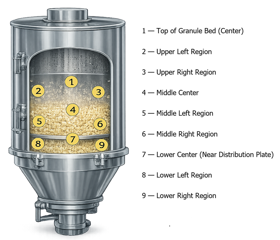
A sampling plan may consider:
- Upper, middle, and lower regions
- Center and peripheral regions
- Locations near the distribution plate
- Areas associated with suspected channeling
- Early, middle, and late discharge fractions
- Samples before and after downstream transfer
Sampling should prevent moisture gain or loss between collection and analysis. Containers, closure time, sample temperature, environmental exposure, and test timing may affect the result.
The associated sampling plan and data collection strategy article addresses representative sampling, sample quantity, location selection, and data interpretation.
Hygienic design and cleaning
Drying equipment should provide access to product-contact and residue-retaining areas, including:
- Product bowls and chambers
- Trays and racks
- Air-distribution plates
- Product filters
- Filter seals
- Expansion chambers
- Spray nozzles where installed
- Sampling ports
- Discharge valves
- Duct transitions
- Vacuum chambers
- Shelves
- Condensers and receivers
- Transfer hoses and connections
Design should address:
- Compatible product-contact materials
- Surface condition
- Drainability
- Cleaning coverage
- Defined disassembly
- Drying after cleaning
- Prevention of cleaning-agent retention
- Inspection access
- Correct component reassembly
- Protection of cleaned equipment
Equipment qualification may verify spray-device operation, wash sequences, flow, pressure, temperature, drainage, and drying. It does not replace the residue limits, recovery studies, sampling, analytical capability, worst-case selection, and reproducibility required by the site’s cleaning validation approach.
Containment and environmental interfaces
Drying may release powder, solvent vapor, heat, humidity, or exhaust contaminants.
Controls may include:
- Closed charging and discharge
- Negative-pressure operation
- Product-retention filters
- Secondary exhaust filters
- Local dust extraction
- Safe-change filter arrangements
- Solvent condensers
- Emission controls
- Inert-gas operation
- Closed sampling
- Wash-in-place systems
The required controls should be based on product hazard, solvent properties, dust explosibility, environmental permits, occupational-exposure objectives, and facility design.
Broader powder controls are addressed in pharmaceutical powder containment and dust collection systems.
User requirements and design qualification
The URS should define measurable requirements for:
- Intended materials and solvents
- Batch-size or throughput range
- Initial and final moisture ranges
- Maximum product temperature
- Required airflow, temperature, humidity, or vacuum ranges
- Loading configurations
- Heating and cooling capability
- Exhaust and vapor handling
- Containment
- Cleaning
- Product-contact materials
- Instrumentation
- Automation and electronic records
- Sampling
- Facility and utility interfaces
- Safety functions
- Maintenance access
- Supplier documentation
Design qualification should verify that the selected equipment and supporting systems satisfy intended use and adequately control identified risks.
Design review should assess the complete dryer, including air handling, vacuum equipment, exhaust, condenser, material transfer, controls, cleaning, and utility interfaces.
Supplier documentation, FAT, and SAT
Supplier documentation may include:
- General arrangement drawings
- Process and instrumentation diagrams
- Airflow diagrams
- Ductwork drawings
- Product-contact drawings
- Materials certificates
- Surface-finish documentation
- Filter specifications
- Fan and heater data
- Vacuum-pump and condenser data
- Instrument lists
- Electrical drawings
- Functional and software specifications
- Alarm and interlock lists
- Cleaning instructions
- Maintenance recommendations
- Operating manuals
Factory acceptance testing may verify:
- Fabrication and components
- Control sequences
- Temperature and airflow control
- Vacuum operation
- Fan and damper operation
- Filter shaking
- Alarms and interlocks
- Recipes
- Data recording
- Safety functions
Site acceptance testing should confirm equipment condition after delivery and operation with installed utilities, ductwork, exhaust, controls, and facility interfaces.
Approved FAT results may support qualification when they remain applicable and traceable. Functions affected by shipment, installation, utilities, configuration, or site integration require site verification.
Installation qualification
Installation qualification should verify, as applicable:
- Equipment identification
- Installed location and orientation
- Product-contact components
- Materials and surface documentation
- Product bowl, trays, racks, shelves, or vessel
- Distribution plate
- Product and exhaust filters
- Fans, heaters, coils, dampers, and ductwork
- Vacuum pump, condenser, and receiver
- Utility connections
- Instruments and calibration status
- Control-system installation
- Software and firmware versions
- Grounding and bonding
- Safety and containment features
- Cleaning connections
- Approved drawings
- Operating and maintenance documentation
Installation discrepancies should be documented and assessed before qualification proceeds.
Operational qualification
Operational qualification should challenge the dryer throughout its approved equipment operating ranges.
Testing may include:
- Minimum and maximum temperature setpoints
- Temperature-control accuracy
- Heating and cooling response
- Airflow or fan-speed range
- Damper operation
- Humidity measurement or control
- Pressure and differential-pressure functions
- Vacuum pull-down and control
- Vacuum leak rate
- Condenser operation
- Filter differential-pressure monitoring
- Filter shaking or blowback
- Timer accuracy
- Recipe limits
- Manual and automatic modes
- Alarm and interlock challenges
- Power-loss and restart response
- Emergency shutdown
- Data recording
- Cleaning sequences
OQ may include empty or defined-load distribution studies when required to demonstrate equipment operation. Product-specific drying time and residual-moisture acceptance criteria should not be assigned as generic equipment OQ criteria.
Equipment-level performance qualification
Equipment-level PQ demonstrates that the installed dryer can perform its intended equipment functions reproducibly under representative operating conditions.
Depending on intended use, testing may evaluate:
- Representative minimum and maximum loads
- Approved tray, rack, bowl, or vessel configurations
- Loaded temperature distribution
- Airflow and pressure behavior
- Fluidization capability
- Vacuum heating performance
- Vapor-removal capability
- Condenser performance
- Charging and discharge
- Material recovery
- Containment
- Repeated recipe execution
- Cleaning functionality
- Extended operation
A suitable surrogate or representative material may be used when its thermal, airflow-resistance, vapor-load, and handling characteristics provide an appropriate challenge.
Equipment-level PQ does not demonstrate that a commercial product consistently meets residual-moisture specifications or performs acceptably during downstream manufacturing. Those conclusions belong to product-specific process validation.
Equipment qualification versus drying-process validation
| Equipment qualification | Product-specific process validation |
|---|---|
| Confirms correct equipment installation and configuration | Confirms the commercial formulation and manufacturing process |
| Verifies temperature, airflow, humidity, pressure, vacuum, timing, alarms, and controls | Establishes product-specific parameter ranges and drying endpoint |
| Evaluates equipment distribution and operating capability | Evaluates residual moisture and product-quality attributes |
| Challenges approved equipment ranges | Challenges formulation, load, and raw-material variability |
| Demonstrates mechanical and control repeatability | Demonstrates batch-to-batch process reproducibility |
| May use suitable surrogate loads | Uses justified product or commercial-process conditions |
| Does not establish commercial drying-cycle acceptance | Supports PPQ and continued process verification |
Product-specific PPQ should evaluate the integrated process under routine commercial conditions and justified challenges. Applicable subjects may include:
- Initial material condition
- Load
- Loading arrangement
- Drying parameters
- Endpoint
- Residual-moisture distribution
- Sampling
- Analytical method
- Hold time
- Transfer
- Milling behavior
- Blend performance
- Compression or encapsulation performance
These activities are addressed further in PPQ strategy and batch definition and general principles of process validation.
Calibration and maintenance
Instruments used to control, record, or make GMP decisions should be included in the applicable calibration program and metrology control.
Relevant devices may include:
- Temperature sensors
- Humidity and dew-point sensors
- Airflow instruments
- Pressure and differential-pressure transmitters
- Vacuum instruments
- Timers
- Load cells
- Heating-medium instruments
- Solvent or lower-explosive-limit detectors
- PAT instruments
- Mapping data loggers
Preventive maintenance should address:
- Fans and motors
- Belts and bearings
- Heaters and coils
- Dampers and actuators
- Filters and filter seals
- Distribution plates
- Product bowls
- Trays and racks
- Door seals
- Vacuum pumps
- Condensers
- Gaskets
- Valves
- Cleaning devices
- Instrument sample lines
Maintenance frequency should reflect equipment criticality, use, supplier recommendations, failure history, and condition. Broader principles are addressed in preventive maintenance and equipment reliability.
Common failure modes and controls
| Failure mode | Potential effect | Typical detection or control |
|---|---|---|
| Heater failure or drift | Slow drying or temperature excursion | Temperature control, alarm, calibration |
| Low airflow | Inadequate drying or loss of fluidization | Airflow, fan, or differential-pressure monitoring |
| Excessive airflow | Attrition, entrainment, or product loss | Airflow limits and filter monitoring |
| Airflow channeling | Localized wet material | Distribution assessment and load control |
| High inlet-air humidity | Reduced moisture-removal capacity | Humidity or dew-point monitoring |
| Product-filter blockage | Reduced airflow and pressure instability | Differential-pressure alarm and filter management |
| Damaged product filter | Product loss or exhaust contamination | Inspection, integrity checks where applicable |
| Vacuum leak | Higher boiling temperature or extended cycle | Leak-rate test and pressure trending |
| Inadequate condenser performance | Poor vapor removal or vacuum control | Condenser-temperature and pressure monitoring |
| Incorrect tray loading | Nonuniform temperature or moisture | Approved loading diagram and line verification |
| Excessive material depth | Extended or nonuniform drying | Load and depth limits |
| Incorrect recipe | Operation outside approved ranges | Access control and recipe approval |
| Endpoint-sensor failure | Premature or delayed termination | Alarm, fallback procedure, independent verification |
| Incomplete cleaning | Carryover or contamination | Cleaning procedure and cleaning validation |
Change control and requalification
Changes should be evaluated for their potential effect on equipment qualification and the validated drying process.
Examples include:
- Heater or fan replacement
- Filter-type change
- Distribution-plate modification
- Ductwork or damper change
- Control-software change
- Recipe modification
- Sensor replacement or relocation
- New tray, rack, bowl, or vessel
- New load range
- Vacuum-pump or condenser change
- Utility modification
- Cleaning-cycle change
- Exhaust or solvent-recovery modification
- Equipment relocation
- New material with different drying characteristics
The impact assessment should determine whether the change requires:
- Document revision
- Calibration or functional testing
- Targeted IQ or OQ
- Distribution remapping
- Equipment-level PQ
- Cleaning assessment
- Product-development studies
- Additional PPQ or process validation
Requalification should focus on affected functions and risks. Periodic review should consider deviations, alarms, calibration, maintenance, filter history, mapping results, cleaning performance, changes, software status, recurring failures, and continued suitability for intended use.
Documentation and traceability
Lifecycle documentation should connect:
- Intended use
- User requirements
- Design specifications
- Risk assessments
- Supplier documentation
- FAT and SAT
- IQ, OQ, and equipment-level PQ
- Mapping protocols and reports
- Instruments and calibration
- Software and configuration
- Operating recipes
- Loading diagrams
- Cleaning procedures
- Maintenance records
- Deviations
- Change controls
- Requalification decisions
- Product-development studies
- PPQ and continued-verification records
The documentation should clearly distinguish evidence of equipment capability from evidence validating a product-specific drying process.
Regulatory basis
21 CFR 211.63 requires manufacturing equipment to be appropriately designed, adequately sized, and suitably located for intended use, cleaning, and maintenance.
21 CFR 211.67 establishes requirements for equipment cleaning, maintenance, written procedures, and records.
21 CFR 211.68 addresses automatic, mechanical, electronic, and computerized equipment, including calibration, inspection, checks, and system controls.
21 CFR 211.110 requires appropriate in-process controls and testing to monitor process output and control manufacturing sources of variability.
FDA’s Process Validation: General Principles and Practices separates facility and equipment qualification from process performance qualification and continued process verification.
Conclusion
Pharmaceutical drying equipment must provide controlled heat transfer, vapor removal, airflow or vacuum, loading, containment, endpoint monitoring, and data capture appropriate to its intended use.
Qualification demonstrates that the installed dryer can operate reproducibly throughout its approved equipment ranges. Mapping characterizes spatial and temporal equipment performance but does not independently prove product-moisture uniformity.
Product-specific development, PPQ, and continued verification must establish the drying parameters, endpoint, residual-moisture distribution, and downstream material performance required for the validated manufacturing process.