Process Gas Systems for GMP Manufacturing
1. Role of Process Gas Systems in GMP Manufacturing
Process gas systems provide gases used to support manufacturing operations, equipment function, and, in some cases, direct interaction with product or product-contact environments. Common process gases in GMP facilities include nitrogen, carbon dioxide, oxygen, and specialty gases supplied via cylinders or bulk sources.
From a regulatory perspective, process gases are considered GMP utilities when their failure or contamination could reasonably impact product quality. This expectation is reflected in 21 CFR 211.42, 211.63, and 211.65, which require facilities and utilities to be suitably designed, controlled, and maintained for their intended use.
Unlike compressed air systems, most process gas systems do not involve extensive on-site conditioning. Risk is therefore driven primarily by supply integrity, distribution design, pressure control, and point-of-use protection.
2. Process Gas Supply Models
Cylinder Supply
Cylinder-supplied gases are commonly used for low to moderate demand applications and specialty gases. Key characteristics include:
- Supplier-controlled gas purity
- On-site risks related to handling, storage, and changeover
- Reliance on procedural and engineering controls
From a GMP standpoint, cylinder systems must prevent misconnection, incorrect gas use, and uncontrolled pressure release. Expectations for segregation, labeling, and connection integrity align with 21 CFR 211.80 and 211.94, as well as general principles outlined in ISO 7396-1 for gas identification and distribution practices, where applicable.
Process gas systems in GMP manufacturing are commonly supplied using cylinder-based systems, bulk storage, or on-site nitrogen generation, depending on demand, purity requirements, and operational risk.
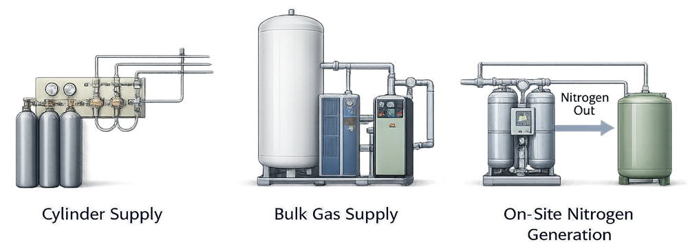
Bulk Gas Supply
Bulk supply systems are typically used for higher-volume gases such as nitrogen or carbon dioxide. These systems introduce additional components, including:
- Central storage tanks
- Vaporizers
- Pressure regulation and safety devices
- Distribution piping
Bulk systems increase mechanical complexity and therefore require more robust design controls to maintain system integrity and prevent contamination or supply interruption. Regulatory expectations for such systems are addressed under general facility and equipment control requirements in 21 CFR 211 Subpart C.
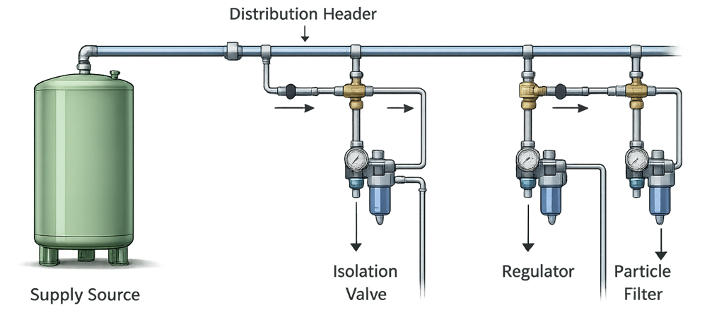
3. Distribution and System Architecture
Regardless of supply model, process gas systems share common architectural elements:
- Supply source
- Pressure regulation and control
- Distribution piping
- Isolation and shutoff valves
- Point-of-use connections
Distribution systems must be designed to:
- Maintain pressure stability
- Prevent cross-connection between different gases
- Use compatible materials of construction
- Allow isolation for maintenance without unintended impact
Clear identification, labeling, and segregation of gas services are consistent with GMP expectations and are reinforced by international standards such as ISO 7396-1 and ISO 14175, where applicable to industrial and process gas systems.
Regardless of how a process gas is supplied, the primary GMP risks are introduced at the distribution and point-of-use level. System design must ensure controlled delivery, effective isolation, and appropriate pressure regulation while preventing cross-connection, backflow, or contamination. The following diagram illustrates a typical process gas distribution arrangement and the key control elements applied at points of use.
4. Intended Use and Risk Considerations
As with other utilities, the design of a process gas system must be driven by intended use and risk to product quality. Process gas applications may include:
- Equipment purging and blanketing
- Environmental control
- Packaging operations
- Direct product contact or exposure to controlled environments
Risk increases as gas proximity to product increases. Where gases contact product or product-contact surfaces, additional controls are expected to prevent contamination and unintended exposure. These expectations align with GMP principles in 21 CFR 211.100 and 211.110, even though specific gas limits are not prescribed.
5. Quality Attributes and Design Expectations
Process gas quality is typically defined by supplier specifications and certificates of analysis. However, facility design must ensure that supplied quality is preserved through distribution and use.
Gas Purity
Purity requirements are driven by intended use and are commonly defined by the supplier. Facility systems must be designed to avoid degradation of purity due to leaks, backflow, or incompatible materials. This expectation aligns with general GMP requirements for material handling and utility control under 21 CFR 211.65.
Particulates and Contaminants
Although process gases are supplied with defined particulate limits, contamination may be introduced through:
- Distribution piping
- Improper connections
- Component wear or degradation
Where risk justifies it, point-of-use filtration may be implemented as an engineering control. International standards such as ISO 8573 may be referenced for particulate classification concepts, recognizing that they are not GMP requirements.
Pressure Control
Pressure regulation must protect both equipment and process integrity. Regulators and safety devices should be selected and installed to maintain stable operation under normal and foreseeable upset conditions, consistent with GMP expectations for controlled operations.
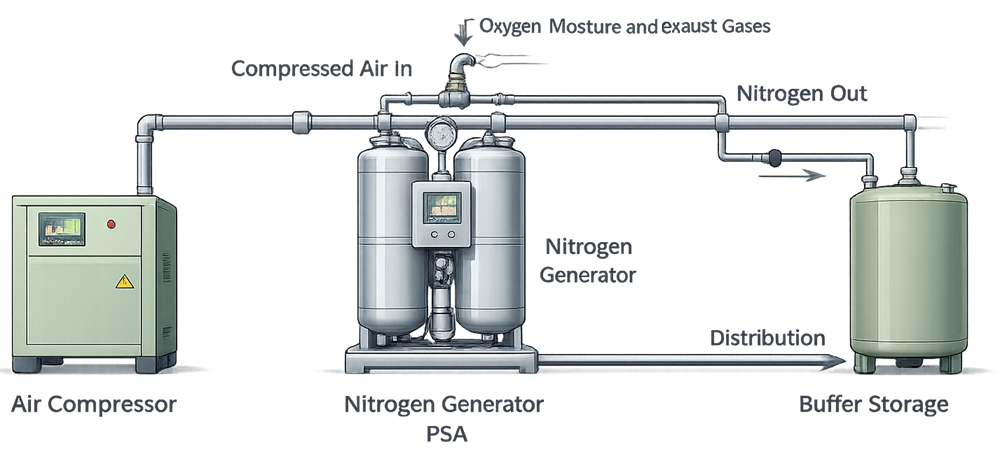
6. Nitrogen Generation Systems as a Special Case
On-site nitrogen generation systems represent a hybrid between traditional process gas supply and compressed air utilities. These systems typically include:
- Compressed air feed
- Pressure Swing Adsorption (PSA) or membrane-based nitrogen generators
- Buffer storage
- Distribution systems
While nitrogen remains a process gas, on-site generation introduces additional failure modes related to feed air quality, generation performance, and system control. As a result, nitrogen generation systems require greater attention to monitoring, alarms, and performance stability.
From a GMP perspective, these systems are still managed as process gas utilities, with design and control expectations derived from intended use rather than generation technology alone.
On-site nitrogen generation systems represent a hybrid between traditional process gas supply and facility utilities, introducing additional complexity related to feed air quality, generation performance, and system control. The following diagram illustrates a typical nitrogen generation arrangement and its key functional elements.
7. Design and Lifecycle Boundary
This article addresses the design expectations for process gas systems used in GMP manufacturing, including cylinder-based supply, bulk systems, and on-site nitrogen generation. Design decisions directly define the scope and depth of qualification, monitoring, and requalification activities, which are addressed separately as part of gas utility lifecycle control.