Temperature Distribution and Qualification Strategy
1. Purpose of Temperature Distribution Studies
Temperature distribution studies demonstrate that thermally controlled equipment maintains required environmental conditions throughout the usable storage or operating volume. These studies confirm that temperature conditions remain within defined limits and that environmental variations do not compromise stored materials, stability studies, or microbiological processes. Thermal qualification applies to a wide range of controlled environments used in pharmaceutical operations, including:
- refrigerators
- freezers
- cold rooms
- walk-in freezers
- incubators
- specialty incubators such as CO₂ or humidity-controlled incubators
- walk-in warm rooms
- stability chambers
The primary objectives of temperature distribution studies are to:
- demonstrate environmental uniformity within the chamber or room
- identify hot and cold locations within the mapped volume
- establish appropriate locations for monitoring sensors
- define the usable qualified storage volume
- verify acceptable recovery following disturbances such as door openings
This article addresses qualification strategy and mapping scope.
2. Regulatory and Technical References
Temperature mapping and qualification practices are commonly derived from industry technical guidance and regulatory expectations, including:
- USP <1079> Good Storage and Shipping Practices
- USP <659> Packaging and Storage Requirements
- ISPE Good Practice Guide: Controlled Temperature Chambers
- PDA Technical Report No. 39 Guidance for Temperature Controlled Storage
- FDA cGMP requirements (21 CFR 211.42, 211.63, 211.68)
These documents establish expectations for environmental control, monitoring, and qualification of temperature-controlled equipment used in pharmaceutical storage and testing environments.
3. Equipment Characteristics Affecting Qualification Strategy
Although the overall qualification approach is similar for temperature-controlled equipment, the design of temperature distribution studies must be adjusted based on the characteristics of the specific system being qualified. Several factors influence the mapping strategy and qualification scope, including:
- equipment size and internal volume
- airflow design and circulation pattern
- temperature operating range
- controlled environmental parameters such as temperature, relative humidity, or CO₂ concentration
- frequency of door openings or chamber access
- sample loading configuration and thermal mass
Small benchtop equipment such as laboratory refrigerators or incubators typically requires evaluation of shelf-to-shelf variability, door-opening recovery, and localized gradients within the chamber. Large storage environments such as cold rooms, walk-in freezers, and warm rooms require evaluation of spatial gradients across the entire room volume, airflow distribution, and potential stratification between floor and ceiling levels. Stability chambers and specialty incubators require additional evaluation of controlled environmental parameters such as relative humidity or CO₂ concentration in addition to temperature performance.
These equipment characteristics determine the appropriate mapping grid density, sensor placement strategy, study duration, and qualification testing conditions used during OQ and PQ.
4. Qualification Lifecycle Strategy
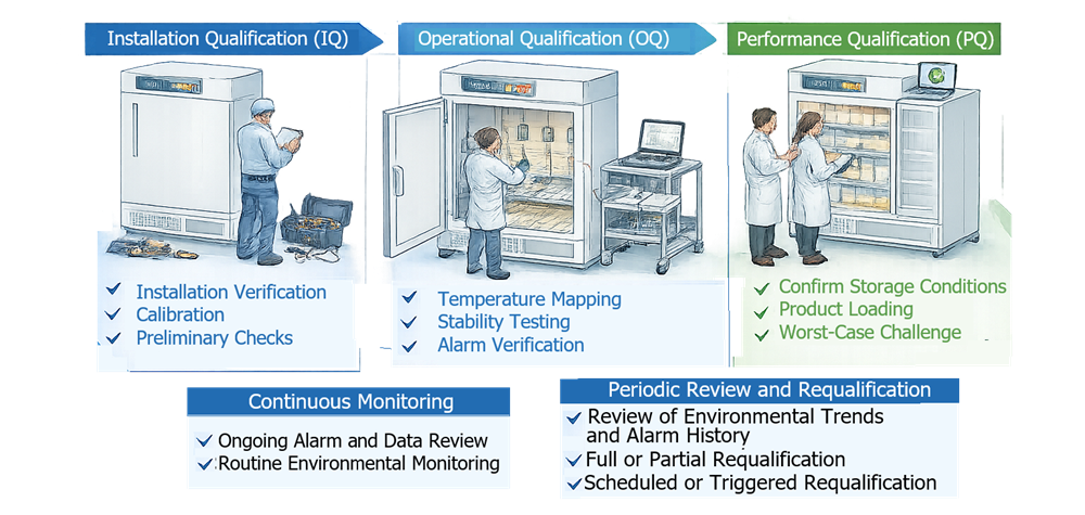
Qualification of temperature-controlled equipment follows the standard lifecycle consisting of Installation Qualification (IQ), Operational Qualification (OQ), and Performance Qualification (PQ). Each phase addresses a different aspect of system suitability.
- Installation Qualification (IQ) verifies that the equipment has been installed according to approved specifications and manufacturer recommendations. This phase confirms correct installation of the chamber, utilities, sensors, alarms, monitoring devices, and control systems.
- Operational Qualification (OQ) demonstrates that the equipment operates correctly across the intended operating range and that environmental conditions remain within defined limits throughout the chamber volume. Temperature distribution studies are typically performed during OQ to identify spatial temperature variation, confirm control accuracy, and establish the qualified storage volume.
- Performance Qualification (PQ) confirms that the equipment performs acceptably under routine operating conditions. PQ testing is conducted using representative loading configurations and typical operational practices such as door openings. Mapping may be repeated or supplemented during PQ to verify that product loading and normal usage do not create unacceptable temperature gradients.
Together, these qualification stages demonstrate that the equipment is properly installed, operates as intended, and maintains the required environmental conditions during routine use.
The diagram below illustrates the lifecycle approach used for qualification and continued control of temperature-controlled equipment. The lifecycle begins with Installation Qualification (IQ), which verifies that the equipment is installed correctly and that required utilities, sensors, and monitoring systems are properly configured. Operational Qualification (OQ) then demonstrates that the environmental control system operates as intended and maintains the required temperature conditions throughout the chamber volume. Performance Qualification (PQ) confirms that the equipment maintains acceptable environmental conditions during routine operation with representative loading and usage conditions.
Following PQ release, the equipment enters routine operation supported by continuous environmental monitoring to ensure that temperature and other controlled parameters remain within defined limits. Environmental monitoring data, alarm history, and operational performance are periodically reviewed as part of ongoing lifecycle management, and periodic review or requalification may be performed when required based on change control, risk assessment, or observed performance trends.
5. Installation Qualification (IQ) Scope
IQ confirms that the equipment has been installed correctly and is ready for operational testing. Typical IQ verification includes:
- equipment identification (manufacturer, model, serial number)
- installation location and environmental suitability
- utility connections
- shelving and internal configuration
- installed control sensors and monitoring sensors
- alarm configuration
- control system settings
- documentation availability
- calibration status of installed sensors
For cold rooms, walk-in freezers, and walk-in warm rooms, IQ should also include verification of the room construction and environmental control infrastructure. Typical installation verification may include:
- insulated panel construction and panel sealing
- floor and ceiling insulation integrity
- door construction, door seals, and door safety release mechanisms
- lighting fixtures and electrical installations suitable for the temperature environment
- evaporator or air-handling units and associated circulation fans
- refrigeration piping and condensate drain routing
- location of supply and return air vents
- temperature control sensors and monitoring sensors
- alarm annunciation devices and remote monitoring connections
These checks confirm that the controlled room environment has been installed correctly and that all structural and mechanical components required for temperature control are present and properly configured.
6. Operational Qualification (OQ)
6.1 OQ Objectives
OQ demonstrates that the equipment operates within the defined temperature range and that environmental conditions remain stable across the chamber or room volume. Typical OQ testing applicable to most temperature-controlled equipment includes to confirm that the environmental control system performs correctly under normal operating conditions:
- temperature mapping of the chamber or storage area
- verification of temperature setpoint accuracy
- alarm challenge testing
- door opening recovery testing
- power interruption and restart behavior
- verification of control and monitoring sensors
For stability chambers and humidity-controlled systems, OQ should also verify:
- relative humidity control accuracy
- humidity distribution across the chamber
- humidity recovery following door openings
For specialty incubators, OQ may include verification of additional controlled parameters such as:
- CO₂ concentration control and stability
- humidity control where applicable
- recovery of controlled parameters after chamber access
For cold rooms, walk-in freezers, and walk-in warm rooms, OQ should place additional emphasis on:
- temperature distribution across large room volumes
- airflow distribution and potential stratification
- performance under representative ambient room conditions
Separating general and equipment-specific tests helps ensure that the qualification strategy is appropriately tailored to the type of thermal equipment being evaluated.
6.2 OQ Mapping Conditions
Temperature mapping should be performed under controlled and documented conditions. Mapping conditions typically include:
- empty chamber mapping
- controlled ambient conditions
- closed-door steady-state operation
- defined door-opening disturbance testing
Run duration should be sufficient to demonstrate temperature stability. For most equipment types, mapping studies are typically conducted for at least 24 hours to capture multiple compressor cycles and environmental fluctuations.
6.3 Sensor Quantity and Mapping Grid
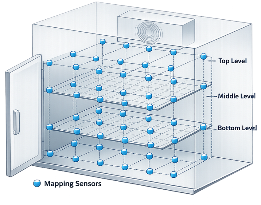
The number of sensors required for mapping depends on chamber volume and geometry. Sensors should be distributed in a three-dimensional grid covering the entire usable volume. Typical sensor quantity guidance is shown below.
| Chamber Volume | Minimum Mapping Sensors |
|---|---|
| < 0.5 m³ (small incubator / refrigerator) | 9 sensors |
| 0.5 – 2 m³ | 12 sensors |
| 2 – 10 m³ | 15–20 sensors |
| 10 – 30 m³ | 20–30 sensors |
| > 30 m³ (large cold room) | 30–50 sensors |
Additional sensors should be placed in potential worst-case areas such as:
- near doors
- near supply vents
- near return air ducts
- top and bottom shelf levels
- corners of the chamber
Mapping grids should represent the usable storage volume, not only the geometric center of the chamber. The diagram below illustrates a typical three-dimensional mapping grid used during temperature distribution studies. Sensors are placed across the chamber volume to evaluate spatial temperature variation and identify potential hot and cold locations. Mapping positions typically include upper, middle, and lower shelf levels as well as corner locations within the chamber.
7. Performance Qualification (PQ)
PQ demonstrates that the chamber performs acceptably under routine operating conditions. PQ differs from OQ because testing is conducted under representative loading and usage conditions.
7.1 Load Conditions
PQ should include representative loading conditions. Typical load conditions include:
- representative product load
- simulated product load (water bottles or thermal mass blocks)
- typical shelf configuration used in operation
The objective is to demonstrate that normal loading does not adversely affect temperature distribution or environmental stability.
7.2 Sensor Quantity During PQ Studies
The number of sensors used during Performance Qualification is typically lower than the quantity used during Operational Qualification mapping. OQ mapping establishes the temperature distribution across the entire chamber volume and identifies the locations representing worst-case environmental conditions.
During PQ studies, sensors are normally placed at these previously identified worst-case locations rather than across the full mapping grid. The objective is to confirm that environmental conditions remain within defined limits under representative operating conditions and loading configurations. Therefore, PQ monitoring typically includes:
- monitoring at the identified warmest location
- monitoring at the identified coldest location
- monitoring at representative product locations where applicable
- verification of the installed monitoring sensor location
Additional sensors may be used when evaluating new loading configurations, operational conditions, or equipment modifications that could affect temperature distribution.
This approach ensures that PQ confirms environmental performance under routine use conditions while relying on the comprehensive spatial characterization previously established during OQ mapping.
7.3 Number of PQ Runs
Multiple PQ runs are normally required to demonstrate consistent performance. Typical practice includes minimum three independent PQ runs to provide evidence of repeatability and support statistical confidence in chamber performance.
Each run should demonstrate:
- temperature within defined limits
- acceptable recovery following disturbances
- consistent environmental control
Three runs provide evidence of repeatability and support statistical confidence in chamber performance.
7.4 PQ Run Duration
PQ runs should reflect realistic operating conditions. Typical run duration shall be 24 to 72 hours depending on equipment type. Longer studies may be required for:
- large cold rooms
- stability chambers
- equipment with long recovery times
Run duration should capture:
- multiple compressor cycles
- temperature stabilization periods
- representative operational disturbances
8. Acceptance Criteria
Acceptance criteria should be defined separately for each qualification stage.
8.1 IQ Acceptance Criteria
IQ acceptance criteria typically include:
- equipment installed according to approved specifications
- utilities connected correctly
- monitoring sensors installed and calibrated
- alarm configuration verified
- documentation complete
8.2 OQ Acceptance Criteria
OQ acceptance criteria typically include:
- all mapped locations within the defined operating temperature range
- acceptable temperature variation across the mapped volume
- stable temperature control over time
- correct alarm activation at predefined limits
- acceptable recovery following door opening or other disturbances
During OQ temperature mapping, sensors are distributed throughout the entire chamber or room volume to evaluate environmental conditions across all locations. Mapping results are used to determine whether the equipment can maintain the required environmental conditions throughout the usable storage or operating space.
If mapping demonstrates that certain peripheral areas of the chamber experience transient temperature disturbances or localized gradients, these areas may be excluded from the usable storage region. Examples may include areas near doors, air supply discharge points, evaporators, or chamber walls where airflow patterns may cause temporary environmental variation.
Based on the mapping results, the usable chamber volume may be defined as the portion of the chamber where temperature conditions consistently remain within the defined acceptance criteria. Materials or samples should only be stored within this qualified storage region.
For stability chambers, acceptance criteria must also confirm that relative humidity remains within the defined humidity range and that humidity conditions are stable across the mapped chamber volume.
For specialty incubators, acceptance criteria should include verification of additional controlled parameters where applicable. These may include:
- CO₂ concentration maintained within the defined operating range
- humidity maintained within the defined range for humidity-controlled incubators
- stable recovery of controlled parameters following chamber access events
These criteria confirm that all controlled environmental parameters remain within the required limits across the defined usable chamber volume.
8.3 PQ Acceptance Criteria
PQ acceptance criteria confirm acceptable performance under routine use. Typical PQ acceptance criteria include:
- temperature maintained within limits under representative loading
- no unacceptable gradients across storage locations
- acceptable recovery after door openings
- consistent performance across multiple runs
PQ acceptance demonstrates that the equipment is suitable for its intended operational use.
9. Selection of Monitoring Sensor Locations
A key output of temperature mapping is identification of permanent monitoring sensor locations. Sensors should be placed at locations representing worst-case environmental conditions identified during mapping studies. These locations often include:
- warmest locations within the chamber
- coldest locations within the chamber
- areas near doors or airflow disturbances
Permanent monitoring sensors should represent conditions experienced by stored materials.
10. Requalification and Remapping
Remapping or requalification should be performed when events occur that could affect temperature distribution or environmental control performance of the equipment or storage area. Typical triggers include:
- equipment relocation
- major repairs or maintenance activities
- replacement of refrigeration or environmental control components
- significant changes in shelving or loading configuration
- modification of operating setpoints
- recurring temperature excursions or abnormal environmental trends
All such changes should be evaluated through the site change control system. A documented risk assessment should be performed to determine the potential impact of the change on temperature distribution, monitoring strategy, and qualified storage volume. Based on this assessment, the scope of requalification should be defined, which may include partial testing, targeted mapping, or full requalification.
In addition to event-driven requalification, temperature-controlled equipment should be subject to periodic assessment to confirm continued performance over time. Periodic evaluation may include review of environmental monitoring data, alarm history, maintenance records, and operational performance trends. Where these assessments indicate potential degradation of performance, additional qualification activities or remapping studies may be required.
This approach ensures that the qualified state of temperature-controlled equipment is maintained throughout its operational lifecycle.