

Thermal Mapping Sensors, Data Loggers, and Uncertainty
Thermal mapping conclusions are only as reliable as the measurement system that produced the data. Sensor technology, logger electronics, calibration, response time, sampling interval, time synchronization, placement, software, and data handling can each affect the recorded result.
A calibrated logger does not automatically make a study valid. The instrument must be suitable for the expected range, capable of detecting relevant changes, correctly configured, placed in the approved location, synchronized with the other loggers, and supported by reliable electronic records.
This article addresses instrumentation selection, calibration, measurement uncertainty, deployment, data retrieval, software, and failed-instrument assessment. Study configurations, sensor quantity, and placement strategy are addressed in Thermal Mapping Study Design and Qualification Strategy. Permanent probes, alarms, and continuous monitoring are addressed in Temperature Monitoring, Alarm Systems, and Data Integrity.
Thermal-Mapping Measurement System
A thermal-mapping measurement system may include:
- Temperature sensors
- Relative-humidity sensors
- CO₂ sensors where applicable
- Standalone data loggers
- Wireless data loggers
- Wired data-acquisition units
- Transmitters
- Communication gateways
- Batteries or power supplies
- Configuration software
- Data-download software
- Analysis software
- Computers or servers
- Calibration equipment
- Reference standards
- Electronic records
The complete measurement path should be understood:
Environmental condition → Sensor → Logger electronics → Stored value → Data transfer → Software → Reported result
A deficiency at any point can affect the qualification conclusion.
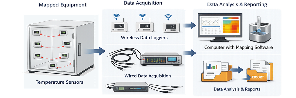
The measurement-system boundary should distinguish temporary mapping instrumentation from the equipment controller and permanent monitoring system.
Instrumentation Requirements
Instrumentation requirements should be defined before equipment selection or protocol execution. Requirements may include:
- Measurement parameter
- Intended temperature or humidity range
- Required accuracy
- Resolution
- Response time
- Sampling interval
- Memory capacity
- Battery duration
- Channel quantity
- Sensor dimensions
- Probe construction
- Cable length
- Wireless communication
- Environmental protection
- Cryogenic suitability
- Calibration range
- Calibration uncertainty
- Time synchronization
- Data-security controls
- Software functions
- Export format
- Record retention
- Audit-trail requirements
- User-access controls
- Backup and recovery
Instrument specifications should be appropriate for the study acceptance criteria. A logger whose uncertainty is large relative to the permitted temperature range may not support an unambiguous qualification decision.
Temperature-Sensor Technologies
Several sensor technologies are used for pharmaceutical thermal mapping. No single technology is best for every application.
Thermistors
Thermistors change electrical resistance as temperature changes.
Advantages include:
- High sensitivity over limited ranges
- Small sensor size
- Good response time
- Common availability in compact data loggers
- Suitability for refrigerated and controlled-room-temperature studies
Limitations may include:
- Nonlinear response
- Restricted operating range
- Drift after thermal or mechanical stress
- Dependence on logger-specific conversion equations
Thermistors are commonly used in self-contained mapping loggers.
Resistance Temperature Detectors
Resistance temperature detectors, or RTDs, use the predictable resistance change of a metal element, commonly platinum.
Advantages include:
- Good stability
- Broad useful range
- High measurement accuracy
- Strong suitability for reference and comparison measurements
Limitations may include:
- Lead-wire effects
- Sensor self-heating
- Larger probe construction
- Slower response in some assemblies
- Higher cost
Platinum RTDs such as Pt100 and Pt1000 devices are common in reference instruments, installed monitoring systems, and calibration equipment.
Thermocouples
Thermocouples generate a voltage related to the temperature difference between the measuring junction and reference junction. Advantages include:
- Wide measurement range
- Small junction size
- Fast response
- Flexible probe construction
- Suitability for multi-channel wired systems
Limitations may include:
- Lower accuracy than some RTDs or thermistors
- Electrical noise
- Wire inhomogeneity
- Connector errors
- Cold-junction compensation
- Cable-routing effects
- Mechanical damage to small junctions
Thermocouples are useful for large-channel-count studies and applications extending beyond normal pharmaceutical storage ranges. Their use should be based on functional requirements, not an assumption that wired thermocouples are required for every large room.
Semiconductor and Digital Sensors
Some compact data loggers use integrated semiconductor sensors with digital output. Advantages may include:
- Compact construction
- Direct digital communication
- Reduced analog signal-conditioning requirements
- Factory characterization
- Low power consumption
Limitations may include:
- Restricted temperature range
- Limited field adjustability
- Dependence on embedded firmware
- Replacement of the complete logger when the sensor fails
The complete logger should be calibrated as the measurement system used in the study.
Relative-Humidity Sensors
Capacitive relative-humidity sensors are commonly used in stability chambers and humidity-controlled storage areas. Selection should consider:
- Humidity range
- Temperature range
- Accuracy
- Hysteresis
- Response time
- Long-term drift
- Condensation exposure
- Chemical contamination
- Sensor recovery
- Calibration capability
Relative-humidity measurement depends on temperature. A humidity probe and its associated temperature measurement should therefore be evaluated as an integrated instrument.
Humidity sensors can drift after prolonged high-humidity exposure or condensation. Calibration and study-impact assessments should reflect these limitations.
Cryogenic Sensors
Cryogenic applications require sensors, cables, insulation, and calibration methods suitable for extremely low temperatures. Potential technologies include:
- Platinum RTDs
- Cryogenic thermistors
- Thermocouples
- Specialized semiconductor sensors
The assessment should address:
- Operating range
- Calibration capability
- Thermal contact
- Immersion depth
- Lead-wire effects
- Self-heating
- Response time
- Cable flexibility
- Mechanical damage
- Condensation and icing
- Performance during repeated thermal cycling
A sensor calibrated only near room temperature may be unsuitable for qualification at cryogenic conditions.
Cryogenic vessel mapping is addressed in Liquid Nitrogen Cryogenic Storage: Design and Qualification.
Accuracy, Resolution, Precision, and Uncertainty
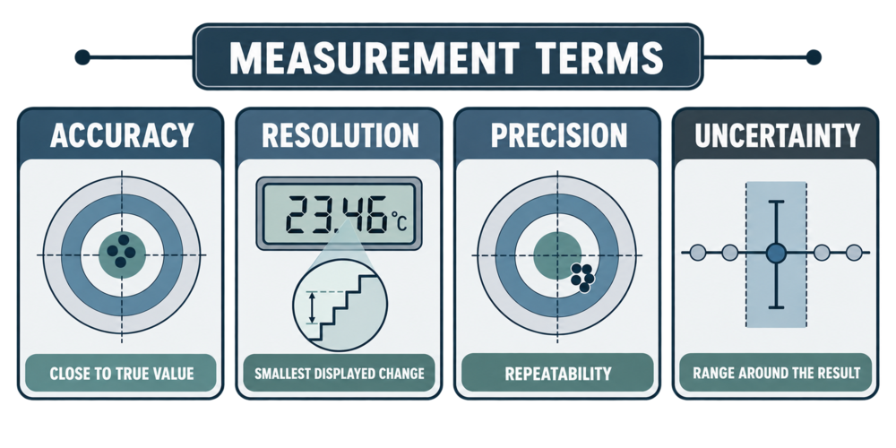
These terms describe different measurement characteristics and should not be used interchangeably.
Accuracy
Accuracy describes how close a measurement is to the accepted reference value. Manufacturers often express accuracy as a maximum permitted error over a stated range. An accuracy specification may depend on:
- Temperature range
- Sensor type
- Logger electronics
- Calibration adjustment
- Environmental conditions
- Time since calibration
Resolution
Resolution is the smallest change displayed or stored by the instrument. A logger displaying 0.01°C does not necessarily measure temperature with ±0.01°C accuracy. Additional displayed digits do not prove measurement quality.
Precision
Precision describes the closeness of repeated measurements under defined conditions. A sensor may produce highly repeatable readings that are consistently offset from the reference value.
Precision without adequate accuracy can produce consistent but incorrect results.
Measurement Uncertainty
Measurement uncertainty describes the range around a result within which the value being measured is reasonably expected to lie.
Uncertainty is not proof that the measurement is wrong. It expresses the remaining doubt after the measurement system and calibration process have been evaluated.
Selection of Accuracy
Required accuracy should be based on:
- Approved operating range
- Study acceptance criteria
- Expected temperature variation
- Material or process risk
- Required decision confidence
- Calibration capability
- Measurement uncertainty
Fixed expectations such as ±0.5°C for every refrigerator or ±1°C for every freezer should not be presented as universal requirements.
For a narrow acceptance range, instrumentation should normally have substantially better measurement capability than the total permitted range. The selected relationship should be defined through the site’s calibration, qualification, or decision-rule procedure.
The manufacturer’s accuracy specification should be evaluated across the complete study range, not only at room temperature.
Data-Logger Architectures
Thermal mapping may use standalone, wireless, wired, or combined systems.
Standalone Data Loggers
Standalone loggers store measurements in internal memory for download after the study. Advantages include:
- Simple deployment
- No cabling
- Minimal effect on door closure
- Operation without network availability
- Flexible placement
Limitations include:
- No real-time visibility
- Data unavailable until retrieval
- Battery dependence
- Memory limitations
- Delayed detection of logger failure
- Manual time-synchronization requirements
A standalone logger may also have wireless download capability. Standalone and wireless are not mutually exclusive categories.
Wireless Data Loggers
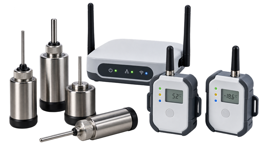
Wireless systems transmit data during the study or provide wireless configuration and download. Wireless temperature data loggers combine a sensor, measurement electronics, memory, battery, and communication functions within compact individual devices. Their physical design supports flexible placement throughout chambers, rooms, racks, and storage areas.
Advantages may include:
- Real-time or near-real-time review
- Reduced cabling
- Early identification of failed sensors
- Flexible deployment
- Remote study supervision
Limitations may include:
- Signal attenuation
- Communication gaps
- Metal-enclosure interference
- Network dependency
- Cybersecurity requirements
- Gateway configuration
- Battery consumption
Wireless communication loss should not automatically cause data loss. Where required, the logger should buffer readings locally and transmit them after communication is restored.
Wired Data-Acquisition Systems
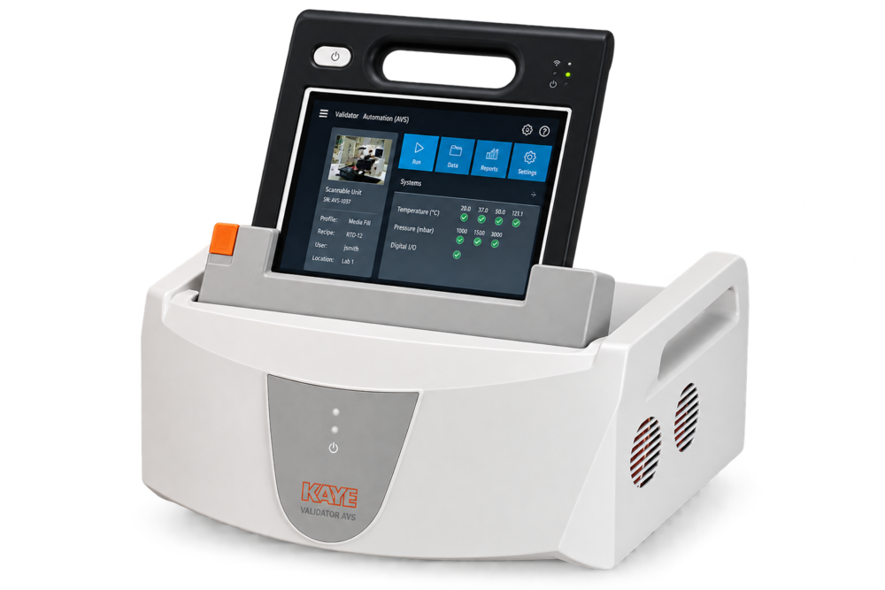
Wired systems connect multiple sensors to a central acquisition unit. Calibration and drift control extend from use-range calibration through deployment, study execution, post-study assessment, and data-impact evaluation.
Advantages may include:
- High channel count
- Centralized configuration
- Real-time display
- Rapid sampling
- Common time base
- Direct observation during challenge tests
Limitations may include:
- Cable routing
- Door-seal interference
- Heat transfer along cables
- Electrical noise
- Channel-identification errors
- Sensor disconnection
- Installation complexity
Cables passing through doors or seals can alter the system being mapped. Approved access ports should be used where possible.
Selecting Wired or Wireless Instrumentation
Selection should be based on study function rather than equipment size alone.
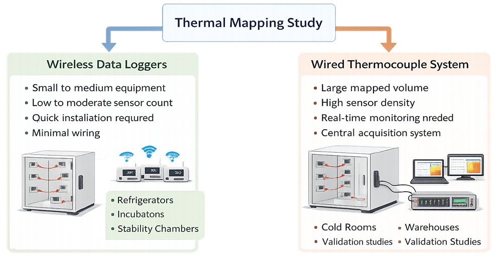
Relevant considerations include:
- Number of channels
- Required sampling speed
- Need for real-time review
- Access-port availability
- Door-seal integrity
- Radio-frequency transmission
- Metal enclosure
- Battery duration
- Memory capacity
- Data-buffering capability
- Installation time
- Study duration
- Environmental range
- Software controls
- Calibration method
A large warehouse can be mapped effectively with wireless or standalone loggers. A small chamber may require a wired system when very fast sampling or specialized probes are needed.
Measurement Range
The specified instrument range should cover:
- Normal operating temperatures
- Expected warm and cold locations
- Door-opening conditions
- Power-loss conditions
- Defrost conditions
- Seasonal extremes
- Calibration points
- Failure challenges
An instrument should not be operated outside its specified range unless the resulting data are treated as invalid or another approved assessment applies.
Accuracy and uncertainty may vary across the range. Calibration points should represent the critical use range rather than relying on one point near ambient temperature.
Sensor Response Time
Response time is the time required for a sensor to respond to a temperature change under defined conditions. Response depends on:
- Sensor technology
- Probe mass
- Protective sheath
- Air velocity
- Immersion
- Mounting
- Contact with surfaces
- Buffering material
- Magnitude of temperature change
Air-temperature mapping generally requires sensors capable of following relevant environmental changes. Excessively slow sensors can smooth short excursions and make recovery appear slower or less severe than it actually was.
A fast sensor may show brief air-temperature fluctuations that a product or buffered probe would not follow. The measurement objective should determine the required response.
Manufacturer response-time specifications should be interpreted carefully because test conditions may differ from the qualification application.
Buffered and Unbuffered Sensors
An unbuffered sensor responds directly to surrounding air and is generally appropriate for mapping air-temperature distribution.
A buffered sensor is placed in material such as glycol, glass beads, sand, or a product-simulating medium. Buffering slows the response and may better represent product-temperature behavior.
Buffered probes may be useful for:
- Routine monitoring
- Alarm control
- Product-simulating studies
- Power-loss evaluation
- Door-opening exposure assessment
Buffered probes should not replace unbuffered sensors when the study objective is to identify air-temperature gradients or short spatial disturbances.
The buffer material, quantity, container, probe position, and response characteristics should be defined.
Sampling Interval
The sampling interval determines how frequently the logger records a measurement. Selection should consider:
- Expected rate of temperature change
- Control cycles
- Defrost cycles
- Door-opening duration
- Recovery time
- Sensor response
- Study duration
- Memory capacity
- Battery duration
- Data volume
- Time synchronization
There is no universal five-minute, fifteen-minute, or one-minute requirement.
A long interval can miss short events or distort recovery-time calculations. A very short interval can create large data sets without adding meaningful information.
The interval should be justified in the protocol and verified in the downloaded data.
Time Synchronization
Sensor data must be aligned accurately when the study compares multiple locations or evaluates short challenges. Synchronization controls should address:
- Computer or server time
- Logger clock
- Time zone
- Daylight-saving changes
- Clock drift
- Manual start
- Delayed start
- Wireless synchronization
- Acquisition-system channel timing
All loggers should be synchronized before deployment according to the approved procedure.
For long studies or devices with known clock drift, post-study time comparison may be required. Time corrections should be documented and should not alter the original records.
Memory and Battery Capacity
Logger memory and battery capacity should exceed the planned study requirement with an appropriate margin. The assessment should consider:
- Number of channels
- Sampling interval
- Study duration
- Wireless transmission
- Environmental temperature
- Battery chemistry
- Battery age
- Display use
- Data-buffering requirements
Battery performance can decline substantially at low temperatures. A logger suitable at room temperature may fail prematurely in a freezer or cryogenic application.
Battery replacement should be controlled. If replacement opens the instrument enclosure or affects calibration, the impact should be assessed.
Calibration
Calibration compares an instrument’s indication with a reference standard under defined conditions. Calibration does not automatically adjust the instrument. A calibration can document the observed error without changing the device.
Calibration records should identify:
- Instrument
- Sensor
- Logger or readout
- Calibration date
- Calibration method
- Reference standard
- Traceability
- Calibration points
- As-found results
- Adjustment where performed
- As-left results
- Acceptance criteria
- Measurement uncertainty
- Environmental conditions
- Calibration laboratory
- Next due date where applicable
The sensor and logger electronics should be calibrated as the system used for the study unless separate calibration and technical justification establish equivalent control.
Calibration Range and Points
Calibration points should represent the intended use range and critical study decisions. Potential point selection may include:
- Lower acceptance region
- Normal operating region
- Upper acceptance region
- Alarm or action levels
- Expected challenge temperatures
Three-point calibration is common for a defined operating range, but the required number of points should be justified.
A calibration performed at 0°C, 25°C, and 50°C may not adequately support use at −80°C. Similarly, a room-temperature calibration does not demonstrate cryogenic performance.
Interpolation between calibration points may be reasonable. Extrapolation beyond the calibrated range requires specific justification.
Calibration Intervals
Calibration intervals should be established using risk and instrument performance. Factors include:
- Manufacturer information
- Sensor technology
- Historical drift
- Frequency of use
- Mechanical handling
- Thermal cycling
- Use at extreme temperatures
- Storage conditions
- Previous calibration failures
- Criticality
- Required accuracy
Annual calibration may be a practical administrative interval, but it is not a universal requirement.
Intervals may be shortened when drift or failures increase. They may be extended when supported by stable historical performance and the approved calibration program.
Pre-Study Verification
Before deployment, each logger should be checked for:
- Correct identity
- Current calibration
- Physical condition
- Battery status
- Memory capacity
- Correct measurement range
- Correct sampling interval
- Correct start mode
- Time synchronization
- Communication
- Channel assignment
- Sensor connection
- Previous data clearance
- Configuration lock where applicable
A short comparison at a stable condition can identify gross offsets or configuration errors. This functional check does not replace calibration.
Post-Study Calibration and Drift Assessment
Post-study calibration or verification can determine whether logger performance changed during deployment.
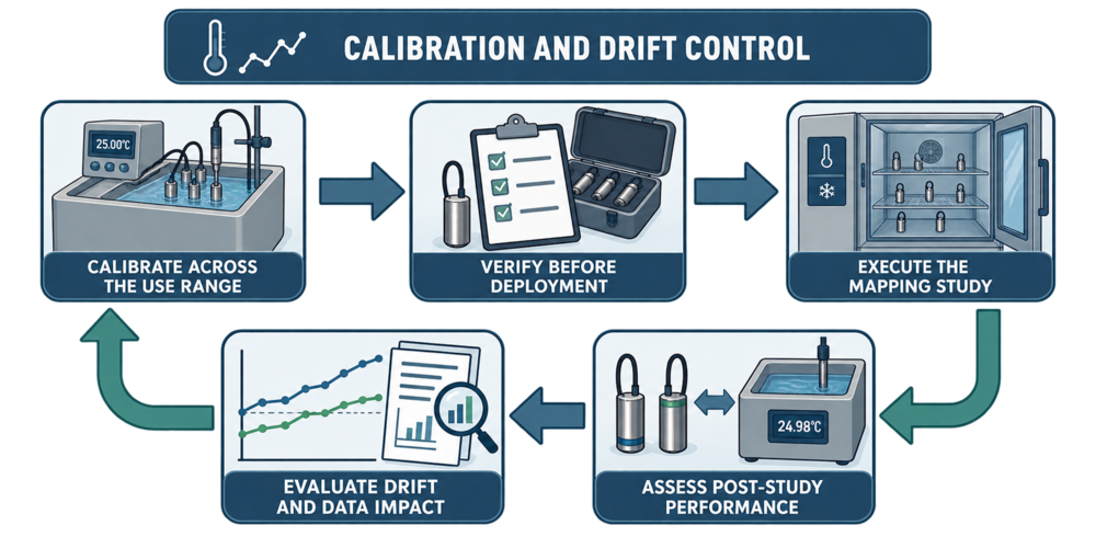
Post-study checks may be appropriate when:
- Required by procedure
- Sensors were exposed to extreme temperatures
- Sensors experienced mechanical stress
- The study was unusually long
- A logger produced suspect data
- Results were close to an acceptance limit
- Historical drift is significant
- Study risk justifies direct confirmation
Post-study calibration should be risk-based and procedure-driven. It is not automatically mandatory for every study.
As-Found and As-Left Results
As-found data document instrument performance before adjustment.
As-left data document performance after adjustment or repair.
As-found results are essential for evaluating whether data generated since the previous acceptable calibration may have been affected.
A calibration certificate reporting only passing as-left results can conceal the condition in which the instrument was received.
When adjustment is performed, the calibration record should preserve both result sets.
Drift
Drift is the change in instrument indication over time. Drift may result from:
- Sensor aging
- Thermal cycling
- Mechanical shock
- Moisture
- Condensation
- Cable damage
- Battery condition
- Electronic component changes
- Contamination
- Calibration adjustment
Drift should be evaluated for magnitude, direction, and effect on study conclusions.
A positive drift may make recorded temperatures appear higher than the actual temperature. A negative drift may make them appear lower.
The direction of drift is important when assessing results near a high or low acceptance limit.
Calibration Failure and Study Impact
A failed calibration does not automatically invalidate every result generated by the instrument. It requires a documented impact assessment. The assessment should consider:
- Magnitude of error
- Direction of error
- Calibration points affected
- Study range
- Acceptance margin
- Sensor location
- Duration of use
- Nearby logger results
- Redundant measurements
- Observed trend consistency
- Study objective
- Potential effect on pass/fail decisions
Possible conclusions include:
- No effect on the study conclusion
- Correctable result using an approved method
- Localized data invalidity
- Need for supplemental testing
- Need to repeat part of the study
- Complete study invalidation
Correction should not be applied retrospectively unless the relationship is scientifically justified, controlled, and traceable.
Measurement Traceability
Measurement traceability is the documented chain connecting a measurement result to a recognized reference through calibrated standards.
Traceability requires more than the statement “NIST traceable.” The calibration record should identify the reference standards and the unbroken calibration relationship supporting the result.
NIST provides calibration services and technical information for industrial thermometers through its Industrial Thermometer Calibrations program.
Traceability does not eliminate measurement uncertainty. Each comparison in the calibration chain contributes uncertainty.
Measurement-Uncertainty Contributors
Potential uncertainty contributors include:
- Reference-standard calibration
- Calibration bath stability
- Calibration bath uniformity
- Sensor resolution
- Logger electronics
- Repeatability
- Sensor drift
- Reference-probe placement
- Device-under-test placement
- Immersion depth
- Lead-wire effects
- Self-heating
- Environmental conditions
- Data rounding
- Calibration method
Only contributors relevant to the measurement system and method should be included.
Uncertainty from sensor placement within the mapped equipment is generally a study-design issue rather than part of the instrument calibration uncertainty. It should still be considered when interpreting the complete qualification result.
Calculating Combined Uncertainty
When uncertainty contributors are independent and expressed as standard uncertainties, they are commonly combined using the root-sum-square method:
Combined standard uncertainty = √(u₁² + u₂² + u₃² + … + uₙ²) , where:
- u₁ through uₙ are the individual standard-uncertainty contributors
- √ means square root
Expanded uncertainty is calculated as:
Expanded uncertainty (U) = Coverage factor (k) × Combined standard uncertainty
A coverage factor near 2 is commonly used to represent approximately 95 percent coverage when the statistical assumptions are appropriate.
NIST Technical Note 1297 describes the evaluation and expression of measurement uncertainty. The site calculation should follow its approved metrology or calibration procedure.
Applying Uncertainty Near a Limit
Consider a logger reading of 8.0°C with an expanded uncertainty of ±0.3°C.
The measurement result is expressed as: 8.0°C ± 0.3°C
The possible value represented by the result extends from approximately 7.7°C to 8.3°C. If the applicable upper limit is 8.0°C, the reading does not provide an unambiguous passing decision.
The approved decision rule should define how this condition is handled.
Possible approaches include:
- Direct comparison without guard band
- Acceptance only when the uncertainty interval remains within the limit
- Guard-banded acceptance limits
- Risk-based evaluation of results near the limit
- Investigation or supplemental measurement
The selected rule should be approved before the study. It should not be chosen after reviewing the result to obtain a passing conclusion.
Instrument Accuracy Versus Study Acceptance Criteria
A study acceptance criterion and an instrument specification answer different questions. For example:
- The study criterion may require all mapped locations to remain between 2°C and 8°C.
- The logger specification may state maximum permitted indication error.
- The calibration certificate reports observed errors and uncertainty.
- The decision rule determines how results are compared with the 2–8°C criterion.
These elements should not be collapsed into a single tolerance.
A logger passing its calibration does not mean every study reading passes the equipment criterion.
Sensor Identification and Location Traceability
Each sensor should have a unique identifier traceable to:
- Calibration record
- Configuration record
- Placement diagram
- Study data
- Downloaded file
- Analysis
- Final report
Sensor labels should remain legible under the study conditions.
Location descriptions should be specific enough to reconstruct the placement. Terms such as “top,” “middle,” or “near door” may be insufficient without a controlled diagram or photograph.
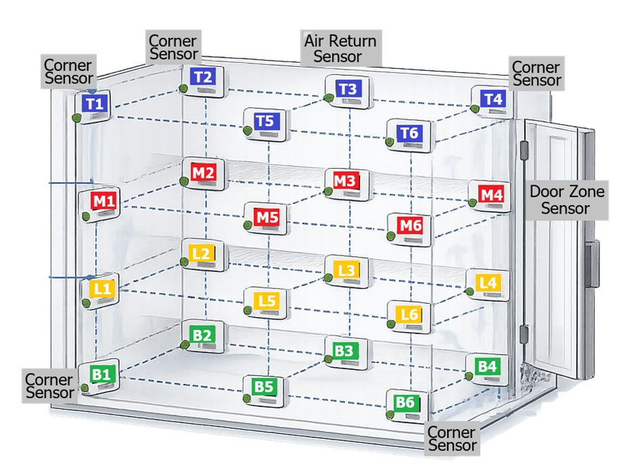
Sensor-placement strategy and quantity are addressed in Thermal Mapping Study Design and Qualification Strategy.
Physical Installation
Sensor installation should prevent:
- Contact with walls
- Contact with evaporators
- Contact with heaters
- Unintended immersion
- Movement
- Cable displacement
- Obstruction by loads
- Damage during door operation
- Interference with airflow
- Interference with routine operations
Mounting materials should remain suitable at the study temperature and should not damage equipment or stored materials.
Cable penetrations should not compromise door seals or enclosure integrity. Heat conducted through cables should be considered in extreme-temperature applications.
Mapping Software
Software may be used to:
- Configure loggers
- Start and stop studies
- Assign identifiers
- Synchronize time
- Download data
- Apply calibration corrections
- Generate calculations
- Produce graphs
- Create reports
- Export records
- Maintain audit trails
The software’s intended use should be defined. Functions affecting data accuracy, completeness, interpretation, or acceptance decisions should be verified.
Verification may include:
- User access
- Configuration controls
- Calculation accuracy
- Time handling
- Data transfer
- Missing-data indication
- Audit trail
- Report generation
- Export accuracy
- Backup
- Recovery
Vendor testing may support the assessment but does not replace evaluation of the site’s configured use.
Raw Data and Processed Data
Raw data should be retained in its original electronic form. Processed outputs may include:
- Spreadsheets
- Summary tables
- Graphs
- Heat maps
- Statistical calculations
- Qualification reports
Processed data should remain traceable to the original records and documented processing steps.
Exporting values to a spreadsheet does not make the spreadsheet the original record. Formulas, manual changes, filtering, excluded data, and rounding should be controlled and reviewed.
Data Integrity
Thermal-mapping data support qualification decisions and should remain complete, consistent, accurate, and retrievable. Controls should address:
- Unique user accounts
- Appropriate privileges
- Password control
- Audit trails
- Original-data retention
- Configuration records
- Time synchronization
- Secure transfer
- Controlled analysis
- Backup
- Recovery
- Record retention
- Review
FDA’s Data Integrity and Compliance With Drug CGMP guidance states that CGMP data should be reliable and accurate and that controls may be based on data-integrity risk.
Mapping files should not be renamed, edited, overwritten, or selectively deleted without controlled procedures and traceability.
Missing Data
Missing data may result from:
- Battery failure
- Memory exhaustion
- Sensor disconnection
- Communication failure
- Software error
- Download failure
- Incorrect start configuration
- Physical damage
- Logger malfunction
The protocol should define acceptable data completeness and the process for assessing gaps.
The assessment should consider:
- Duration of the gap
- Sensor location
- Study phase
- Nearby sensors
- Redundant coverage
- Challenge events
- Acceptance margin
- Study objective
Wireless communication gaps do not necessarily mean measurement data were lost when the logger stored readings locally. The buffered data should be reconciled after communication is restored.
Missing data should not be silently interpolated or excluded.
Outliers and Suspect Data
An unexpected reading should not be removed merely because it differs from nearby sensors. The investigation should consider:
- Sensor identity
- Sensor placement
- Physical contact
- Calibration status
- Battery condition
- Communication
- Door or access events
- Defrost
- Local airflow
- Equipment malfunction
- Nearby sensor behavior
- Repeatability
An outlier may represent an instrument failure, placement error, or genuine localized condition.
Exclusion requires documented technical justification and assessment of the qualification conclusion.
Instrument Qualification and Functional Verification
Mapping instrumentation should be shown to be suitable for its intended use. Verification may address:
- Hardware identification
- Channel operation
- Sensor compatibility
- Measurement range
- Configuration
- Sampling interval
- Time synchronization
- Memory
- Battery
- Communication
- Data buffering
- Data transfer
- Software calculations
- User access
- Audit trail
- Backup and recovery
Commercial calibration alone does not verify every configured software or data-handling function.
The required documentation should be scaled to instrument complexity, intended use, and risk.
Routine Instrument Control
The instrumentation program should address:
- Inventory
- Unique identification
- Calibration status
- Storage
- Battery management
- Cleaning
- Inspection
- Firmware version
- Software version
- User access
- Backup
- Repair
- Damage
- Retirement
Loggers should be stored under conditions that preserve calibration and battery performance.
Damaged instruments should be segregated until assessed, repaired, and returned to service through an approved process.
Change Control
Changes requiring assessment may include:
- New sensor technology
- Logger replacement
- Battery-type change
- Firmware update
- Software update
- Calibration-method change
- Calibration-range change
- Reference-standard change
- Sampling-interval change
- Wireless-network change
- Computer replacement
- Data-export change
- Calculation change
- Audit-trail change
- User-role change
- Backup or archive change
The assessment should determine whether calibration, functional verification, software testing, procedure revision, training, or study reassessment is required.
Common Instrumentation Weaknesses
Common weaknesses include:
- Treating accuracy and resolution as interchangeable
- Selecting instruments from displayed decimal places
- Applying fixed accuracy values without intended-use justification
- Calibrating outside the actual use range
- Using room-temperature calibration for ultra-low applications
- Omitting calibration uncertainty
- Claiming traceability without documenting the calibration chain
- Applying annual calibration without performance review
- Omitting as-found results
- Requiring or omitting post-study calibration without risk assessment
- Ignoring drift direction
- Failing to assess a calibration failure
- Using unsuitable sampling intervals
- Failing to synchronize logger clocks
- Allowing battery or memory exhaustion
- Treating wireless communication loss as automatic data loss
- Routing cables through door seals without assessment
- Retaining only exported spreadsheets
- Removing outliers without investigation
- Silently interpolating missing data
- Using uncontrolled spreadsheet calculations
- Failing to verify software calculations
- Selecting monitoring probes without mapping evidence
Conclusion
Thermal mapping requires more than placing calibrated loggers inside equipment. The complete measurement system must be suitable for the operating range, study objective, sampling requirements, environmental conditions, and qualification acceptance criteria.
Reliable results depend on appropriate sensor technology, calibrated logger electronics, justified sampling intervals, time synchronization, controlled deployment, secure data handling, and documented assessment of uncertainty, drift, missing data, and instrument failures.
Accuracy, resolution, precision, and uncertainty should remain distinct. Calibration establishes instrument performance against a reference, while uncertainty defines the remaining doubt associated with the reported result. Both must be considered when qualification data approach an acceptance limit.