

Stability Chambers: Design and Qualification
Stability chambers provide controlled environmental conditions for storing drug substances, drug products, packaging configurations, intermediates, and other samples included in approved stability programs. Most chambers regulate temperature and relative humidity simultaneously; specialized systems may also provide controlled light exposure or other environmental conditions.
The required chamber conditions must come from the approved stability protocol, regulatory strategy, product requirements, applicable market, and current guidance. Conditions such as 25 °C/60% RH, 30 °C/65% RH, 30 °C/75% RH, and 40 °C/75% RH are widely used examples, but no single condition set applies universally to every product, dosage form, package, climatic zone, or regulatory market.
Chamber qualification demonstrates that the installed equipment can create, maintain, monitor, record, and recover the approved environmental conditions throughout its defined storage volume. It does not establish the scientific adequacy of the stability program, analytical methods, sample intervals, batch selection, bracketing design, matrixing design, or shelf-life conclusion.
21 CFR 211.166 requires a written stability-testing program that includes storage conditions for samples retained for testing. ICH Q1A(R2) provides internationally recognized stability-testing principles and example conditions for new drug substances and products.
Stability Program and Chamber Qualification
The stability program defines:
- Products and drug substances included
- Batches
- Container-closure systems
- Storage conditions
- Sample quantities
- Pull intervals
- Test methods
- Acceptance criteria
- Study duration
- Bracketing or matrixing where applicable
- Excursion assessment
- Data review
- Shelf-life or retest-period conclusions
Chamber qualification separately establishes that the environmental equipment is suitable for providing the required storage conditions.
The distinction matters because:
- A qualified chamber does not make an inadequate stability protocol acceptable.
- A valid stability protocol does not establish that the chamber performs correctly.
- Chamber mapping does not replace stability-indicating analytical testing.
- Product stability data do not replace equipment qualification.
- An environmental excursion requires both equipment assessment and study-impact assessment.
The two systems should interface through approved procedures, sample inventories, monitoring records, alarm response, excursion management, and change control.
Intended Use and User Requirements
The intended-use statement should identify:
- Stability conditions to be supported
- Drug substances or products stored
- Container and packaging configurations
- Required sample capacity
- Chamber type
- Required temperature range
- Required relative-humidity range
- Required operating duration
- Maximum and minimum anticipated load
- Door-opening frequency
- Required recovery performance
- Independent monitoring requirements
- Alarm and escalation requirements
- Electronic-record requirements
- Backup-power expectations
- Redundant-conditioning expectations
- Qualified backup-chamber capacity
- Sample-transfer requirements
- Cleaning requirements
- Access-control requirements
- Photostability requirements where applicable
The User Requirements Specification should distinguish critical requirements from convenience features.
The system boundary may include:
- Chamber enclosure
- Insulation
- Doors and seals
- Shelves and racks
- Refrigeration system
- Heating system
- Humidification system
- Dehumidification system
- Water supply and treatment
- Condensate drainage
- Air-circulation system
- Temperature-control sensors
- Relative-humidity control sensors
- Independent monitoring probes
- Local controller
- Monitoring system
- Alarm system
- Electronic records
- Network interfaces
- Backup power
- Associated procedures
Types of Stability Chambers
Reach-In Chambers
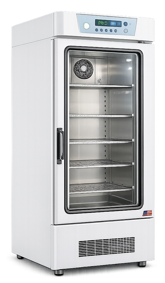
Reach-in stability chambers provide controlled conditions within a cabinet-style enclosure. They are commonly used for development studies, smaller commercial programs, supplementary conditions, retained samples, or specialized studies.
Potential advantages include:
- Compact footprint
- Defined shelf arrangement
- Relatively small controlled volume
- Independent operation
- Flexibility in assigning study conditions
Potential limitations include:
- Limited capacity
- Greater sensitivity to door openings
- Potential airflow obstruction from dense loading
- Rapid changes in humidity during access
- Dependence on one conditioning system
Walk-In Chambers
Walk-in stability chambers provide room-scale storage for larger programs and sample inventories.
Design considerations include:
- Insulated enclosure
- Personnel entry
- Emergency egress
- Multiple racks
- Three-dimensional distribution
- Large sample inventory
- Longer airflow paths
- Multiple conditioning units
- Multiple monitoring probes
- Larger door-opening disturbances
- Sample-transfer logistics
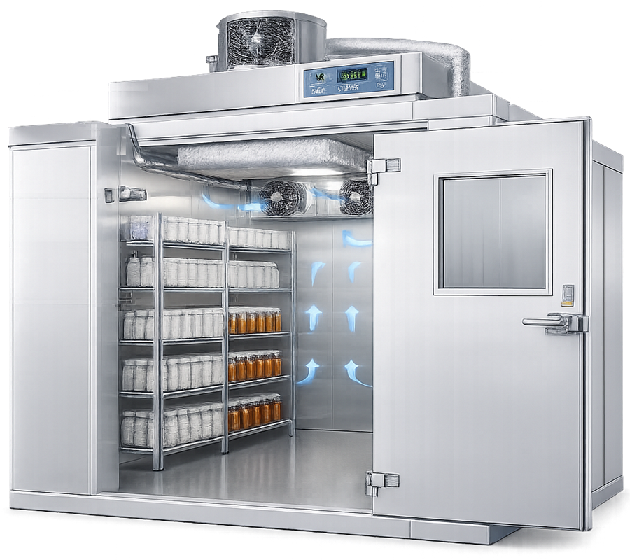
Multiple conditioning units do not automatically provide redundancy. Their independence, remaining capacity, shared utilities, power sources, controllers, and failure dependencies should be established.
Photostability Chambers
Photostability chambers expose samples to controlled visible and ultraviolet light while maintaining required thermal conditions. They may be used for studies designed according to ICH Q1B or another approved protocol.
Qualification may address:
- Visible-light source
- Ultraviolet source
- Spectral output
- Irradiance
- Exposure measurement
- Light distribution
- Sample orientation
- Distance from the light source
- Temperature control
- Airflow
- Timers
- Light-source aging
- Interlocks
- Electronic records
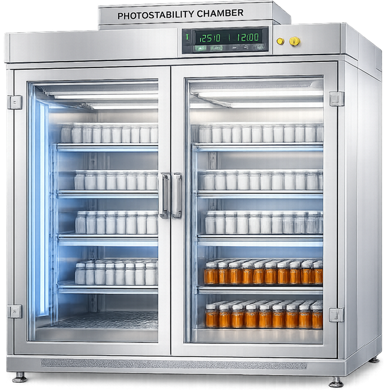
A conventional temperature-and-humidity chamber should not be represented as a qualified photostability chamber merely because internal lights are present.
Environmental-Control Architecture
A stability chamber coordinates heating, cooling, humidification, dehumidification, and air circulation.
Primary components may include:
- Refrigeration compressor
- Condenser
- Expansion device
- Cooling coil
- Electric or fluid heating coil
- Steam humidifier
- Ultrasonic humidifier
- Atomizing humidifier
- Dehumidification coil
- Desiccant system
- Circulation fan
- Supply and return plenums
- Temperature sensors
- Relative-humidity sensors
- Local controller
- Independent monitoring system
- Water supply
- Condensate drain
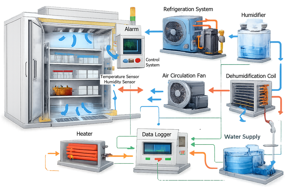
The exact architecture is manufacturer- and application-specific. Qualification should test the installed system rather than assume one control strategy applies to every chamber.
Temperature and Relative-Humidity Control Loops
Temperature and relative humidity are related but separate controlled parameters.
Temperature affects relative humidity because relative humidity expresses the amount of water vapor present relative to the amount the air could hold at that temperature. A temperature change can alter the relative-humidity reading even when the absolute moisture content remains unchanged.
The chamber controller may therefore coordinate:
- Cooling
- Reheating
- Humidification
- Dehumidification
- Fan operation
- Defrost
- Water management
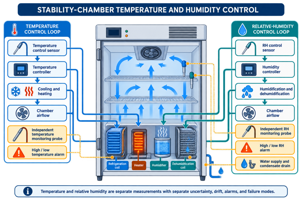
Temperature and relative humidity use separate sensors, controls, monitoring probes, alarms, uncertainty evaluations, and failure assessments even when one controller coordinates both parameters.
Temperature Control
Temperature regulation may use:
- Refrigeration
- Electric heating
- Hot-water heating
- Staged heating and cooling
- Modulating control
- Manufacturer-specific proportional control
Performance should be evaluated for:
- Stability
- Cycling
- Overshoot
- Undershoot
- Control near the setpoint
- Operation during humidification
- Operation during dehumidification
- Door recovery
- Load changes
- Ambient changes
Relative-Humidity Control
Humidity generation may use:
- Steam injection
- Ultrasonic generation
- Atomization
- Heated-water evaporation
- Other controlled moisture sources
Dehumidification may use:
- Cooling below the dew point followed by reheating
- Dedicated refrigeration coils
- Desiccant systems
- Dry-air dilution
- Other manufacturer-specific methods
Humidity performance should be evaluated for:
- Control stability
- Distribution
- Cycling
- Condensation
- Sensor drift
- Water-supply failure
- Dehumidification failure
- Door-opening recovery
- Operation at different temperature conditions
Water Supply and Condensate Management
The humidification system may depend on purified water, deionized water, softened water, potable water, or another specified supply.
The required water quality should be based on:
- Humidifier design
- Aerosol generation
- Mineral sensitivity
- Chamber-cleanliness requirements
- Sample protection
- Maintenance
- Manufacturer requirements
Water-system risks include:
- Supply interruption
- Low pressure
- Empty reservoir
- Scale
- Biofilm
- Blocked nozzles
- Heater failure
- Water-quality deterioration
- Leakage
- Overflow
- Pump failure
- Level-sensor failure
Condensate-management risks include:
- Blocked drain
- Frozen or restricted drain
- Trap failure
- Drain backflow
- Standing water
- Chamber leakage
- Uncontrolled microbial growth
- Corrosion
- Sensor wetting
Qualification should verify the relevant water-supply, level-control, drainage, alarm, and failure functions.
Airflow Distribution and Loading
Conditioned air must reach the approved sample-storage locations and return to the conditioning system without unacceptable obstruction.
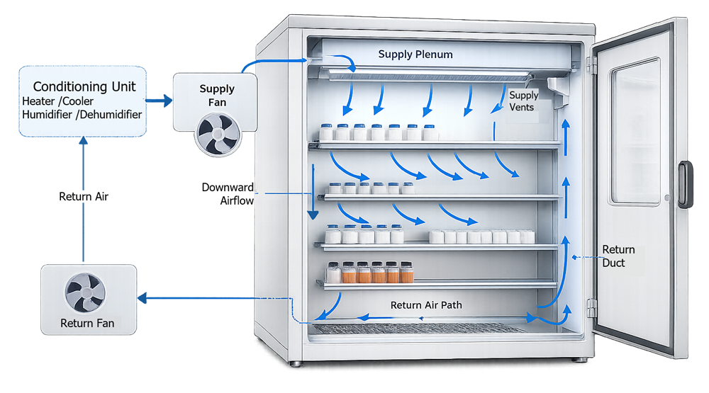
Stability-chamber airflow moves conditioned air across shelves and sample loads before returning it to the heating, cooling, humidification, and dehumidification components.
Temperature and humidity distribution can be affected by:
- Supply-air location
- Return-air location
- Fan capacity
- Shelf design
- Rack position
- Sample density
- Packaging geometry
- Large cartons
- Door location
- Chamber corners
- Wall clearances
- Maximum storage height
- Temporary staging
- Condensation
Operating procedures should define:
- Approved shelf and rack positions
- Maximum storage height
- Loading-density limits
- Wall clearance
- Supply-air clearance
- Return-air clearance
- Door-clearance zone
- Monitoring-probe clearance
- Prohibited storage areas
- Temporary-staging restrictions
A chamber should not be qualified using open wire shelves and then operated with unassessed solid trays, densely packed boxes, or racks that materially change airflow.
Thermal mass can slow temperature changes but does not correct poor airflow or humidity distribution.
Control Sensors and Independent Monitoring Probes
The chamber may contain separate sensors for:
- Temperature control
- Relative-humidity control
- Temperature monitoring
- Relative-humidity monitoring
- Refrigeration control
- Defrost
- Safety limits
- Water level
- Condensation detection
The control sensors regulate chamber operation. Independent monitoring probes provide evidence used for study oversight, alarm response, excursion assessment, and environmental records.
The control and monitoring functions may have different:
- Locations
- Technologies
- Calibration requirements
- Accuracy
- Response time
- Sampling interval
- Alarm delays
- Data retention
- Failure dependencies
Independent monitoring probes should be placed using mapping results and the monitoring objective.
A monitoring location should be:
- Within the qualified storage volume
- Representative of stored samples
- Stable across approved conditions
- Protected from damage
- Accessible for calibration
- Capable of meaningful alarm warning
- Unaffected by routine sample placement
The absolute highest or lowest reading from one mapping study is not automatically the best permanent monitoring location.
Relative-Humidity Sensor Considerations
Humidity measurement is generally more sensitive than temperature measurement to contamination, condensation, drift, and environmental history.
Sensor technologies may include:
- Capacitive sensors
- Resistive sensors
- Chilled-mirror devices
- Other manufacturer-specific technologies
Potential influences include:
- Condensation
- High-humidity exposure
- Chemical contamination
- Cleaning agents
- Water droplets
- Sensor aging
- Pressure
- Temperature
- Calibration history
- Sensor equilibration time
A humidity probe that becomes wet may require drying, evaluation, calibration, or replacement. A normal display after drying does not automatically establish that the sensor remained accurate.
Temperature and humidity uncertainty should be assessed separately. Their results should not be combined into one general “chamber accuracy” statement.
Door Openings and Recovery
Door openings introduce ambient air and disturb both temperature and humidity.
The magnitude and duration of the disturbance depend on:
- Door size
- Opening duration
- Number of openings
- Ambient temperature
- Ambient humidity
- Chamber volume
- Load
- Airflow
- Condition being maintained
- Sample-handling activity
- Sensor locations
- Sensor response times
Humidity may change more rapidly or recover differently than temperature.
A representative recovery test should define:
- Initial stabilized condition
- Load configuration
- Door used
- Opening duration
- Simulated sample activity
- Ambient conditions
- Mapping locations
- Temperature response
- Humidity response
- Alarm behavior
- Recovery criteria
- Maximum acceptable recovery time
Recovery should not be defined only by the controller display. Independent mapping or monitoring results should be assessed according to the study objective.
Alarm and Notification Strategy
Potential alarms include:
- High temperature
- Low temperature
- High relative humidity
- Low relative humidity
- Door open
- Power failure
- Refrigeration failure
- Heater failure
- Humidifier failure
- Dehumidifier failure
- Water-supply failure
- Low water level
- Drain or condensate alarm
- Fan failure
- Sensor failure
- Communication failure
- Monitoring-system failure
Alarm configuration should define:
- Initiating condition
- Setpoint
- Delay
- Deadband or hysteresis
- Priority
- Local annunciation
- Remote notification
- Escalation
- Acknowledgment
- Return-to-normal behavior
- Response procedure
- Event recording
Alarm limits should not simply duplicate chamber acceptance limits without considering normal cycling, measurement uncertainty, response time, allowable excursion, and time needed for corrective action.
Testing should verify:
- Detection of the initiating condition
- Correct configured threshold
- Correct delay
- Local audible and visual annunciation
- Transmission to the monitoring system
- Notification to the correct responders
- Acknowledgment and escalation
- Event recording
- Return-to-normal and reset
Detailed monitoring, alarm, electronic-record, and data-integrity controls are addressed in Temperature Monitoring, Alarm Systems, and Data Integrity.
Electronic Records and Data Integrity
Stability-chamber records may support regulatory submissions, expiration dating, study validity, excursion assessment, and product-lifecycle decisions.
The system may generate:
- Temperature records
- Relative-humidity records
- Alarm records
- Acknowledgments
- User actions
- Setpoint changes
- Configuration changes
- Audit trails
- Calibration records
- Sample-location records
- Transfer records
Controls should address:
- Unique user accounts
- Access roles
- Administrator privileges
- Time synchronization
- Audit trails
- Record review
- Data retention
- Data export
- Backup
- Recovery
- Interface verification
- Missing-data detection
- Local data buffering
- System availability
- Cybersecurity
- Change control
21 CFR 211.194 requires complete records of stability testing and periodic calibration records for applicable laboratory instruments. FDA’s Data Integrity and Compliance With Drug CGMP guidance supports risk-based controls intended to assure that GMP data are complete, consistent, and accurate.
A controller trend displayed on a screen is not adequate evidence unless required data can be retained, reviewed, retrieved, and protected throughout the record-retention period.
Qualification Strategy
Qualification should demonstrate that the installed chamber, conditioning system, controls, sensors, monitoring system, alarms, water system, racks, loading configuration, procedures, and contingency arrangements collectively support the intended use.
The general qualification lifecycle is addressed in Validation Life Cycle.
Chamber-specific qualification should demonstrate that:
- The installed configuration matches approved requirements.
- Temperature control operates correctly.
- Humidity control operates correctly.
- Environmental distribution is acceptable.
- Required storage conditions are supported.
- Door-opening recovery is acceptable.
- Alarms and notifications operate correctly.
- Failure and restart behavior are understood.
- Records are complete and retrievable.
- Backup and recovery operate as intended.
- Sample-transfer procedures are effective.
Design Review and Design Qualification
Design review should address:
- Required stability conditions
- Chamber capacity
- Reach-in or walk-in configuration
- Insulated enclosure
- Refrigeration capacity
- Heating capacity
- Humidification capacity
- Dehumidification capacity
- Airflow
- Shelf and rack layout
- Control sensors
- Monitoring probes
- Water supply
- Drainage
- Alarm architecture
- Electronic records
- Access control
- Backup power
- Conditioning redundancy
- Backup chamber
- Sample-transfer logistics
- Cleaning
- Maintenance access
- Vendor support
- Spare parts
- Obsolescence
Vendor specifications should be evaluated against the actual intended use. A manufacturer’s uniformity result may have been established under different conditions, loading, sensor placement, duration, or ambient environment and should not automatically replace site qualification.
Installation Qualification
Installation Qualification may verify:
- Manufacturer
- Model
- Serial number
- Equipment identification
- Installation location
- Chamber dimensions
- Insulation and enclosure
- Doors and seals
- Shelves and racks
- Refrigeration system
- Heating system
- Humidifier
- Dehumidification system
- Circulation fans
- Supply and return paths
- Temperature sensors
- Humidity sensors
- Monitoring probes
- Water supply
- Condensate drain
- Electrical supply
- Emergency power
- Alarm interfaces
- Network connections
- Software and firmware versions
- Configured parameters
- Calibration status
- Manuals and drawings
- Preventive-maintenance requirements
Walk-in-chamber IQ should also verify room construction, emergency egress, lighting, penetrations, rack arrangement, and facility interfaces.
Operational Qualification
Operational Qualification should challenge critical functions across the approved operating conditions.
Potential OQ tests include:
- Startup
- Initial stabilization
- Temperature setpoint verification
- Relative-humidity setpoint verification
- Heating
- Cooling
- Humidification
- Dehumidification
- Fan operation
- Fan failure
- Water-supply failure
- Drain failure where detectable
- Temperature-sensor failure
- Humidity-sensor failure
- High and low alarms
- Door-open alarm
- Power failure
- Communication failure
- Monitoring-system failure
- Automatic restart
- Manual restart where required
- Access control
- Configuration security
- Electronic records
- Audit trails
- Data buffering
- Backup and recovery
- Temperature and humidity mapping
- Door-opening recovery
Testing should verify failure response, alarm transmission, event recording, recovery, and required operator action.
Three-Dimensional Temperature and Humidity Mapping
Mapping should characterize both spatial and temporal behavior throughout the defined storage volume.
Temperature and humidity mapping locations should consider:
- Upper, middle, and lower levels
- Front, center, and rear
- Corners
- Door-adjacent locations
- Supply-air influence
- Return-air influence
- Remote locations
- Control-sensor locations
- Monitoring-probe locations
- Representative loaded racks
- Known areas of condensation
- Areas affected by external walls or ceiling
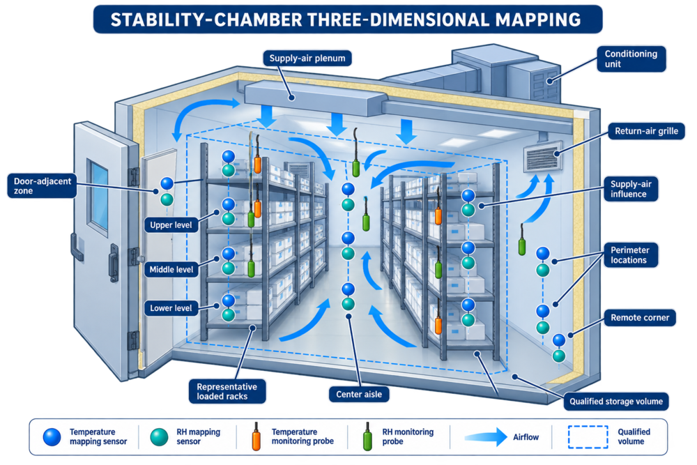
Three-dimensional mapping should evaluate temperature and relative humidity across the qualified storage volume, including racks, vertical levels, supply and return effects, doors, perimeter locations, and independent monitoring probes.
The number and location of sensors should be justified. No universal mapping-sensor count applies to every chamber.
The study duration should capture relevant:
- Heating and cooling cycles
- Humidification and dehumidification cycles
- Defrost
- Door disturbances
- Water-system operation
- Normal control behavior
- Environmental interaction
Temperature and humidity loggers may have different response times and sampling limitations. Their locations should be coordinated but need not be physically identical when the study design justifies another arrangement.
General mapping design is addressed in Thermal Mapping Study Design and Qualification Strategy. Logger selection, calibration, drift, response time, and uncertainty are addressed in Thermal Mapping Sensors, Data Loggers, and Measurement Uncertainty.
Empty and Loaded Mapping
Empty mapping can characterize inherent chamber distribution and control without load obstruction.
Representative-load mapping evaluates:
- Routine sample density
- Rack arrangement
- Packaging geometry
- Airflow obstruction
- Thermal mass
- Moisture interaction
- Monitoring-probe suitability
- Recovery
The required conditions should be justified rather than prescribed universally.
A simulated load should reproduce relevant obstruction and thermal characteristics. Empty cartons may represent airflow obstruction but not thermal mass. Water containers may provide thermal mass but may not represent cartons, blister packages, bottles, pouches, or secondary packaging.
Load diagrams should identify:
- Rack and shelf positions
- Sample-box locations
- Load density
- Clearances
- Mapping sensors
- Monitoring probes
- Prohibited storage zones
- Door-access route
Performance Qualification
Performance Qualification should demonstrate acceptable performance under approved routine or simulated-use conditions.
The scope may include:
- Representative sample loading
- Approved rack arrangement
- Routine access
- Normal control cycles
- Independent monitoring
- Alarm response
- Electronic-record review
- Execution by trained personnel
- Sample-inventory procedures
- Transfer procedures
The number and duration of studies should be justified according to intended use, chamber variability, operating cycles, risk, and existing OQ evidence. A universal three-run requirement should not be imposed without technical basis.
Equipment PQ does not validate the stability program or establish product shelf life.
Power Loss, Conditioning Failure, and Recovery
Different failures may produce different environmental responses.
Potential events include:
- Loss of normal power
- Loss of emergency power
- Refrigeration failure
- Heater failure
- Humidifier failure
- Dehumidifier failure
- Water-supply failure
- Fan failure
- Controller failure
- Monitoring-system failure
- Network failure
Qualification should assess:
- Alarm activation
- Remaining control capability
- Emergency-power transfer
- Controller restart
- Compressor restart delay
- Heater restart
- Humidity recovery
- Data buffering
- Missing-data detection
- Chamber holdover
- Sample-transfer decision point
- Recovery
- Return-to-service requirements
A chamber may maintain acceptable temperature temporarily while relative humidity is already outside its approved range. Failure response should evaluate both parameters.
Chamber Failure and Sample Transfer
The contingency procedure should define:
- Alarm responders
- Decision authority
- Backup-chamber identity
- Qualified condition
- Available capacity
- Sample-transfer priority
- Sample-location records
- Transport containers
- Environmental protection during transfer
- Chain of custody
- Exposure documentation
- Inventory reconciliation
- Study-impact assessment
- Return-to-service approval
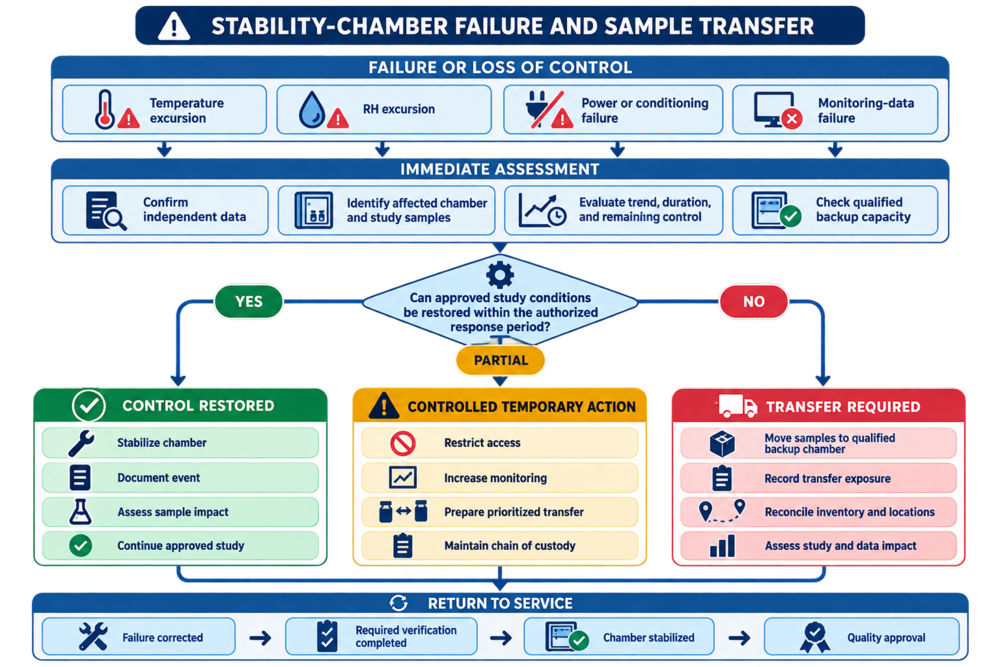
A stability-chamber failure requires confirmation of independent data, identification of affected samples, evaluation of remaining control, verification of backup capacity, and a documented decision to restore, temporarily control, or transfer the study inventory.
A backup chamber is not available merely because it exists. Its current qualification, condition, capacity, monitoring, alarms, and assigned studies should be confirmed.
Sample transfer should preserve:
- Sample identity
- Batch identity
- Study condition
- Pull schedule
- Location traceability
- Container status
- Chain of custody
- Exposure history
Acceptance Criteria and Data Evaluation
Acceptance criteria should be approved before execution and traceable to requirements.
Potential criteria include:
- Installed components match the approved design.
- Temperature control meets approved requirements.
- Relative-humidity control meets approved requirements.
- Required mapping locations remain within the approved criterion.
- The qualified storage volume is supported by mapping results.
- Door-opening recovery meets approved criteria.
- Alarms activate at approved settings.
- Remote notifications reach the correct responders.
- Water-supply and humidity failures produce the required response.
- Power-loss and restart behavior are acceptable.
- Electronic records are complete and retrievable.
- Backup and recovery are successful.
- Sample-transfer procedures are effective.
Data evaluation should address:
- Individual temperature results
- Individual humidity results
- Spatial gradients
- Control cycling
- Heating and cooling interaction
- Humidification and dehumidification interaction
- Door disturbances
- Recovery
- Condensation
- Missing data
- Sensor drift
- Measurement uncertainty
- Deviations
- Controller-to-reference differences
An average should not conceal an unacceptable individual location. Mean kinetic temperature should not be used automatically to dismiss an excursion, and it does not resolve an unacceptable relative-humidity condition.
Qualification Deviations and Release
Deviations should be assessed for:
- Test validity
- Data integrity
- Effect on related tests
- Effect on qualified storage volume
- Effect on monitoring locations
- Effect on stability studies
- Root cause
- Corrective action
- Need for repeat testing
- Effect on release
Release should occur only after:
- Required protocols are executed
- Deviations are resolved or acceptably dispositioned
- Calibration is current
- Qualified storage boundaries are established
- Racks and loading restrictions are approved
- Monitoring probes are installed
- Alarm settings are approved
- Electronic records are verified
- Backup and recovery are complete
- Backup-chamber arrangements are available
- Procedures are effective
- Personnel are trained
- The final report is approved
- Quality approval is obtained where required
Routine Operation and Continued Verification
Routine controls may include:
- Approved setpoints
- Alarm limits
- Rack and loading restrictions
- Access control
- Sample-location management
- Continuous temperature monitoring
- Continuous humidity monitoring
- Alarm response
- Excursion investigation
- Water-system checks
- Condensate inspection
- Door-seal inspection
- Fan inspection
- Refrigeration maintenance
- Humidifier maintenance
- Dehumidifier maintenance
- Sensor calibration
- Backup verification
- User-access review
- Audit-trail review
- Data-recovery testing
- Backup-chamber capacity review
Trend review should evaluate:
- Temperature excursions
- Humidity excursions
- Recovery time
- Control cycling
- Compressor runtime
- Water consumption
- Repeated low-water alarms
- Condensation
- Humidity-sensor drift
- Temperature-sensor drift
- Door-opening frequency
- Missing data
- Communication failures
- Maintenance frequency
- Repeated operator interventions
Change Control and Requalification
Potential changes include:
- Relocation
- Change in stability condition
- New intended use
- Rack modification
- Shelf modification
- Loading-density change
- Refrigeration repair
- Heater replacement
- Fan replacement
- Humidifier change
- Dehumidifier change
- Water-supply change
- Drain modification
- Control-sensor replacement
- Monitoring-probe replacement
- Controller replacement
- Alarm-setting change
- Software or firmware update
- Monitoring-system change
- Network change
- Emergency-power modification
- Extended shutdown
The impact assessment should determine whether existing evidence remains valid and whether additional testing is required.
Potential requalification may include:
- Installation verification
- Calibration
- Functional testing
- Alarm testing
- Targeted temperature mapping
- Targeted humidity mapping
- Comprehensive mapping
- Door-opening recovery
- Water-failure testing
- Power-loss testing
- Data-interface testing
- Backup and recovery
- Sample-transfer exercise
A like-for-like designation should be based on technical comparison. Matching a general component name does not establish equivalence of range, accuracy, capacity, response, materials, control behavior, software, or installation effect.
Repeated excursions, adverse trends, sensor drift, condensation, recurring equipment failures, or unreliable records can trigger requalification even when no formal design change occurred.
Risk-Based Requalification of GMP Equipment, Systems, and Utilities addresses the general trigger-to-scope decision process.
Common Qualification Weaknesses
Common weaknesses include:
- Treating example ICH conditions as universal
- Confusing chamber qualification with stability-program validation
- Qualifying temperature but not relative humidity
- Combining temperature and humidity accuracy into one statement
- Ignoring humidity-sensor drift and condensation
- Assuming multiple conditioning units provide redundancy
- Omitting water-supply and drain failures
- Relying on the controller display as proof of distribution
- Mapping only at one shelf level
- Using a universal sensor count or study duration
- Omitting representative loading
- Selecting monitoring probes without mapping evidence
- Testing only local alarm indication
- Failing to challenge humidification or dehumidification failure
- Omitting power-restoration behavior
- Treating acceptable temperature as proof that humidity remained acceptable
- Failing to verify backup-chamber capacity
- Transferring samples without preserving location and exposure records
- Using mean kinetic temperature to dismiss every excursion
- Ignoring missing monitoring data
- Performing backup without testing recovery
- Repeating failed tests without investigating the cause
- Returning a repaired chamber to service without verification
These weaknesses create gaps between environmental control, monitoring records, study-sample custody, excursion assessment, and regulatory stability data.
Conclusion
Stability-chamber qualification should demonstrate that the installed chamber, environmental-conditioning equipment, temperature and humidity controls, sensors, monitoring systems, alarms, racks, water system, electronic records, and contingency procedures collectively support the approved stability conditions.
A defensible program treats temperature and relative humidity as separate measurements, maps their distribution throughout the qualified storage volume, evaluates loading and door access, challenges conditioning and monitoring failures, verifies data integrity, and establishes controlled sample-transfer arrangements.
Routine monitoring, calibration, maintenance, alarm review, excursion assessment, change control, and risk-based requalification then provide continuing evidence that the chamber remains suitable for the approved stability program without confusing equipment performance with product-stability conclusions.