

Temperature Monitoring, Alarm Systems, and Data Integrity
Temperature-controlled equipment requires reliable monitoring to provide documented evidence that materials, products, and samples remain under approved storage conditions. The monitoring system must also detect unacceptable conditions, notify responsible personnel, preserve complete records, and support timely evaluation of temperature excursions.
This article addresses routine monitoring systems used with pharmaceutical refrigerators, freezers, cold rooms, warehouses, stability chambers, incubators, and other controlled-temperature equipment. It covers monitoring architecture, probe placement, alarm configuration, failure detection, electronic records, qualification, routine review, and system changes.
Detailed mapping-study design is addressed in Thermal Mapping Study Design and Qualification Strategy. Sensor technologies, calibration, data loggers, and measurement uncertainty are addressed in Thermal Mapping Sensors, Data Loggers, and Measurement Uncertainty.
Regulatory and Quality-System Basis
21 CFR 211.142 requires drug products to be stored under appropriate conditions of temperature, humidity, and light so that identity, strength, quality, and purity are not affected.
21 CFR 211.166 requires a written stability-testing program and specifies that stability results are used to determine appropriate storage conditions and expiration dates.
When automatic or electronic equipment performs a GMP function, 21 CFR 11.68 requires appropriate calibration, inspection, checking, computer-system controls, and data backup.
If electronic monitoring records are maintained in place of required paper records or are relied upon to perform regulated activities, the applicability of 21 CFR Part 11 should be formally assessed. Part 11 applicability should be based on the actual records and business practices rather than assumed solely because software is used.
FDA’s Part 11, Electronic Records; Electronic Signatures—Scope and Application explains FDA’s current approach to Part 11 scope and the continuing importance of applicable predicate-rule requirements.
FDA’s Data Integrity and Compliance With Drug CGMP: Questions and Answers states that CGMP data should be reliable and accurate and supports risk-based strategies for preventing and detecting data-integrity failures.
These requirements do not prescribe a universal monitoring-system design, recording interval, alarm delay, or number of probes. The selected controls should be scientifically justified for the equipment, materials, operating conditions, response capability, and associated risk.
Equipment Control and Independent Monitoring
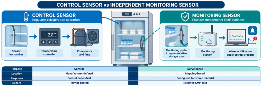
Temperature control and temperature monitoring are related but distinct functions.
The equipment control system regulates the controlled condition. It uses a control sensor, controller, and output devices such as compressors, heaters, fans, dampers, valves, or humidification equipment.
The monitoring system independently observes conditions, records data, evaluates alarm criteria, and provides evidence used for operational and quality decisions.
| Function | Equipment control system | Independent monitoring system |
|---|---|---|
| Primary purpose | Regulate temperature or another controlled parameter | Record conditions and detect unacceptable performance |
| Typical sensor | Control sensor connected to the equipment controller | Independent calibrated monitoring probe |
| Primary output | Compressor, heater, fan, valve, or other control command | Historical record, alarm, notification, or report |
| Record use | Equipment operation and diagnostic review | GMP review, excursion evaluation, and storage evidence |
| Failure concern | Loss or instability of environmental control | Undetected excursion, missing data, or unreliable records |
| Typical qualification focus | Control accuracy, sequencing, operating limits, and failure response | Data acquisition, alarms, records, access, interfaces, backup, and recovery |
A single sensor or platform may perform both functions, but independence should not be claimed unless common failure modes have been evaluated. Shared power, wiring, transmitters, networks, controllers, software, or databases may cause control and monitoring functions to fail simultaneously.
The design should identify:
- Which sensor controls the equipment
- Which sensor generates the official monitoring record
- Which system generates the alarm
- Where the original electronic record resides
- Which system determines the official alarm state
- Which dependencies are shared
- How failures are detected
- What operators do when either function is unavailable
Pharmaceutical Refrigerators and Freezers: Design and Qualification provides equipment-specific examples of control and monitoring sensor arrangements.
Monitoring-System Architecture
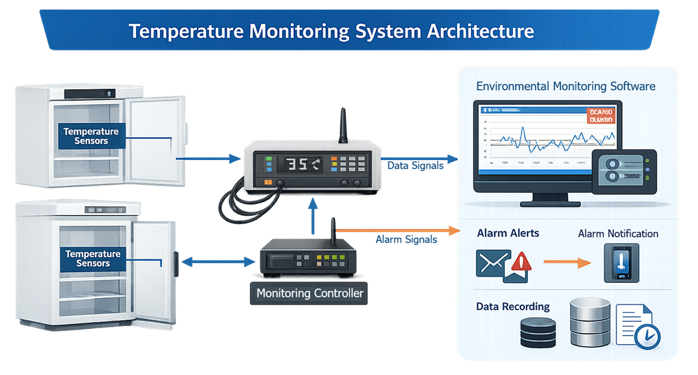
A temperature-monitoring system may be local to one unit or centralized across multiple rooms, chambers, and storage devices.
Typical components include:
- Temperature or humidity probes
- Signal transmitters
- Input modules or data-acquisition devices
- Local displays
- Gateways
- Programmable controllers
- Environmental monitoring software
- Application and database servers
- Network infrastructure
- Alarm-notification services
- Email, text, voice, or mobile interfaces
- Historical data repositories
- Reporting tools
- Backup and archival systems
- Time-synchronization services
- Uninterruptible power supplies
- Administrative workstations
The architecture should distinguish several separate paths:
- Measurement path from probe to recorded value
- Alarm-evaluation path from measurement to alarm state
- Notification path from alarm state to responsible personnel
- Acknowledgment path from user to the monitoring system
- Data-storage path from acquisition to the permanent record
- Backup path from production data to protected backup
- Recovery path from backup to a usable restored system
Successful data recording does not prove that notification worked. Successful notification does not prove that the historical record is complete. Each path should be assessed and tested according to its intended function.
Centralized platforms may share infrastructure with building management systems, environmental monitoring systems, enterprise networks, identity-management systems, or external communication services. System boundaries, ownership, interfaces, and common dependencies should be defined.
Facility Automation and Monitoring Architecture and Concepts addresses broader facility-automation architecture and shared infrastructure.
Monitoring-Probe Location
Routine probe locations should be based on scientific and operational evidence rather than convenience or proximity to an available cable route.
Potential inputs include:
- Thermal-mapping results
- Qualified storage volume
- Consistent warm and cold locations
- Product or material sensitivity
- Equipment control-sensor location
- Air-supply and return locations
- Doors and access openings
- Shelves, racks, and pallet positions
- Normal loading arrangements
- Defrost behavior
- Heating or cooling sources
- Airflow obstructions
- Probe response characteristics
- Representative product exposure
- Previous alarm and excursion history
The warmest mapped location is not automatically the only correct monitoring location. For some applications, both warm and cold conditions can affect stored materials. Freezing-sensitive refrigerated products may require detection of the coldest credible condition, while frozen materials may require surveillance of the warmest condition.
Large rooms, warehouses, multiple HVAC zones, cryogenic vessels, and complex chambers may require more than one routine probe. The number and location should reflect the possibility that one probe cannot represent all qualified storage areas or independent control zones.
Mapping should include a sensor at or near each proposed monitoring location so that its relationship to surrounding storage conditions can be evaluated. The final location should be documented on an approved drawing or location record.
Cold Rooms and Walk-In Freezers: Design and Qualification and GMP Warehouse Temperature Mapping and Qualification address monitoring-location challenges for larger controlled spaces.
Probe Configuration and Response
Routine probes may be installed as direct air sensors or within a thermal buffer such as glycol, glass beads, or a purpose-designed simulation medium.
An unbuffered air probe responds quickly to changes in chamber air temperature. It can detect equipment disturbances promptly but may also respond to short door openings, defrost cycles, or local airflow changes that do not represent the temperature of stored material.
A buffered probe responds more slowly and may approximate the thermal behavior of a stored product more closely. However, buffering can delay alarm activation and may conceal rapid changes that are important to the intended use.
Probe configuration should consider:
- Material thermal mass
- Container type
- Air-to-product temperature relationship
- Expected excursion duration
- Required alarm-response time
- Door-opening frequency
- Defrost behavior
- Probe and buffer response time
- Alarm delay
- Equipment failure rate
- Applicable stability information
Buffering should not be used merely to suppress nuisance alarms. The buffer type, volume, material, container, location, and response characteristics should be defined and controlled.
Probe replacement should preserve the approved configuration. Substituting a different sensor, buffer volume, transmitter, protective sheath, or mounting arrangement can change measurement response and should be assessed through change control.
Sampling and Recording Intervals
The sampling interval determines how often the sensor is read. The recording interval determines how often a value is retained. These intervals may be identical, but some systems sample frequently and store only selected, averaged, minimum, maximum, or exception values.
The configuration should define:
- Sensor scan interval
- Alarm-evaluation interval
- Historical recording interval
- Use of instantaneous or averaged values
- Data compression rules
- Minimum and maximum retention
- Handling of repeated values
- Treatment of communication interruptions
- Local buffering capacity
- Upload behavior after reconnection
- Time assigned to delayed records
- Report-resolution limitations
The interval should be short enough to detect and characterize credible temperature changes. A long recording interval can underestimate excursion duration, fail to capture a short extreme, or make the exact event sequence uncertain.
A shorter interval creates more data but does not correct poor probe placement, inadequate accuracy, weak alarm logic, or incomplete review.
Alarm evaluation should not depend on a slower reporting or trending interval unless that behavior is intended, documented, and tested.
Alarm Strategy
An alarm is a configured system response to a defined condition. Alarm strategy should establish which conditions require detection, when an event becomes reportable, who is notified, what action is required, and how the event is closed.
Alarm configuration may include:
- High-temperature limit
- Low-temperature limit
- High-humidity limit
- Low-humidity limit
- Alert level
- Action level
- Alarm delay
- Deadband or hysteresis
- Rate-of-change alarm
- Sensor failure
- Out-of-range signal
- Communication failure
- Power failure
- Door-open alarm
- Low battery
- Server or service failure
- Data-storage failure
- Backup failure
- Notification failure
Alarm limits should be derived from approved storage requirements, product or material risk, equipment performance, measurement uncertainty, and the time available for response.
Alert and Action Levels
An alert level provides early notification of a developing or unusual condition before an action limit is reached. It can support operational intervention without automatically classifying the event as a confirmed storage excursion.
An action level identifies a condition requiring defined response, documentation, and potential material-impact assessment.
Separate alert and action levels are useful only when:
- Each level has a defined purpose
- Personnel understand the required response
- The configured difference is technically meaningful
- Measurement uncertainty and normal variation are considered
- The system distinguishes the two conditions clearly
- Alert events are not ignored merely because the action level was not reached
A single alarm limit may be appropriate when separate levels provide no practical or risk-control benefit.
Alarm Delays
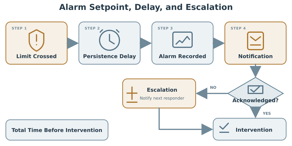
An alarm delay requires the condition to remain beyond the configured limit for a defined period before the alarm is activated or notification is sent.
Delays can prevent repeated alarms from brief door openings, defrost cycles, or other understood operating events. However, a delay also postpones detection and response.
The delay should be justified using:
- Material or product stability
- Equipment failure characteristics
- Door-opening studies
- Defrost profiles
- Probe response time
- Expected operator-response time
- Backup storage availability
- Measurement interval
- Mapping and recovery results
The total time before intervention may include:
Alarm delay + system-processing time + notification time + acknowledgment time + travel and response time
Evaluating only the configured alarm delay understates the actual exposure before corrective action begins.
Deadband and Hysteresis
Deadband or hysteresis prevents rapid switching between normal and alarm states when the measured value fluctuates near a limit.
For example, a high alarm may activate at one temperature but remain active until temperature falls below a separate reset value. This behavior should be defined and tested.
Excessive hysteresis can delay alarm clearance or conceal continued marginal conditions. Insufficient hysteresis can create repeated alarm activation and clearance events.
Latching and Automatic Clearance
A latched alarm remains active until it is acknowledged or reset, even if the measured value returns to the acceptable range. A nonlatched alarm may clear automatically when the condition ends.
Automatic clearance should not remove the historical record of:
- Alarm activation
- Maximum or minimum value
- Alarm duration
- Return to normal
- Acknowledgment
- Comments or response
- User identity
- Time of each event
Alarm Suppression, Inhibition, and Shelving
Some systems permit alarms to be disabled, suppressed, inhibited, bypassed, or temporarily shelved during maintenance or known operating conditions.
These functions require controls such as:
- Restricted authorization
- Documented reason
- Defined start time
- Defined expiration time
- Visible indication of the disabled state
- Audit-trail recording
- Independent review where appropriate
- Confirmation after restoration
- Prevention of indefinite suppression
A disabled alarm should not appear operational. The system should make suppressed or bypassed points readily identifiable.
Notification, Acknowledgment, and Escalation
Alarm generation and notification are separate functions. A monitoring system may correctly identify an alarm while a failed email server, cellular gateway, telephone service, network connection, or notification application prevents the message from reaching personnel.
Notification design should define:
- Primary recipient
- Secondary recipient
- Escalation sequence
- Escalation timing
- After-hours coverage
- Weekend and holiday coverage
- Required acknowledgment
- Acceptable acknowledgment method
- Response responsibility
- Backup communication method
- Handling of unreachable recipients
- Maximum permitted response time
- Documentation requirements
Acknowledging an alarm confirms receipt. It does not establish that the condition was corrected or that affected material is acceptable.
Alarm closure should be separate from acknowledgment where the system supports both functions. Closure should confirm that:
- The condition ended or was controlled
- Required operational action was completed
- Affected materials were identified
- The event was documented
- Required investigation was initiated
- Required quality review was completed
Escalation should continue when acknowledgment is not received within the approved period. If acknowledgment stops escalation, testing should confirm that an accidental or unauthorized acknowledgment cannot terminate the response without traceability.
Power, Communication, and System Failures
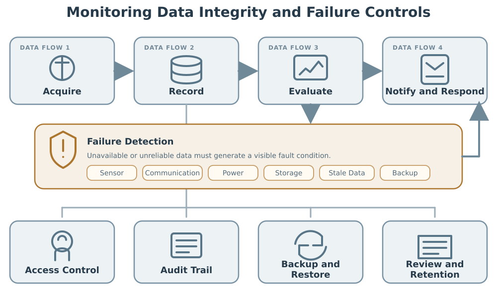
A monitoring system should detect failures that could prevent measurement, recording, alarm evaluation, notification, or retrieval.
Credible failures include:
- Monitoring-probe failure
- Open or shorted sensor circuit
- Transmitter failure
- Input-module failure
- Controller failure
- Gateway failure
- Network interruption
- Wireless signal loss
- Server shutdown
- Database unavailability
- Full storage volume
- Application-service failure
- Time-service failure
- Local power failure
- Facility power failure
- Uninterruptible-power-supply depletion
- Cellular or email service failure
- Failed local data upload
- Backup failure
The system should distinguish an acceptable environmental condition from an unavailable measurement. A frozen display, repeated stale value, flat signal, missing data, or communication fault should not be reported as evidence that temperature remained acceptable.
Failure controls may include:
- Bad-signal indication
- Communication-loss alarm
- Stale-data detection
- Local data buffering
- Store-and-forward capability
- Redundant communication paths
- Redundant servers
- Uninterruptible power
- Generator support
- Secondary monitoring device
- Manual monitoring procedure
- Controlled material transfer
- Defined recovery sequence
The permitted duration of local buffering should exceed a justified credible communication outage. Testing should verify what happens when the buffer becomes full and whether restored data retain their original acquisition timestamps.
Data Integrity and Electronic Records
Monitoring records may support material disposition, stability-study validity, investigation conclusions, and evidence of compliance with approved storage conditions. The records should therefore remain complete, accurate, attributable, contemporaneous, consistent, enduring, and available.
ALCOA+ Principles and Implementation describes these data-integrity attributes in greater detail.
The complete monitoring record may include:
- Raw measurements
- Engineering units
- Probe identity
- Equipment or location identity
- Acquisition timestamps
- Alarm events
- Alarm-state transitions
- Acknowledgments
- User comments
- Configuration changes
- Suppression or bypass events
- Communication failures
- Missing-data indicators
- Audit trails
- Calculated results
- Reports
- Review and approval records
- Metadata needed to interpret the record
A graphical trend or PDF report may not be the complete original record. The system assessment should identify which data, metadata, and audit trails are required to reconstruct the event and evaluate the reliability of the reported result.
User Access and Authority
Access should be limited according to assigned responsibilities. Typical roles may include:
- Viewer
- Operator
- Alarm responder
- Reviewer
- System administrator
- Metrology or calibration user
- Quality reviewer
Permissions should control the ability to:
- View current conditions
- Acknowledge alarms
- Enter alarm comments
- Close events
- Change alarm limits
- Change alarm delays
- Disable or suppress alarms
- Configure probes
- Change recording intervals
- Modify reports
- Manage users
- Change system time
- Delete or archive records
- Restore data
- Modify interfaces
Shared accounts should not be used for actions that require attribution. Administrative access should be restricted and periodically reviewed. Routine operational work should not require unrestricted administrator privileges.
Audit Trails
Audit trails should record changes or actions that affect regulated data, interpretation, or system operation.
Relevant events include:
- Alarm-limit changes
- Delay changes
- Probe additions or removals
- Scaling changes
- Unit changes
- Recording-interval changes
- Point disablement
- Alarm suppression
- User-role changes
- Time changes
- Data corrections
- Record deletion attempts
- Configuration import or restoration
The audit trail should identify what changed, the previous value, the new value, who made the change, and when it occurred. A reason for change should be captured when necessary to understand or approve the action.
Audit-trail review should be based on data and system risk. It should focus on meaningful events rather than mechanical review of every low-risk system entry.
Time Synchronization
Accurate and consistent timestamps are necessary to reconstruct temperature events, alarms, notifications, acknowledgments, equipment failures, and material movement.
Controls should address:
- Authoritative time source
- Time zone
- Daylight-saving-time behavior
- Permitted clock adjustment
- Automatic synchronization
- Loss of time-service communication
- Local device clocks
- Server and database clocks
- Timestamps applied to buffered data
- Audit trail for manual time changes
Systems should not create duplicate, missing, reordered, or ambiguous records during daylight-saving changes or loss of synchronization.
Calculations and Data Processing
Monitoring software may calculate averages, minimums, maximums, excursion durations, mean kinetic temperature, or time outside limits.
Qualification should verify:
- Calculation formulas
- Units and conversions
- Time-period selection
- Boundary conditions
- Treatment of missing data
- Treatment of invalid values
- Rounding
- Report filters
- Alarm-duration calculation
- Daylight-saving and time-zone behavior
- Recalculation after data correction
Processed results should remain traceable to the underlying measurements.
Data Review
Routine review should be designed around the intended use of the record.
Review may include:
- Completeness of expected data
- Missing or invalid readings
- Alarm events
- Alert events
- Communication failures
- Disabled or suppressed points
- Unexplained flat signals
- Unusual cycling
- Slow recovery
- Adverse temperature trends
- Probe drift
- Repeated acknowledgments without corrective action
- Audit-trail events
- Unreviewed excursions
- Open investigations
Reviewing only values that exceeded an alarm limit may miss degraded performance, repeated near-limit operation, missing records, unauthorized changes, or failures that prevented alarm generation.
Backup, Restore, and Record Retention
Backup protects monitoring records from loss, corruption, or system failure. A successful backup job does not prove that the data can be restored accurately and used.
The backup strategy should define:
- Data and configuration included
- Backup frequency
- Backup type
- Storage location
- Retention period
- Encryption where applicable
- Access control
- Monitoring of backup failures
- Separation from the production system
- Restoration responsibility
- Restoration sequence
- Verification after restoration
Restore testing should demonstrate that selected records, metadata, alarm history, audit trails, and configuration can be recovered in a complete and usable form.
Disaster-recovery planning should address more than restoration of historical data. It should define how monitoring and alarms are maintained while the primary system is unavailable.
Record-retention arrangements should preserve readability, context, and retrieval throughout the required retention period. System replacement or software obsolescence should not make historical records inaccessible.
Alarm Response and Temperature-Excursion Assessment
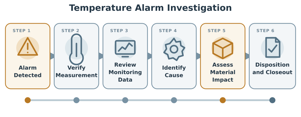
An alarm initiates response; it does not determine material disposition.
Initial response should include:
- Confirm alarm receipt
- Identify affected equipment or area
- Verify the current measured condition
- Check for sensor or communication failure
- Review local equipment status
- Determine whether doors are open
- Check power and utilities
- Protect or transfer affected materials when required
- Document immediate actions
- Notify responsible quality personnel when applicable
The event should then be characterized using available records:
- Start time
- End time
- Maximum or minimum temperature
- Duration outside the approved range
- Alarm delay
- Time of notification
- Time of acknowledgment
- Time corrective action began
- Equipment operating state
- Door-opening history
- Defrost status
- Power status
- Probe condition
- Communication status
- Materials and lots present
- Location of materials within the equipment
A confirmed temperature excursion should be evaluated using approved product or material requirements, stability information, cumulative exposure where applicable, and the actual limitations of the available data.
Mean kinetic temperature should not be applied automatically to justify an excursion. Its use requires a scientifically appropriate stability model, adequate data, and an approved decision framework.
The investigation should distinguish among:
- Actual environmental excursion
- Localized condition at the monitoring point
- Probe failure
- Calibration failure
- Communication failure
- Alarm-configuration error
- Notification failure
- Operational error
- Missing or unreliable data
Absence of reliable monitoring data is not evidence that storage conditions were acceptable.
Qualification and Verification
Qualification should be based on intended use, system complexity, GxP impact, supplier evidence, configuration risk, interfaces, and reliance on electronic records.
The qualification package may include:
- Intended-use statement
- System boundary
- GxP and Part 11 assessment
- User Requirements Specification
- Risk assessment
- Supplier assessment
- Architecture and data-flow diagrams
- Configuration specification
- Installation verification
- Functional testing
- Requirements traceability
- Deviation records
- Release report
- Procedures
- Training
- Approved configuration baseline
Installation Verification
Installation verification may include:
- Hardware and software identification
- Software and firmware versions
- Probe and transmitter identification
- Probe locations
- Network connections
- Servers and database
- Alarm gateways
- Power supplies
- Uninterruptible power supplies
- Backup configuration
- Time synchronization
- User roles
- Interfaces
- Environmental requirements
- Calibration status
- System documentation
Functional Testing
Functional testing should challenge both normal functions and credible failures.
Testing may include:
- Correct sensor-to-equipment association
- Correct engineering units
- Measurement transmission
- Historical data recording
- Recording interval
- High alarm
- Low alarm
- Alert level
- Action level
- Alarm delay
- Hysteresis
- Latching and reset
- Local annunciation
- Remote notification
- Escalation
- Acknowledgment
- Alarm closure
- Sensor failure
- Out-of-range signal
- Communication loss
- Network interruption
- Power interruption
- Server restart
- Local buffering
- Data upload after reconnection
- Missing-data indication
- User permissions
- Unauthorized action prevention
- Audit-trail generation
- Report generation
- Calculation accuracy
- Time synchronization
- Backup
- Restoration
Testing should verify the complete end-to-end alarm path from the physical or simulated condition through generation, notification, receipt, acknowledgment, escalation, recording, and review.
A message appearing on one screen does not demonstrate that the remote notification and escalation process works.
Probe Verification Against Mapping
Qualification should confirm that each monitoring probe is installed at its approved location and that the location is supported by mapping evidence.
The mapping study should also evaluate the monitoring probe or a colocated calibrated reference so that the relationship between the permanent probe and surrounding mapped conditions is understood.
Performance Verification
Performance verification may confirm operation under routine conditions, including:
- Normal equipment cycling
- Representative load
- Door openings
- Defrost
- Expected network traffic
- After-hours notification
- User response
- Routine report generation
- Data review
- Alarm documentation
The objective is to demonstrate that the technical system and associated procedures function together under the intended operating arrangement.
Routine Operation and Continued Verification
Routine controls should maintain confidence in the monitoring system after release.
Controls may include:
- Sensor calibration
- Probe-location inspection
- Alarm challenge testing
- Notification-path testing
- Escalation-list review
- User-access review
- Audit-trail review
- Backup monitoring
- Restore testing
- Data-capacity monitoring
- Time-synchronization checks
- Interface monitoring
- Battery replacement
- Uninterruptible-power-supply testing
- Cybersecurity assessment
- Software and firmware maintenance
- Periodic record review
- Alarm and excursion trending
Alarm recipients and escalation lists should be reviewed whenever responsibilities change. A technically functional notification system can still fail operationally when messages are directed to inactive accounts, obsolete telephone numbers, or personnel who are no longer responsible.
Alarm testing frequency should consider system risk, previous failures, supplier recommendations, site procedures, and the ability of the system to detect internal faults.
Change Control
Changes that can affect monitoring, alarms, or records should be assessed before implementation unless managed under an approved emergency-change process.
Potential changes include:
- Probe replacement
- Probe relocation
- Buffer change
- Transmitter replacement
- Calibration-range change
- Alarm-limit change
- Alarm-delay change
- Recording-interval change
- Equipment setpoint change
- Sensor scaling change
- Software or firmware update
- Server replacement
- Database migration
- Network modification
- Notification-service change
- Interface modification
- User-role change
- Time-source change
- Backup change
- Report change
- Cybersecurity patch
- Equipment relocation
- Shelving or load change
- Monitoring-system replacement
The assessment should determine whether the change requires:
- Documentation update
- Calibration
- Configuration verification
- Alarm retesting
- Interface testing
- Security testing
- Data-migration verification
- Backup and restore testing
- Targeted thermal mapping
- Monitoring-location reassessment
- Partial or comprehensive requalification
A replacement described as like-for-like should be supported by comparison of range, accuracy, response time, output, configuration, communication protocol, software compatibility, mounting, and failure behavior.
Periodic Review
Periodic review should determine whether the monitoring system remains suitable for its intended use and whether the approved state remains supported.
Review inputs may include:
- Changes
- Deviations
- Alarm history
- Excursion history
- Missing data
- Communication failures
- Notification failures
- Probe failures
- Calibration history
- Sensor drift
- Access review
- Audit-trail review
- Disabled or suppressed alarms
- Backup status
- Restore-test results
- System capacity
- Software and firmware status
- Cybersecurity changes
- Vendor support
- Obsolescence
- Open corrective actions
- Qualification status
- Mapping and monitoring-location changes
Periodic review should not be limited to confirming that calibration and preventive maintenance were completed. It should evaluate performance, records, configuration, security, infrastructure, and operating practices together.
Common Monitoring-System Weaknesses
Common weaknesses include:
- Control and monitoring functions treated as independent without evaluating shared failures
- Monitoring probes placed for convenience rather than mapping evidence
- Only one probe used for a large or multi-zone area without justification
- Buffered probes used solely to prevent nuisance alarms
- Alarm limits copied from the storage range without considering uncertainty or response time
- Alarm delays selected without evaluating total intervention time
- Remote notification assumed from successful local alarm activation
- Acknowledgment treated as corrective action
- Alarm suppression permitted without authorization or expiration
- Communication loss displayed as an acceptable repeated value
- Missing data not detected
- Buffered data assigned incorrect timestamps after reconnection
- Shared accounts used for alarm acknowledgment
- Administrators performing routine operations
- Audit trails enabled but not reviewed
- Reports retained without underlying data or metadata
- Backup performed without restore testing
- System time changes not controlled
- Alarm-recipient lists not maintained
- Software changes implemented without impact assessment
- Probe replacement classified as like-for-like without technical comparison
- Alarm review limited to excursions beyond configured limits
These weaknesses can create a false appearance of environmental control while reducing the reliability of the records used for material and quality decisions.
Conclusion
Temperature monitoring systems must do more than display current temperature. They should provide reliable measurement, complete records, effective alarm detection, controlled notification, documented response, and evidence suitable for evaluating stored materials.
A defensible system distinguishes equipment control from independent monitoring, places probes using mapping evidence, justifies alarm limits and delays, detects measurement and communication failures, protects electronic records, and verifies the complete alarm and data path.
Qualification, calibration, access control, audit-trail review, backup and recovery, alarm trending, change control, and periodic review then provide continuing evidence that the monitoring system remains suitable for its intended use.