

Facility Automation and Monitoring Architecture and Concepts
Purpose and Scope
Facility automation architecture defines how sensors, controllers, supervisory systems, networks, data repositories, alarm services, and supporting infrastructure work together to control and document GMP facility conditions.
Architecture must establish more than a list of installed components. It should define:
- System and subsystem boundaries
- Allocation of control and monitoring functions
- Data sources and destinations
- Control-command paths
- Alarm-generation and notification paths
- Electronic-record locations
- Interface ownership
- Shared infrastructure and common dependencies
- Failure behavior
- Manual operating provisions
- Backup and recovery arrangements
- Time synchronization
- Redundancy
- Cybersecurity dependencies
The architecture should be evaluated according to intended function and data use. A controller maintaining room pressure, an EMS recording that pressure, a historian retaining the data, and a notification platform communicating an alarm may constitute one operational chain even when supplied and maintained as separate systems.
This article addresses the technical architecture and its documentation. The broader distinction between BMS, EMS, control, monitoring, alarming, and recording functions is addressed in Facility Automation and Monitoring Overview. Qualification requirements are addressed separately in Qualification and Verification of Facility Automation Systems.
Architecture as an Operating Model
An architecture document should explain how the facility operates under:
- Normal conditions
- Startup and shutdown
- Occupied and unoccupied modes
- Production and nonproduction modes
- Local or manual control
- Maintenance conditions
- Communication interruption
- Server unavailability
- Power interruption
- Instrument failure
- Recovery from failure
A diagram that shows only connected boxes is insufficient when it does not identify:
- Which component performs the control logic
- Which system generates the official GMP record
- Where alarms are evaluated
- Which communication paths are required
- Which functions continue after network or server loss
- Which shared components create common failure modes
- Who owns each interface and supporting service
The installed architecture may be physically distributed while appearing centralized on an operator screen. Qualification, maintenance, change control, and incident response must be based on the actual arrangement.
Logical Architecture Layers
Facility automation can be organized into logical layers. These layers support understanding and documentation, but they do not necessarily represent separate physical systems.
Field-Device Layer
The field-device layer interacts directly with facility equipment and environmental conditions.
It may include:
- Temperature sensors
- Relative-humidity sensors
- Differential-pressure transmitters
- Airflow sensors
- Particle counters
- Utility instruments
- Equipment-status contacts
- Limit switches
- Current switches
- Variable-frequency drives
- Control valves
- Dampers
- Actuators
- Relays
- Local indication
Field devices originate measurements or execute commands. Their location, range, accuracy, calibration, environmental suitability, failure indication, and signal type affect every downstream function.
A value displayed by a server cannot be more reliable than the measurement chain that produced it.
Control and Monitoring Layer
This layer contains the logic used to control equipment or independently evaluate monitored conditions.
Components may include:
- Direct digital controllers
- Programmable logic controllers
- Equipment-local controllers
- Remote input/output modules
- BMS controllers
- EMS acquisition units
- Particle-monitoring controllers
- Embedded equipment controllers
- Local alarm logic
Control logic should normally remain close enough to the controlled equipment to support continued operation when a supervisory server or higher-level network is unavailable.
Monitoring logic may reside in:
- A dedicated acquisition unit
- An EMS server
- A monitoring controller
- An instrument
- A BMS controller
- A separate alarm-processing application
The architecture should identify the exact location of each critical calculation, comparison, delay, interlock, alarm, and control sequence.
Network and Interface Layer
Communication services connect field devices, controllers, servers, databases, and external applications.
They may include:
- Controller networks
- Monitoring networks
- Ethernet infrastructure
- Serial communication
- Fieldbus networks
- Wireless communication
- Network switches
- Routers
- Firewalls
- Gateways
- Protocol converters
- Interface engines
- Application programming interfaces
- Message brokers
- Remote-access connections
This is a logical layer, not necessarily a single physical level between field devices and controllers. A field device may communicate directly with a controller, while servers and controllers communicate through several network segments.
The architecture should show actual communication paths and should distinguish:
- Control traffic
- Monitoring data
- Alarm traffic
- Configuration traffic
- User-access traffic
- Backup traffic
- Time-synchronization traffic
- Remote vendor access
Data and Supervisory Layer
This layer provides centralized visibility, data handling, configuration, and supervisory functions.
Components may include:
- BMS servers
- EMS servers
- Supervisory applications
- Operator workstations
- Engineering workstations
- Web servers
- Application servers
- Data historians
- Databases
- Alarm-notification servers
- Reporting applications
- Interface servers
- Virtual machines
The supervisory display should not be assumed to contain the actual control logic. Loss of a BMS server may remove operator visibility while local controllers continue maintaining HVAC conditions.
Conversely, a server failure may interrupt monitoring records, alarms, reports, or notification even when physical control continues normally.
Quality and Business-Use Layer
Data from the automation architecture may support:
- Routine operational review
- Environmental review
- Alarm assessment
- Deviation investigation
- Product-impact assessment
- Batch or room disposition
- Trend reporting
- Qualification
- Periodic review
- Requalification decisions
- Regulatory inspection
- Management reporting
Applications in this layer may present data originating elsewhere. The architecture should identify whether they retain controlled copies, transform information, or only display information obtained from another system.
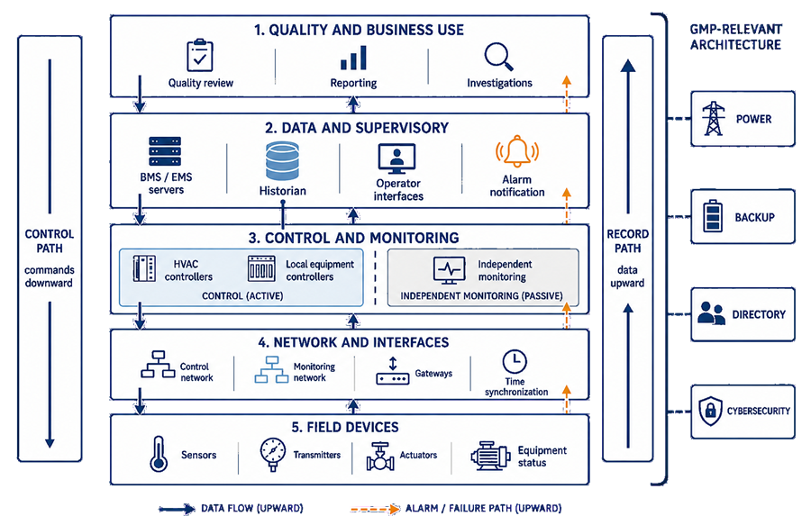
Facility automation combines field measurement, local control, independent monitoring, supervisory applications, data retention, and quality use. The architecture should distinguish the downward control path from the upward record and alarm paths while identifying infrastructure shared across the complete system boundary.
Control and Monitoring Segregation
Control and monitoring are different functions even when implemented within the same platform.
A control path typically includes:
- Sensor or transmitter
- Controller input
- Control algorithm
- Controller output
- Actuator or drive
- Mechanical response
- Feedback confirming the resulting condition
A monitoring path typically includes:
- Sensor, instrument, or transferred value
- Data-acquisition function
- Limit or alarm evaluation
- Time-stamped recording
- Display and trending
- Notification
- Review and investigation
Segregation may be achieved through:
- Separate sensors
- Separate sensor outputs
- Separate input modules
- Separate controllers
- Separate networks
- Separate applications
- Separate databases
- Functionally separated configurations within one platform
The required degree of segregation should be risk-based.
Independent monitoring may be important when loss or bias of the control measurement could otherwise remain undetected. For example, a BMS sensor used to control room pressure and a separate EMS sensor used to record and alarm the pressure provide greater detection capability than two applications using the same upstream transmitter.
However, separate systems are not automatically independent. They may share:
- Pressure tubing or reference locations
- Electrical power
- Network switches
- Virtual infrastructure
- Time services
- Directory services
- Gateways
- Databases
- Notification services
Independence claims should identify both segregated elements and remaining common dependencies.
System and Subsystem Boundaries
The architecture should define the complete boundary necessary to achieve intended operation and reliable records.
A system boundary may include:
- Field instruments
- Signal wiring
- Input/output modules
- Controllers
- Actuators
- Local panels
- Operator interfaces
- Servers
- Virtual machines
- Databases
- Historians
- Network components
- Gateways
- Notification services
- Time services
- Directory services
- Backup infrastructure
- Remote-access components
- Supporting procedures
- Responsible personnel
Subsystem boundaries may be used to separate:
- GMP-controlled areas from non-GMP areas
- HVAC control from environmental monitoring
- Individual air-handling systems
- Utility monitoring
- Alarm notification
- Reporting
- Historian functions
- Shared infrastructure
Boundary documentation should identify for every component:
- Function
- Physical or virtual location
- System owner
- Technical owner
- Data owner
- GMP significance
- Configuration authority
- Maintenance responsibility
- Qualification responsibility
- Failure effect
- Upstream and downstream dependencies
- Applicable change-control requirements
Supporting infrastructure should not be excluded merely because it is managed by information technology rather than engineering.
Architecture Documentation Set
A single high-level diagram rarely provides sufficient detail. Architecture documentation may include:
- System-context diagram
- Layered architecture diagram
- Physical network diagram
- Logical network diagram
- Controller and panel architecture
- Instrument and point inventory
- Server and virtual-machine inventory
- Software and firmware inventory
- Data-flow diagram
- Interface inventory
- Alarm-path diagram
- Time-synchronization diagram
- Backup and recovery architecture
- User and authentication architecture
- Cybersecurity-zone diagram
- Power and redundancy diagram
- Manual-operation description
- Responsibility matrix
Documentation should use consistent component names and identifiers across requirements, design documents, configuration records, drawings, qualification protocols, procedures, and maintenance records.
Unexplained differences between documents make it difficult to determine whether the installed system matches the approved design.
Data Sources, Flow, and Transformation
For each GMP-relevant data element, the architecture should show its progression from the source to its final use.
The path may include:
- Physical measurement
- Signal conversion
- Input scaling
- Controller processing
- Communication transfer
- Interface mapping
- Database ingestion
- Calculation or aggregation
- Historian retention
- Display or reporting
- Quality review
- Archival
Data may be changed through:
- Scaling
- Unit conversion
- Averaging
- Filtering
- Rounding
- Compression
- Exception-based recording
- Calculation
- Alarm-delay logic
- Derived values
- Time-zone conversion
- Manual transcription
Each transformation should be defined where it affects interpretation, alarms, reports, or regulated records.
The architecture should identify:
- Original data source
- Official GMP record
- Authoritative time stamp
- Recording frequency
- Display refresh frequency
- Expected transfer latency
- Metadata retained
- Quality or validity flags
- Missing-data representation
- Record-retention location
- Report source
A displayed point may appear current even when the last successful update occurred several minutes earlier. Interfaces should provide a visible indication of stale, invalid, substituted, or unavailable data where that distinction affects decisions.
Interface Ownership and Control
Interfaces are frequent sources of hidden responsibility gaps.
For every interface, document:
- Source system
- Destination system
- Business purpose
- Data owner
- Technical owner
- Configuration owner
- Point mapping
- Data type
- Engineering unit
- Scaling and precision
- Transfer direction
- Transfer frequency
- Time-stamp source
- Protocol
- Security controls
- Expected latency
- Buffering
- Retry behavior
- Duplicate handling
- Missing-data handling
- Failure alarm
- Recovery method
- Reconciliation requirements
- Change-control responsibility
Ownership should cover the complete interface rather than stopping at each system boundary.
For example:
- The BMS owner may control the source point.
- The automation or information-technology function may maintain the gateway.
- The EMS owner may control destination mapping.
- Quality may own the use of the resulting record.
One accountable role should coordinate changes and failures across the complete data path.
Data Historian Architecture
A historian receives and retains time-series data for trending, review, reporting, and investigation.
The architecture should define whether the historian is:
- Embedded within the BMS or EMS
- A separate application
- A shared enterprise service
- The official GMP record
- A controlled copy of data retained elsewhere
- An engineering-only troubleshooting resource
Historian configuration may determine:
- Which points are recorded
- Recording frequency
- Exception or deadband rules
- Data compression
- Retention duration
- Time-stamp source
- Data quality flags
- Calculations
- Aggregation
- Archive behavior
- User access
- Record export
Compression or exception-based recording can reduce storage but may omit intermediate changes. Its suitability should be evaluated against intended record use.
The architecture should also distinguish:
- Current-value display
- Controller trend
- Supervisory trend
- Historian record
- Reported value
- Archived record
These outputs may not contain identical data or timestamps.
Alarm and Notification Paths
Alarm handling may involve several components:
- A sensor detects the condition.
- A controller or monitoring application evaluates the limit.
- Alarm logic applies delay, priority, mode, or suppression.
- The alarm is recorded.
- The condition is displayed.
- A notification service sends a message.
- A recipient acknowledges or responds.
- The event is reviewed and closed through the applicable procedure.
The architecture should identify where each function occurs.
Alarm generation should be distinguished from notification. A notification-service failure may prevent a message from reaching personnel without removing the original alarm from the BMS or EMS.
The design should address:
- Alarm-source availability
- Communication-loss alarms
- Notification-service health
- Escalation failure
- Unacknowledged alarms
- Alarm buffering
- Duplicate notifications
- Return-to-normal messages
- Loss of mobile or external communication
- Manual response when automatic notification is unavailable
Alarm acknowledgment does not constitute investigation or documented closure.
Time Synchronization
Reliable time is necessary to reconstruct relationships among:
- Environmental conditions
- Equipment events
- Alarms
- Operator actions
- Manufacturing activities
- Door openings
- Maintenance
- Deviations
- Audit-trail entries
The architecture should define:
- Authoritative time source
- Time-server hierarchy
- Systems and devices receiving synchronized time
- Synchronization frequency
- Permitted clock deviation
- Time zone
- Daylight-saving-time handling
- Coordinated universal time use
- Local-controller clocks
- Server and database time
- Interface time stamps
- Behavior after loss of synchronization
- Detection and alarm of time-service failure
- Correction of an incorrect clock
- Documentation of time changes
The source timestamp should be retained where possible. Replacing it with the destination-system receipt time can obscure interface delay or communication interruption.
Time synchronization is both an operational and data-integrity dependency.
Network Interruption and Communication Failure
The architecture should define what happens when communication is interrupted between:
- Field devices and controllers
- Controllers and supervisory servers
- BMS and EMS
- Servers and historians
- Alarm servers and notification services
- Workstations and applications
- Primary and remote sites
- Systems and time services
- Systems and directory services
Possible effects include:
- Loss of supervisory visibility
- Stale displayed values
- Loss of remote commands
- Interrupted data recording
- Missing alarms
- Delayed notification
- Loss of synchronized time
- Inability to authenticate users
- Incomplete reports
- Failure to transfer buffered data
Local control should continue where appropriate and technically supported. Continued control does not establish that monitoring, alarm communication, or record retention also continued.
The design should specify:
- How communication loss is detected
- Which alarms remain available
- Whether values retain a valid-data flag
- Whether local data are buffered
- Buffer capacity
- Behavior when the buffer becomes full
- Transfer after reconnection
- Duplicate prevention
- Chronological reconciliation
- Required review after recovery
- Manufacturing restrictions during the interruption
Manual and Local Operation
Manual operation is a planned operating state, not an informal workaround.
Manual provisions may be necessary during:
- Supervisory-server failure
- Network interruption
- Controller replacement
- Sensor failure
- Maintenance
- Cybersecurity isolation
- Recovery activities
- Planned automation outage
The architecture and procedures should define:
- Functions available locally
- Authorized personnel
- Local access controls
- Permitted manual commands
- Safe operating limits
- Independent indication
- Temporary monitoring
- Frequency of manual readings
- Alarm limitations
- Documentation requirements
- Communication with operations and quality
- Criteria for manufacturing continuation
- Restoration to automatic mode
- Post-restoration verification
Manual mode should be clearly indicated. Uncontrolled overrides, forced inputs, disabled alarms, or temporary setpoint changes can defeat qualified functions and should be restricted, time-limited, documented, and reviewed.
A manual record created during system unavailability should be reconciled with recovered electronic data where appropriate. It should not be silently replaced by later electronic information.
Power, Redundancy, and Availability
Redundancy should be based on required availability and failure consequences.
Possible provisions include:
- Uninterruptible power supplies
- Emergency power
- Redundant power supplies
- Redundant controllers
- Duty and standby equipment
- Redundant servers
- Database clustering
- Redundant network paths
- Redundant switches
- Independent monitoring sensors
- Failover notification services
- Geographic backup
- Spare controllers or instruments
Redundancy does not eliminate failure risk. It introduces additional concerns:
- Failover logic
- Synchronization between redundant components
- Hidden failure of the standby component
- Common power or network dependencies
- Configuration inconsistency
- Split-brain conditions
- Alarm behavior during transfer
- Periodic failover testing
- Return to the primary component
The design should distinguish between:
- High availability
- Fail-safe operation
- Backup
- Disaster recovery
These controls serve different purposes and should not be treated as interchangeable.
Backup, Restore, and Disaster Recovery
Backup protects configuration and records from loss. Restore returns selected data or configuration. Disaster recovery restores service after a major interruption.
The architecture should identify what is backed up, including:
- Databases
- Historian records
- Server configurations
- Controller programs
- BMS and EMS applications
- Graphics
- Point databases
- Alarm configurations
- Interface mappings
- User and role configurations
- Reports
- Audit trails
- Virtual-machine images
- Encryption keys or certificates where applicable
The strategy should define:
- Backup frequency
- Backup type
- Retention
- Storage location
- Segregation from the operating environment
- Encryption
- Access
- Monitoring of backup success
- Restoration priorities
- Recovery-time objectives
- Recovery-point objectives
- Restoration testing
- Record reconciliation after recovery
A successful backup job does not demonstrate successful restoration. Restore capability should be periodically verified using controlled testing.
Cybersecurity Dependencies
Cybersecurity controls protect system availability, integrity, and authorized use. They also create dependencies that must be included in the architecture.
Relevant components may include:
- Firewalls
- Network segmentation
- Antivirus or endpoint protection
- Application allowlisting
- Patch-management services
- Directory services
- Multifactor authentication
- Remote-access gateways
- Security-monitoring tools
- Certificate services
- Vulnerability-management tools
- Backup protection
- Vendor-support connections
Architecture documentation should identify:
- Security zones
- Permitted communication paths
- Required ports and protocols
- Trust relationships
- Administrative-access paths
- Remote-access controls
- Authentication dependencies
- Logging and monitoring
- Security-event escalation
- Isolation capability
- Recovery after a cybersecurity event
Cybersecurity controls should not be implemented without evaluating their operational effect. A firewall change, expired certificate, blocked service, forced restart, or endpoint-protection update can interrupt control visibility, data transfer, alarm notification, or system access.
Conversely, operational continuity should not be used to justify uncontrolled remote access, obsolete software, shared accounts, or unsegmented networks.
Architecture Review and Design Decisions
Architecture review should evaluate whether the design:
- Supports the intended facility-control strategy
- Separates functions where independence is required
- Identifies the official record
- Avoids unnecessary single points of failure
- Detects critical failures
- Supports continued local control
- Preserves data during interruptions
- Provides reliable alarm escalation
- Maintains synchronized time
- Supports backup and recovery
- Provides controlled manual operation
- Restricts unauthorized access
- Supports maintenance and future expansion
- Can be qualified and periodically reviewed
Important design decisions and assumptions should be documented, including:
- Use of shared versus separate sensors
- Location of control logic
- Use of local control during network failure
- Selection of the official historian
- Data-compression strategy
- Alarm-evaluation location
- Required monitoring independence
- Redundancy decisions
- Manual-monitoring provisions
- Cybersecurity zoning
- Inclusion or exclusion of supporting infrastructure
Rejected alternatives should be retained where they explain a significant risk decision or boundary choice.
Architecture Qualification Considerations
Architecture documentation provides the basis for qualification but does not replace functional testing.
Testing may verify:
- Component installation
- Point-to-point signal paths
- Control-command paths
- Monitoring paths
- Independent measurement
- Interface mapping
- Data transformations
- Historian recording
- Time stamps
- Alarm generation
- Alarm notification
- Communication-loss detection
- Data buffering
- Recovery and reconciliation
- Controller operation after server loss
- Local and manual operation
- Power interruption
- Redundancy and failover
- Backup and restoration
- Access restrictions
- Remote-access controls
- Cybersecurity-related failure behavior
Testing should follow the complete path needed for the intended function. Confirming that a value appears on a workstation does not verify its source, scaling, timestamp, storage, alarm behavior, or recovery.
Maintaining Architecture Documentation
Architecture documentation should remain controlled throughout the system lifecycle.
Changes that may require updates include:
- Added or relocated sensors
- Controller replacement
- Logic modification
- Server migration
- Virtual-platform changes
- Network redesign
- Firewall-rule changes
- New interfaces
- Point remapping
- Historian replacement
- Database changes
- Notification-platform changes
- Revised time services
- Backup changes
- Authentication changes
- Cybersecurity controls
- Redundancy changes
- Remote-access changes
- System retirement
Change assessment should determine which drawings, inventories, specifications, risk assessments, qualification records, procedures, and recovery plans require revision.
Periodic review should confirm that the documented architecture still represents the installed configuration and actual data use.
Common Architecture Weaknesses
Common weaknesses include:
- Treating a vendor network drawing as complete GMP architecture documentation
- Showing components without showing data, control, and alarm paths
- Failing to identify where control logic resides
- Assuming a supervisory server performs local control
- Claiming independent monitoring despite shared upstream dependencies
- Failing to identify the official GMP record
- Omitting historian configuration and data compression
- Excluding gateways and interface engines from the boundary
- Undefined interface ownership
- Missing communication-loss alarms
- Displaying stale data as current
- Assuming local control means all system functions remain available
- Failing to define manual operation
- Unverified data buffering and reconciliation
- Unsynchronized controller, server, and application clocks
- Treating backup as equivalent to disaster recovery
- Installing redundancy without testing failover
- Excluding directory, power, virtualization, or network services from dependency assessment
- Allowing cybersecurity changes without automation impact assessment
- Maintaining obsolete diagrams that no longer represent the installed system
Maintaining a Reliable Facility-Automation Architecture
A defensible architecture should establish:
- What each component does
- Where every critical function resides
- How control commands reach facility equipment
- How monitoring data reach the official record
- Where alarms are generated and communicated
- Which functions are segregated
- Which dependencies are shared
- How interfaces are owned and controlled
- How data are transformed and retained
- How system time is established
- What continues during network or server failure
- How missing or buffered records are reconciled
- How manual operation is controlled
- How backup, recovery, redundancy, and cybersecurity support continued operation
- How the installed configuration is documented and maintained
The objective is an architecture that remains understandable during normal operation, qualification, change, failure, investigation, and recovery. Complexity may be necessary, but undocumented complexity is an avoidable source of operational and compliance risk.