

Airflow, Filtration, and Pressure Verification
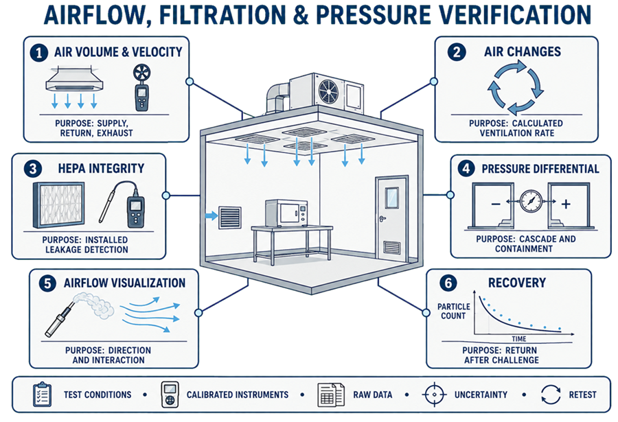
Airflow, filtration, and pressure verification provides documented evidence that an operating HVAC system produces the intended air quantities, filtration integrity, pressure relationships, airflow behavior, particle-control conditions, and recovery performance in the spaces it serves.
The work converts HVAC design intent and functional operation into measured room-level evidence. It may include supply, return, transfer, and exhaust airflow; air velocity; air-change calculations; installed-filter-system leakage testing; room differential pressure; airflow visualization; nonviable-particle classification; and recovery testing.
These tests are related, but they do not demonstrate the same condition:
- An acceptable air-change rate does not establish suitable airflow patterns.
- A passing installed HEPA-filter-system leakage test does not establish room classification.
- A stable closed-door pressure differential does not establish control during door openings or representative operation.
- A passing nonviable-particle classification result does not demonstrate viable environmental control.
- Successful functional HVAC OQ does not independently establish room-level performance.
The approved HVAC qualification strategy should define which tests apply, their sequence, test conditions, acceptance basis, and how the results integrate with HVAC operational qualification, cleanroom classification, and environmental performance qualification.
Purpose and Verification Boundary
This verification determines whether the installed and operating HVAC system produces specified physical conditions at the room, zone, filter, terminal, and boundary level. Depending on design and intended use, the scope may include:
- Supply-air volume at each terminal and total room supply
- Return- and exhaust-air quantities
- Transfer airflow where it supports the pressure or containment strategy
- Average velocity and velocity uniformity in defined unidirectional-airflow zones
- Air-change-rate calculations
- Reconciliation of room and system air balance
- Installed HEPA- or ULPA-filter-system leakage testing
- Filter pressure drop or resistance where required
- Room-to-room and room-to-corridor differential pressure
- Airflow direction at doors, pass-throughs, transfer openings, and process interfaces
- Airflow visualization under defined static and dynamic conditions
- Nonviable airborne-particle classification
- Recovery after a defined particle challenge
- Comparison of installed indications with calibrated reference measurements
- Supporting measurements for environmental qualification
This article does not replace the separate requirements and methods applicable to viable environmental monitoring, temperature or humidity mapping, detailed airflow smoke studies, or environmental performance qualification.
Several activities may be executed within one protocol package. A combined format should preserve the individual objective, method, raw data, acceptance criteria, deviations, and conclusion for each test.
Regulatory and Technical Basis
21 CFR 211.46 requires adequate ventilation and, where appropriate, equipment for controlling air pressure, microorganisms, dust, humidity, and temperature. It also addresses air filtration, recirculated air, and exhaust systems.
For aseptic-processing facilities, FDA’s Sterile Drug Products Produced by Aseptic Processing—Current Good Manufacturing Practice provides recommendations concerning HEPA-filtered air, pressure relationships, airflow patterns, installed-filter integrity testing, airflow visualization, and cleanroom qualification.
The principal ISO references are:
- ISO 14644-1:2015, which specifies classification of air cleanliness by airborne-particle concentration
- ISO 14644-2:2015, which specifies minimum requirements for a monitoring plan that provides evidence of cleanroom performance related to airborne-particle concentration
- ISO 14644-3:2019, which provides cleanroom and clean-zone test methods
ISO 14644-3 includes test methods addressing airflow, air-pressure difference, installed-filter-system leakage, airflow direction and visualization, recovery, temperature, humidity, and other performance attributes. These methods support verification when the corresponding test is selected by agreement, specification, risk assessment, or another applicable requirement.
This distinction is essential:
- A requirement established by an applicable regulation, approved specification, or adopted standard forms part of the acceptance basis.
- A test method describes how specified evidence may be obtained.
- A practical field recommendation may improve execution but is not automatically a normative requirement.
ISO 14644 does not establish one universal air-change rate, room differential pressure, airflow velocity, recovery time, filter-leak limit, or testing frequency for every GMP room.
Acceptance criteria must be derived from the applicable standard, approved requirements, contamination-control or containment strategy, process needs, facility design, operating state, and risk assessment.
Test Strategy and Sequence
Testing should follow a defined sequence because adjustment or failure of one attribute can affect the validity of later results. A typical sequence is:
- Confirm prerequisites and controlled test conditions.
- Verify instruments, configurations, and reference documents.
- Confirm system stabilization and operating mode.
- Measure airflow volume or velocity.
- Reconcile supply, return, transfer, and exhaust quantities.
- Calculate air-change rates where specified.
- Perform installed-filter-system leakage testing where required.
- Measure room differential pressures and verify airflow direction.
- Perform airflow visualization under defined conditions.
- Perform nonviable-particle classification.
- Perform recovery testing where required.
- Evaluate combined results, deviations, repairs, adjustments, and retesting.
The sequence may be modified based on system design and risk.
For example, a filter leak should normally be corrected before relying on downstream particle-classification or recovery results. Airflow rebalancing can affect room pressure, filter-face velocity, airflow visualization, particle performance, and recovery. Affected tests should therefore be reassessed after balancing adjustments.
Pre-requisites
Testing should begin only when the installed configuration and environmental conditions are sufficiently controlled for the results to represent the system being qualified. Typical prerequisites include:
- Approved requirements and room data sheets
- Approved HVAC qualification or verification plan
- Defined system, room, filter, terminal, and boundary identifiers
- Accepted installation baseline
- Accepted functional OQ or documented readiness for the tests being executed
- Current as-built drawings, airflow schematics, and pressure-cascade diagrams
- Completed testing, adjusting, and balancing sufficient to support verification
- Final filter type, installation, and operating condition
- Released control-system configuration and operating modes
- Current calibration for installed critical instruments
- Current calibration for test instruments
- Required utilities available
- Cleaned rooms and controlled construction status
- Defined as-built, at-rest, or operational state
- Defined occupancy and activity conditions
- Defined door, pass-through, and process-equipment conditions
- Defined exhaust, local extraction, and transfer-air states
- Stable temperature, humidity, airflow, and pressure control
- Approved protocol and predetermined acceptance criteria
- Safety assessment for aerosol generation, smoke, access, ladders, and work near operating equipment
- Controlled disposition of open items that could affect the results
The protocol should define stabilization using observable conditions rather than an arbitrary waiting period alone. Stable trends, completed operating-mode transition, and established pressure relationships provide stronger evidence than elapsed time by itself.
If balancing remains in progress, filters have been disturbed, critical doors are unavailable, construction is incomplete, or the operating mode does not represent the approved test condition, affected testing should be deferred.
Test Conditions
Each result should be linked to the actual conditions present during testing. The record should identify, as applicable:
- Date and time
- Room and HVAC system
- As-built, at-rest, or operational state
- Occupancy and activities
- Door and pass-through positions
- Supply, return, transfer, and exhaust operating states
- Local-exhaust or process-equipment status
- Operating mode and setpoints
- Filter condition and relevant pressure drop
- Temperature and relative humidity
- Outdoor or seasonal conditions where material
- Recent cleaning, shutdown, maintenance, filter replacement, or balancing
- Temporary controls, overrides, or disabled alarms
- Deviations from the approved condition
Terms such as “at rest” and “operational” should be defined in the protocol. They should not be inferred solely from whether the room happens to be occupied during testing.
A closed-door baseline is generally necessary, but it does not represent every operating condition. Door openings, pass-through use, local-exhaust operation, equipment movement, and personnel activity should be evaluated when they can materially affect product protection or containment.
Instruments, Calibration, and Suitability
Instruments should be suitable for the expected range, resolution, accuracy, response time, operating environment, and test method. Depending on scope, instruments may include:
- Air-capture or flow hood
- Thermal or vane anemometer
- Pitot tube or equivalent traverse equipment
- Micromanometer or differential-pressure meter
- Aerosol generator
- Aerosol photometer
- Discrete-particle-counter system suitable for the selected filter-leak test
- Optical airborne-particle counter
- Temperature and relative-humidity instruments
- Timing device
- Smoke or tracer-visualization equipment
- Tachometer, barometer, or other supporting instruments where required
The protocol or supporting package should record:
- Instrument type
- Manufacturer and model
- Serial or asset number
- Measurement range and resolution
- Relevant accuracy or uncertainty information
- Calibration status and due date
- Calibration standard or traceability basis
- Required pre-use and post-use checks
- Zero, background, reference, or functional checks
- Instrument settings and sample rate
- Correction factors
- Engineering units
- Limitations affecting interpretation
A current calibration label does not establish suitability by itself. A calibrated instrument can still have inadequate range, resolution, response, sampling characteristics, probe geometry, or uncertainty for the intended measurement.
If an instrument is found outside calibration, damaged, unstable, contaminated, or incorrectly configured, an impact assessment should identify all potentially affected results and determine whether they require invalidation or repeat testing.
Air-Volume Measurement
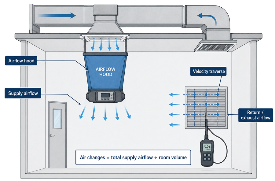
Air-volume testing determines the quantity of air supplied, returned, exhausted, or transferred at defined points.
Terminal Measurements
A flow hood is commonly used for supply diffusers and return or exhaust grilles when the hood and terminal geometry are compatible.
The method should account for:
- Complete capture of the outlet or inlet
- Hood size and diffuser geometry
- Backpressure introduced by the hood
- Instrument or terminal correction factors
- Swirl, turbulence, or nonuniform flow
- Stable placement and sealing
- Repeatability
- Direction of flow
A flow hood should not automatically be treated as the preferred method for every terminal. Linear slots, perforated faces, high-induction diffusers, large grilles, inaccessible terminals, and low-flow outlets may require a justified velocity traverse, duct measurement, manufacturer-established correction, or another suitable method.
Velocity Traverse and Flow Calculation
Where airflow is derived from velocity, the protocol should define:
- Measurement plane
- Traverse grid
- Number and location of points
- Probe type and orientation
- Averaging period
- Effective or free area
- Calculation method
- Treatment of unstable readings
The basic relationship is:
Q = v̄ × A
where:
- Q = volumetric airflow
- v̄ = representative average velocity
- A = applicable flow area
For example, when velocity is measured in feet per minute and area in square feet:
Q (cfm) = v̄ (ft/min) × A (ft²)
The area must correspond to the selected measurement method. Gross face area, nominal neck area, free area, and manufacturer-published effective area are not interchangeable. The protocol should identify the area used, its source, and any applicable correction factor.
Use the same approach for the air-change formula later in the article:
ACH = (Qₛ × 60) ÷ V
where:
- ACH = air changes per hour
- Qₛ = measured supply airflow in cubic feet per minute
- V = defined room volume in cubic feet
Room and System Reconciliation
The evaluation should compare, as applicable:
- Sum of measured supply airflow
- Sum of measured return airflow
- Sum of measured exhaust airflow
- Intended transfer airflow
- Known leakage paths
- Design or balancing values
- AHU or branch totals
Exact arithmetic agreement should not be expected when leakage, transfer paths, instrument uncertainty, or different measurement methods are involved. Material imbalance should nevertheless be investigated rather than concealed through rounding or undocumented adjustment of raw results.
Air-Velocity Verification
Velocity testing may be required at unidirectional-airflow zones, filters, work positions, transfer openings, or other defined planes. The protocol should define:
- Measurement plane and its relationship to the filter or work surface
- Grid and point locations
- Probe orientation
- Instrument response and averaging time
- Equipment and obstruction configuration
- At-rest or operational condition
- Number of readings or measurement duration
- Treatment of unstable, turbulent, or reversed readings
- Required average, individual-point limits, or uniformity criterion
One universal velocity value should not be assigned to every unidirectional-airflow installation. Required velocity and uniformity depend on the system design, applicable guidance, protection objective, process arrangement, and demonstrated airflow behavior.
Average velocity alone can conceal local low-flow regions, excessive velocity, turbulence, or reverse flow. Individual-point data and airflow-visualization evidence should be evaluated together.
Air-Change-Rate Calculation
Air changes per hour are calculated from measured airflow and a defined room volume.
For a supply-based calculation:
ACH = (Qₛ × 60) ÷ V
where:
- ACH = air changes per hour
- Qₛ = measured supply airflow in cubic feet per minute (cfm)
- V = defined room volume in cubic feet (ft³)
- 60 = conversion from minutes to hours
For example:
ACH = (2,000 cfm × 60 min/hr) ÷ 10,000 ft³ = 12 ACH
The calculation record should identify:
- Airflow value and source
- Room dimensions or approved volume source
- Treatment of ceiling voids
- Treatment of equipment displacement
- Treatment of partial-height zones
- Units and conversion factors
- Whether supply, exhaust, or another airflow basis is used
- Rounding and significant figures
Air-change rate is a ventilation descriptor, not direct proof of contamination control.
Rooms with the same calculated ACH can have materially different airflow distribution, mixing, recovery, pressure control, and particle performance. No universal GMP ACH value applies to every room.
The acceptance criterion should follow the approved design and the contamination-removal or containment performance required for the specific space.
Installed-Filter-System Leakage Testing
Installed-filter-system leakage testing evaluates the installed filter, frame, seal, housing, and related interfaces for localized penetration or bypass. It is not the same as a factory filter-efficiency test.
The selected method should follow the adopted standard, approved specification, instrument technology, and protocol. A typical photometer-based approach includes:
- Confirm filter identity, access, installation, and safe test conditions.
- Introduce the approved challenge aerosol upstream.
- Demonstrate adequate upstream concentration and distribution.
- Configure, zero, and reference the instrument as required.
- Scan the downstream filter face, frame, seal, and applicable housing interfaces using the specified probe geometry and scan conditions.
- Record detected penetration or leakage and its precise location.
- Evaluate the result against the approved criterion.
- Control any repair, reseating, or replacement.
- Retest the affected filter system.
- Assess effects on airflow, pressure, particle classification, visualization, and recovery.
Critical variables include:
- Aerosol type and compatibility
- Upstream injection and sampling locations
- Adequacy and stability of the upstream challenge
- Instrument method and settings
- Probe shape, distance, and orientation
- Scan pattern and overlap
- Scan speed
- Filter airflow and operating condition
- Access to the complete face and perimeter
- Treatment of inaccessible areas
- Acceptance criterion
- Response to localized indications
The assertion that every installed HEPA filter must use one fixed challenge concentration, scan speed, or leakage limit is incorrect. Applicable values depend on the selected method, instrument, filter system, adopted standard, and approved specification.
Repairs and Replacement
A detected leak should be mapped and technically assessed. The record should identify:
- Filter identifier
- Exact leak location
- Initial observed result
- Suspected source
- Whether the source is media, seal, frame, housing, or test setup
- Approved repair or replacement method
- Repair material
- Repair size and cumulative repair status where controlled
- Person performing the work
- Cure or stabilization requirements
- Complete post-repair retest result
- Need to repeat related verification
A local passing scan after repair does not erase the initial failure. The final record should preserve the original result, technical assessment, repair, and required retest.
Differential-Pressure Verification
Differential-pressure testing determines the pressure relationship across defined room or zone boundaries.
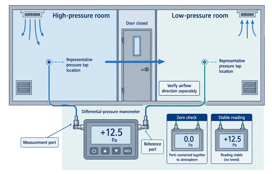
The protocol should identify:
- Defined boundary
- High- and low-pressure sides
- Reference location
- Measurement point or pressure taps
- Door and pass-through conditions
- Supply, return, exhaust, and local-exhaust states
- Operating mode
- Stabilization requirement
- Expected sign and magnitude
- Approved tolerance
- Alert and alarm thresholds where separately evaluated
- Required dynamic challenges
Pressure should be measured across each critical boundary rather than inferred from unrelated or remote room values. Measurement locations and reference paths should correspond with the approved airflow and pressure cascade.
Measurement Technique
The measurement process should include, as applicable:
- Confirm the intended high- and low-pressure sides.
- Confirm the reference instrument’s identification and calibration status.
- Inspect tubing and connections for leakage, obstruction, kinking, or reversal.
- Perform the required zero or reference check.
- Confirm the HVAC operating condition and stabilization.
- Position or connect the measurement points across the defined boundary.
- Allow the reading to stabilize.
- Record the magnitude and sign of the differential pressure.
- Compare the reference result with the installed indication where required.
- Repeat or trend readings when short-term variation can affect the conclusion.
No universal pressure-tap distance from a door, floor, ceiling, or wall applies to every installation. Locations should be representative of the defined boundary and consistent with the approved design and procedure.
Reference-Instrument Comparison
Where installed transmitters, gauges, or building-system displays provide GMP-relevant pressure data, reference readings should be compared with the installed indication. The comparison should account for:
- Pressure-tap location
- Tubing routing and condition
- Zero offset
- Engineering units
- Display resolution
- Damping or time delay
- Simultaneity of readings
- Reference-instrument uncertainty
A difference between two instruments is not automatically acceptable or unacceptable. Acceptance should consider the approved tolerance, measurement capability, and whether the difference could mask loss of the required pressure relationship.
Door and Operating Challenges
Closed-door pressure is a baseline condition. Where risk warrants, testing should also evaluate:
- Normal door opening and closing
- Door held open for a defined duration
- Airlock sequencing
- Pass-through operation
- Simultaneous adjacent-door conditions where credible
- Local-exhaust start or stop
- Process-equipment airflow demand
- Occupied and unoccupied modes
- Supply- or exhaust-fan disturbances
- Recovery after the disturbance ends
The acceptance basis may involve maintained directional airflow, limited reversal, alarm response, recovery time, or restrictions on simultaneous operations.
One criterion does not apply to every product-protection and containment arrangement.
Airflow-Direction and Visualization Studies
Airflow visualization makes air movement visible so that direction, interaction, turbulence, stagnation, entrainment, and recovery can be evaluated.
The study should be planned using the dedicated airflow visualization and smoke studies methodology.
Relevant conditions may include:
- At-rest baseline
- Representative equipment configuration
- Routine operator positions and movements
- Material transfer
- Door and pass-through operation
- Local-exhaust operation
- Interventions near exposed product or critical surfaces
- Startup, shutdown, or operating-mode transition
- Product-protection challenges
- Containment challenges
The selected tracer should be suitable for the environment. It should not contaminate the area, damage filters or equipment, or create an uncontrolled safety risk.
The record should preserve:
- Room and equipment configuration
- Operating state
- Camera position and field of view
- Tracer introduction point
- Activity sequence
- Time reference
- Observed airflow behavior
- Deviations
- Technical conclusion
Selected still images are insufficient when the conclusion depends on movement over time.
The evaluation should not be limited to a statement that smoke “flows in the correct direction.” It should address the actual protection or containment question at identified critical locations.
Nonviable-Particle Classification
Nonviable airborne-particle testing determines whether the cleanroom or clean zone meets its specified ISO classification under the defined occupancy state.
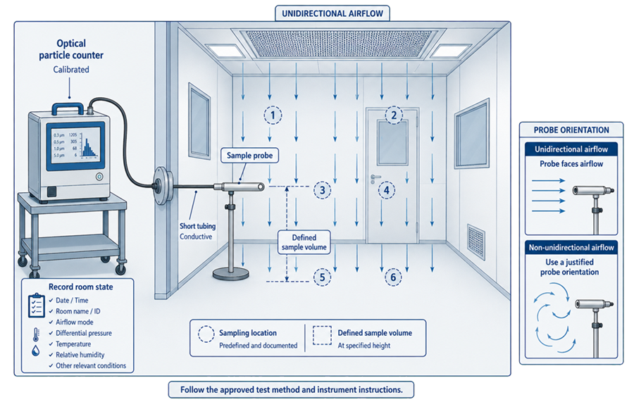
Classification should be performed using the applicable provisions of ISO 14644-1 and the approved protocol.
The sampling plan should define:
- Room or clean-zone boundary
- Applicable ISO class
- As-built, at-rest, or operational state
- Particle sizes evaluated
- Minimum number of sampling locations
- Location selection method
- Additional risk-based or process-specific locations
- Sample volume
- Sample duration
- Number of samples at each location
- Particle-counter flow rate
- Probe location and orientation
- Tubing material, length, and configuration
- Instrument identification and calibration status
- Required pre-use checks
- Room stabilization
- Personnel and activity conditions
- Acceptance calculation and decision rule
Sampling Technique
The sampling technique should control factors capable of altering the result.
These include:
- Probe position relative to the sampling location
- Probe orientation relative to the airflow
- Distance between the probe and intended sampling point
- Tubing length and internal diameter
- Tubing bends and restrictions
- Conductive tubing where appropriate
- Particle losses within the tubing
- Sample flow rate
- Coincidence limits
- Zero-count or background checks
- Instrument purge or stabilization
- Data storage and location identification
Probe orientation should reflect the airflow condition and approved method. No universal angular tolerance should be imposed unless it is established by the adopted procedure, instrument instructions, or applicable method.
Tubing should be kept as short and direct as practicable, particularly when larger particle sizes are evaluated. Excessive length, bends, vertical rise, incompatible tubing, or poor connections can produce particle losses that bias results low.
Classification Locations and Supplemental Locations
ISO 14644-1 establishes the classification sampling-location approach. Classification locations should not be replaced solely with locations selected through process risk assessment. Additional locations may be included based on:
- Exposed product
- Critical processing points
- Personnel activity
- Doors and material transfers
- Return-air locations
- Suspected low-airflow areas
- Prior adverse trends
- Equipment-generated particles
These additional locations should be identified as supplemental unless they form part of the classification plan under the applicable method.
Interpretation
A passing classification result demonstrates compliance with the specified airborne-particle concentration limit under the tested state and conditions. It does not independently establish:
- Acceptable viable environmental performance
- Suitable airflow protection of exposed product
- Acceptable recovery after a disturbance
- Appropriate pressure relationships
- Installed HEPA-filter integrity
- Continued control under every operational activity
- Suitability of the routine monitoring program
Those conclusions require the associated qualification and monitoring evidence.
Recovery Testing
Recovery testing determines the time required for a room or clean zone to return from a defined elevated particle concentration to a specified target after the challenge source is stopped. The protocol should define:
- Applicable room and cleanroom state
- Particle-size channel or channels
- Challenge material and method
- Challenge distribution
- Initial concentration or challenge endpoint
- Sampling location and rationale
- Particle-counter flow rate
- Sampling interval
- Test start and stop points
- Target concentration or recovery criterion
- Calculation or graphical evaluation method
- Maximum recovery time where specified
- Repetition requirements
- Treatment of anomalous results
Recovery performance depends on:
- Airflow quantity
- Air distribution
- Mixing behavior
- Filtration
- Room geometry
- Equipment
- Thermal effects
- Particle characteristics
- Sampling location
Recovery should not be predicted from ACH alone.
Functional HVAC recovery following a control disturbance is addressed in HVAC operational qualification. Particle-concentration recovery is a separate room-performance test even when both activities occur within the broader OQ phase.
Raw Data, Calculations, and Traceability
The final documentation should allow an independent reviewer to reproduce calculations and understand the actual test conditions. Raw data should include, as applicable:
- Individual readings before averaging
- Point, terminal, filter, room, and boundary identifiers
- Date and time
- Instrument used
- Engineering units
- Repeated or rejected readings with explanation
- Upstream and downstream aerosol results
- Filter-leak maps
- Pressure-boundary data
- Room dimensions and volume calculations
- Visualization video or file identifiers
- Particle-count data
- Recovery data and curves
- Environmental and operating conditions
- Operator attribution
Calculations should preserve:
- Formula
- Input values
- Units and conversions
- Correction factors
- Averaging method
- Rounding convention
- Result before final rounding where material
- Link to the source measurement
Transcribing only final averages or “pass” entries into a protocol weakens the evidence.
Original instrument files, printouts, photographs, videos, and electronic records should be retained or referenced under controlled record-management practices where they form part of the qualification result.
Measurement Uncertainty and Data Interpretation
Every measurement has uncertainty. The depth of the uncertainty evaluation should correspond to the method, proximity to the acceptance limit, and decision risk. Relevant contributors may include:
- Instrument calibration uncertainty or stated accuracy
- Resolution
- Repeatability
- Probe placement and alignment
- Flow-hood interaction with the terminal
- Turbulence and short-term variation
- Area and room-dimension measurements
- Correction factors
- Environmental conditions
- Operator technique
- Sampling statistics
- Particle losses in tubing
- Time synchronization
The protocol should define how results near an acceptance limit will be handled.
A marginal failure should not be rounded into a passing value. Instrument accuracy should not be mechanically added to or subtracted from every result without an approved decision rule.
Evaluation may use:
- Demonstrated test-method capability
- Instrument specifications
- Repeatability data
- Uncertainty estimates
- Guard bands where justified
- Predetermined decision rules
The selected approach should be documented before execution or during protocol approval rather than created after an unfavorable result.
Reported precision should reflect actual measurement capability. Excessive decimal places create false confidence.
Acceptance Criteria
Acceptance criteria should be approved before execution and should identify the source of each requirement. The acceptance basis may include:
- Approved user or system requirements
- Room data sheets
- Design calculations
- Contamination-control strategy
- Containment assessment
- Applicable regulations or guidance
- Adopted ISO or industry standards
- Filter and equipment specifications
- Process requirements
- Qualified operating ranges
- Alarm and operating procedures
- Risk assessment
Criteria should distinguish:
- Design target
- Balancing tolerance
- Qualification acceptance limit
- Alert or action level
- Alarm setpoint
- Instrument capability
- Retest requirement
A commonly used industry value may serve as a design reference or preliminary benchmark, but it becomes an acceptance criterion only when formally adopted and justified for the system.
Combined evidence should be evaluated. Individual tests can pass while the overall condition remains unacceptable.
Examples include:
- Acceptable room airflow with a failed terminal filter
- Correct closed-door pressure with unacceptable reversal during routine door use
- Acceptable average velocity with inadequate airflow at an exposed process location
- Passing classification with an unexplained localized filter leak
- Acceptable ACH with poor recovery performance
- Passing pressure magnitude with the incorrect airflow direction
Failures, Adjustments, Repairs, and Retesting
A failure or unexpected result should be documented when:
- An acceptance criterion is not met
- The approved method is not followed
- Required test conditions are not achieved or maintained
- An instrument is unsuitable, outside calibration, or incorrectly configured
- Raw data are missing or unreliable
- Results conflict with related evidence
- An unapproved adjustment or override affects the test
- Inaccessible areas prevent required coverage
- A repair, filter reseating, balancing adjustment, or control change occurs
The assessment should address:
- Affected room, filter, terminal, boundary, or test
- Requirement and actual result
- Immediate restriction or control
- Likely or confirmed cause
- Effect on previously completed tests
- Extent across similar locations
- Required correction
- Change-control or deviation requirements
- Retest scope
- Residual risk
- Final disposition
Retesting should occur after correction and restoration of the approved configuration. It should cover the failed item and any dependent results that could have been affected by the correction.
Examples include:
- Airflow rebalancing may require repeat room totals, ACH, pressure, visualization, classification, or recovery.
- Filter repair or replacement requires installed-system leakage retesting and may affect airflow, pressure, and downstream environmental evidence.
- Pressure-sensor correction may require repeat reference comparison, pressure verification, alarms, trends, and dynamic challenges.
- Particle-counter configuration errors may invalidate classification and recovery results.
- A changed method or instrument may require repeat testing if comparability cannot be established.
Repeated measurements should not be selectively averaged until a passing value appears. The initial failure, investigation, correction, rationale, and complete retest evidence must remain visible.
Documentation Package
The verification package should contain or reference:
- Approved protocol and revisions
- Scope and system boundaries
- Requirement and risk traceability
- Room, terminal, filter, and boundary maps
- Approved test conditions
- Instrument list and calibration evidence
- Test methods and instrument settings
- Raw data and original electronic files
- Calculations and independent checks
- Filter-leak maps and repair records
- Pressure-cascade results
- Visualization recordings and evaluations
- Particle-classification records
- Recovery data and curves
- Deviations and impact assessments
- Adjustments, corrections, and retest results
- Final as-left configuration
- Restrictions or deferred work
- Technical conclusion
- Required approvals
The report should state what was demonstrated and what was not.
A broad conclusion that “the HVAC system passed” is inadequate when the package covers only selected rooms, filters, operating modes, classifications, or test conditions.
Acceptance and Readiness for Environmental Qualification
The conclusion should confirm, as applicable:
- Required locations and operating conditions were tested
- Airflow quantities and velocities meet approved criteria
- Air-change calculations use measured data and controlled room volumes
- Supply, return, exhaust, and transfer relationships are reconciled
- Installed filter systems meet the adopted leakage criterion
- Required pressure relationships are established
- Dynamic door and operating conditions were evaluated where necessary
- Airflow visualization supports the protection or containment objective
- Nonviable-particle classification meets the specified ISO class
- Recovery performance meets the approved criterion where required
- Instruments and measurement capability were suitable
- Raw data and calculations are complete and traceable
- Failures, repairs, and retests are preserved and accepted
- Final configuration is identified
- Remaining limitations are defined
Successful verification establishes the measured room-performance baseline within the tested conditions.
It does not independently establish:
- Acceptable viable environmental performance
- Acceptable aseptic process simulation
- Long-term monitoring control
- Product protection during every intervention
- Containment during every process condition
- Continued performance after an unassessed change
Those conclusions require the applicable environmental performance qualification, monitoring, process, and lifecycle evidence.
Lifecycle Use and Requalification
Accepted verification results establish baselines for operation, monitoring, maintenance, calibration, change control, periodic review, investigation, and HVAC requalification. Reassessment may be required after:
- HEPA-filter repair or replacement
- Fan, drive, damper, terminal, or duct modification
- Airflow rebalancing
- Room-layout or equipment change
- Return, exhaust, or local-extraction change
- Pressure-setpoint or alarm change
- Sensor replacement or relocation
- Control-sequence or operating-mode change
- Door, pass-through, or airlock modification
- Room-use, classification, process, or containment change
- Repeated pressure, particle, recovery, or environmental excursions
- Extended shutdown
- Major maintenance
- Evidence that the original test condition no longer represents operation
Requalification scope should follow the affected attributes and dependencies.
Repeating one pressure reading after substantial airflow rebalancing is inadequate when the change can also affect airflow distribution, filter-face velocity, visualization, recovery, and classification.
Summary
Airflow, filtration, and pressure verification establishes measured evidence that an operating HVAC system produces the intended room and zone conditions.
A defensible program should:
- Define the verification boundary and test sequence
- Distinguish normative requirements from test methods and practical recommendations
- Apply current ISO 14644 terminology and applicable editions
- Establish prerequisites and representative test conditions
- Use calibrated and suitable instruments
- Measure and reconcile supply, return, exhaust, and transfer airflow
- Calculate ACH from traceable inputs without treating it as universal proof of performance
- Verify velocity at defined planes where required
- Test installed filter systems using an adopted method
- Verify pressure across defined boundaries and applicable dynamic conditions
- Use airflow visualization to evaluate actual product-protection or containment questions
- Perform nonviable-particle classification using the applicable ISO 14644-1 approach
- Define recovery challenges and endpoints
- Preserve raw data, calculations, uncertainty considerations, and original records
- Investigate failures and control repairs, adjustments, and retesting
- Evaluate combined evidence rather than isolated passing values
- Establish the baseline for environmental qualification and lifecycle requalification
The objective is not to collect a familiar set of readings or apply customary values to every room. It is to demonstrate, under defined and reproducible conditions, that the installed HVAC system provides the airflow, filtration, pressure behavior, particle control, and recovery performance required for its intended use.