

Material, Personnel, and Waste Flow Design
Purpose and Scope
Material, personnel, product, equipment, and waste flows determine how people and items move through a GMP facility without creating unacceptable contamination, cross-contamination, or mix-up risks.
Effective flow design considers more than separate arrows on a floor plan. It must account for:
- What is moving
- Where it originates and ends
- Its cleanliness or contamination status
- How it crosses controlled boundaries
- Whether it is exposed or enclosed
- What other movements occur at the same time
- Which physical, engineering, and procedural controls prevent adverse interaction
Complete physical separation is generally the most reliable solution when incompatible flows create significant risk. However, a crossing or shared route is not automatically unacceptable. Its suitability depends on the product, process, timing, frequency, room conditions, physical controls, cleaning, recovery, and procedural restrictions.
Flow design must therefore be evaluated as an integrated contamination-control system rather than as a collection of isolated pathways.
Regulatory Basis
21 CFR 211.42(b) requires adequate space for the orderly placement of equipment and materials to prevent mix-ups and contamination. It also requires the flow of components, drug-product containers, closures, labeling, in-process materials, and drug products through the building to be designed to prevent contamination.
21 CFR 211.42(c) requires operations to be performed within specifically defined areas of adequate size. Separate or defined areas—or other control systems—must be provided as necessary to prevent contamination or mix-ups during activities including:
- Receipt, identification, storage, and quarantine
- Holding of rejected materials
- Storage of released components and materials
- Storage of in-process materials
- Manufacturing and processing
- Packaging and labeling
- Quarantine before release
- Storage after release
- Laboratory operations
- Aseptic processing and related activities
The regulation establishes the required outcomes but does not prescribe one universal facility layout. Physical separation, defined areas, airlocks, controlled corridors, closed transfer systems, time separation, cleaning, access restrictions, and procedural controls may be used in combinations appropriate to the operation.
The selected controls must be supported by documented risk evaluation and remain effective during actual operating conditions, including simultaneous personnel, material, product, equipment, maintenance, and waste movements.
Establishing the Flow-Design Basis
Flow requirements should be defined from the intended process before the detailed room layout is finalized.
The design basis should identify:
- Products and processes performed in each area
- Aseptic, terminally sterilized, nonsterile, potent, sensitizing, hazardous, or otherwise controlled operations
- Exposed and closed processing steps
- Raw materials, components, intermediates, bulk product, and finished product
- Personnel categories and access requirements
- Mobile and permanently installed equipment
- Tools, change parts, cleaning equipment, and portable instruments
- Samples and laboratory transfers
- Rejected, returned, or quarantined materials
- Process waste, general refuse, and hazardous waste
- Required cleanliness transitions
- Product-protection and containment requirements
- Maximum staffing and throughput
- Normal, peak, maintenance, cleaning, and emergency conditions
These needs should be translated into the User Requirements Specification early enough to influence room adjacencies, corridors, airlocks, door sizes, staging space, decontamination provisions, and maintenance access.
Personnel Flow
Personnel are a major source of particles and microbiological contamination. Their movement should be controlled according to the environment entered, the activity performed, and the product or process risk.
Personnel-flow design should address:
- Normal entry and exit routes
- Gowning and degowning sequences
- Handwashing or sanitization steps
- Separation of incoming and outgoing personnel where required
- Access authorization
- Maximum airlock occupancy
- Movement between different cleanliness or containment zones
- Movement between incompatible product or process areas
- Supervisory, quality, laboratory, and visitor access
- Maintenance and contractor entry
- Emergency egress
- Removal of contaminated garments or protective equipment
The progression should be understandable and supported by room arrangement, visual boundaries, access controls, and operating procedures.
Backtracking should be minimized, particularly where it would return personnel from a higher-risk activity into a cleaner or protected area. Where the same route is used for entry and exit, the design should define how separation is maintained through timing, gowning controls, cleaning, airlock recovery, or other justified measures.
Emergency egress must remain available. Emergency routes do not need to duplicate normal GMP movement controls, but procedures should address product disposition, area recovery, and restoration after their use.
Incoming Material and Component Flow
Incoming materials may carry dust, fibers, microorganisms, shipping residue, damaged packaging, or contamination from warehouses and transportation.
The design should establish a controlled progression from receipt to manufacturing use, including:
- Receipt and identification
- Quarantine pending sampling, testing, or release
- Separation of released and rejected materials
- Removal of shipping materials where appropriate
- Inspection of containers and packaging
- Cleaning, sanitization, or decontamination before transfer
- Staging at controlled boundaries
- Transfer through material airlocks, pass-throughs, or other systems
- Protection after cleaning or decontamination
- Prevention of confusion between cleaned and uncleaned items
- Status identification throughout movement
The required treatment depends on the material, packaging configuration, receiving environment, destination, and process risk. Not every incoming container requires the same decontamination method.
The design should identify where outer packaging is removed and where wiping, washing, spraying, irradiation, vapor-phase treatment, or another decontamination method is performed. Space, drainage, exhaust, contact time, drying, and segregation requirements must be considered where such treatments are used.
A decontaminated item should not be moved through an uncontrolled route that can negate the treatment before it reaches its destination.
Material Airlocks and Transfer Points
Material airlocks protect transitions between areas with different cleanliness, pressure, containment, or access requirements.
Their design should consider:
- Materials and containers being transferred
- Cart and pallet dimensions
- Required staging capacity
- Maximum transfer load
- Door swing and usable clearance
- Cleaning and decontamination activities
- Pressure stabilization and environmental recovery
- Direction of transfer
- Separation of incoming and outgoing items
- Status indication
- Access control
- Door alarms and interlocks
- Emergency release
- Communication between sending and receiving personnel
An airlock should not be treated as general storage. Uncontrolled accumulation can prevent cleaning, obstruct airflow, confuse material status, and interfere with door operation.
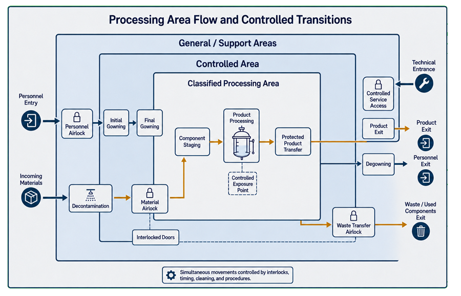
Where door interlocks are used, they should prevent simultaneous opening under defined normal conditions. The interlock strategy must also address power failure, emergency release, alarm response, maintenance bypass, and restoration to normal operation.
Not every airlock requires an automated interlock. Procedural door control may be adequate for some lower-risk applications, but the decision should be justified according to the pressure relationship, contamination risk, transfer frequency, occupancy, and consequences of simultaneous door opening.
Product and In-Process Material Flow
Product flow should be evaluated separately from general material flow because the product’s exposure and status change throughout manufacturing.
The assessment should identify:
- Where product is first exposed
- Open and closed processing steps
- Transfers between equipment
- In-process hold locations
- Sampling points
- Movement between classified or controlled areas
- Movement between different processing stages
- Clean and dirty equipment interfaces
- Rework or recirculation pathways
- Rejected or nonconforming product movement
- Movement to filling, packaging, storage, or shipment
- Maximum allowable transfer and hold times
Where possible, product should move through closed equipment, piping, contained transfer systems, or protected containers. Closed movement can reduce dependence on room classification and personnel controls, but the closure and transfer connections must be suitable for the intended process.
The layout should prevent confusion between materials or products with different identities, strengths, batch statuses, or processing stages. Physical separation, defined staging positions, labeling, electronic status controls, line clearance, and procedural controls may all contribute to preventing mix-ups.
Flow design must also address reverse or exceptional movement, such as returning material for reprocessing, investigation, reconciliation, or disposal.
Equipment, Tools, and Component Movement
Equipment movement is frequently omitted from early facility-flow studies even though it can be more disruptive than routine material transfer.
The design should evaluate movement of:
- Mobile manufacturing equipment
- Product-contact assemblies
- Change parts and format parts
- Portable tanks and transfer vessels
- Carts and racks
- Cleaning equipment
- Calibration standards and instruments
- Maintenance tools
- Replacement motors, pumps, filters, and other components
- Removed or failed equipment
- New equipment introduced after facility release
The route should provide adequate:
- Door and corridor width
- Turning clearance
- Floor loading capacity
- Vertical clearance
- Lifting and rigging access
- Protection of walls, doors, and cleanroom surfaces
- Separation from exposed product
- Cleaning or decontamination capability
- Staging before and after transfer
The design must address how large equipment will be installed, removed, and replaced. A room may support routine operation but remain poorly designed if equipment replacement requires demolition of cleanroom boundaries or uncontrolled passage through critical manufacturing areas.
Clean and dirty equipment pathways should be defined where reusable equipment or components move to and from washing, sterilization, maintenance, or storage areas.
Maintenance Access and Technical Support Flow
Maintenance activities introduce personnel, tools, parts, lubricants, debris, and open equipment conditions that differ from routine production.
Where practical, serviceable components should be accessible from technical or unclassified spaces. Examples include:
- Motors and drives
- Control panels
- Utility valves
- Filters
- Dampers
- Sensors and transmitters
- Lighting components
- Ceiling-mounted equipment
- Utility connections
External service access reduces entry into classified areas and limits disruption to cleaning, environmental control, and production.
Where maintenance must occur inside a controlled area, the design and procedures should address:
- Personnel entry and gowning
- Tool and replacement-part introduction
- Protection or removal of exposed product and materials
- Equipment isolation
- Control of debris, lubricants, and residues
- Removal of failed components
- Cleaning and disinfection
- Environmental recovery
- Inspection or testing before release
- Required qualification or verification
Maintenance flow should be shown in design evaluations rather than assumed to be an infrequent exception.
Waste and Rejected-Material Flow
Waste may include used garments, disposable supplies, packaging, cleaning materials, process residues, broken containers, rejected product, microbiological waste, hazardous material, and removed equipment components.
Waste-flow design should address:
- Collection at the point of generation
- Suitable closed or covered containers
- Identification and segregation
- Maximum holding time
- Staging locations
- Removal frequency
- Transfer through airlocks or controlled exits
- Decontamination where required
- Prevention of leakage or dispersal
- Movement to final holding or disposal
- Cleaning of reusable waste containers and carts
Waste should normally progress away from protected operations toward less-controlled areas. However, some facilities cannot provide a completely dedicated waste corridor or exit.
When waste and incoming materials use a shared route or airlock, the control strategy should evaluate:
- Whether movements can occur simultaneously
- Required time separation
- Cleaning between movements
- Closed-container integrity
- Airlock recovery
- Directional restrictions
- Material status controls
- Frequency and volume
- Consequences of a spill or container failure
A shared route may be acceptable when the risks are understood and effectively controlled. A procedure that merely states “do not cross flows” without defining timing, cleaning, responsibilities, and recovery conditions is not sufficient.
Crossing and Shared Flows
Crossing paths should trigger evaluation, not automatic rejection.
A crossing may present limited risk when:
- Items remain enclosed and protected
- Movements occur at different times
- The area is cleaned between incompatible movements
- Airlock recovery is demonstrated
- Direction and sequence are controlled
- The crossing is infrequent
- Personnel occupancy is limited
- Material identity and status remain clear
- The consequence of interaction is low
The same crossing may be unacceptable when:
- Sterile or exposed product is present
- Open clean components cross waste or used equipment
- Containment and product-protection requirements conflict
- Simultaneous movement cannot be prevented
- Cleaning cannot be performed effectively
- Traffic disrupts critical airflow
- Congestion creates mix-up or handling risk
- The crossing occurs routinely at high volume
- Procedures cannot be followed reliably under actual operating conditions
Physical and engineering controls are generally more reliable than administrative controls. However, physical separation is not the only possible acceptable control. The complete arrangement should be judged according to risk, practicality, and demonstrated effectiveness.
Simultaneous Movement Restrictions
Flow diagrams often show individual routes but fail to identify which movements may occur at the same time.
The operating strategy should define incompatible simultaneous activities, such as:
- Personnel entry while waste is being removed
- Incoming clean components while used equipment exits
- Opening both airlock doors
- Moving materials while exposed product is present
- Maintenance access during aseptic or open processing
- Gowning and degowning in the same space
- Transfer between incompatible product campaigns
- Cleaning while released materials are staged nearby
Restrictions may be implemented through:
- Physical separation
- Door interlocks
- Access-control logic
- Traffic signals or status indicators
- Batch or room-status controls
- Scheduling
- Written procedures
- Supervisory authorization
- Electronic workflow controls
The selected controls should define responsibility, sequence, waiting time, cleaning, airlock recovery, and response to abnormal conditions.
Integration with Zoning, Classification, and Pressure
Flow design must remain consistent with facility zoning and segregation.
Movement across a boundary may affect:
- Cleanroom classification
- Pressure relationships
- Containment
- Environmental recovery
- Personnel gowning
- Material cleanliness
- Cleaning requirements
- Access authorization
The required direction of pressure depends on the protection objective. Positive pressure may support product protection, while negative pressure may support containment. Where these objectives conflict, the design may require pressure sinks, pressure bubbles, dedicated airlocks, closed transfers, barrier systems, or separate routes.
Door use and material movement should be considered when establishing airflow and pressure relationships. A pressure cascade demonstrated with closed doors may not remain stable during frequent or simultaneous transfers.
Cleanroom classification does not by itself determine acceptable flow arrangements. The process, exposure condition, product risk, containment needs, and operating controls must be evaluated together.
Evaluating Flow Using Drawings and Diagrams
Flow design should be evaluated using controlled layout drawings or flow diagrams based on the intended operating configuration.
Useful drawings may include:
- Architectural floor plans
- Room and corridor layouts
- Cleanliness and containment zoning drawings
- Personnel-flow diagrams
- Incoming-material and component-flow diagrams
- Product and in-process material-flow diagrams
- Equipment and tool-movement diagrams
- Waste and rejected-material-flow diagrams
- Maintenance-access diagrams
- Emergency-egress routes
- Pressure-cascade drawings
- Airlock and pass-through details
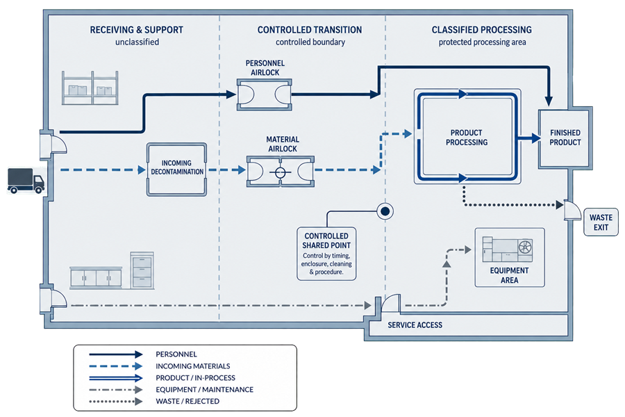
Distinct colors or line styles should identify each flow. Directional arrows, origin and destination, cleanliness status, transfer method, airlock use, and staging points should be clearly shown.
Overlaying multiple flows on the same layout helps identify:
- Crossings
- Shared corridors
- Shared airlocks
- Congestion points
- Reverse movement
- Uncontrolled transitions
- Inadequate staging
- Conflicts between product protection and containment
- Activities that must not occur simultaneously
Drawings should reflect the installed equipment and actual operating arrangement. A route that appears adequate on an empty architectural plan may become impractical after equipment, carts, staging racks, and personnel positions are included.
Normal, Peak, and Abnormal Conditions
The facility should be evaluated under more than one operating scenario.
Flow studies should include:
- Normal production
- Maximum anticipated staffing
- Peak material throughput
- Shift changes
- Batch changeover
- Cleaning and disinfection
- Equipment setup and removal
- Preventive and corrective maintenance
- Calibration
- Waste accumulation and removal
- Rejected-material movement
- Spill or container failure
- Airlock or door-interlock failure
- HVAC setback or recovery
- Emergency evacuation
- Introduction or removal of major equipment
Controls that function only during low activity do not establish a robust flow strategy. Congestion, waiting, temporary staging, and workarounds observed during peak activity are evidence that the design basis may be incomplete.
Design Review and Qualification
Flow requirements should be reviewed by representatives from:
- Manufacturing
- Engineering
- Quality assurance
- Validation
- Facilities
- Maintenance
- Cleaning and sanitation
- Environmental monitoring
- Warehousing and material control
- Microbiology
- Safety
- Security or access control
The review should document identified conflicts, risk controls, assumptions, unresolved decisions, and required design changes.
Facility Design Qualification should confirm that the proposed layout supports intended flows before construction makes changes difficult or expensive. Review evidence may include approved layouts, flow overlays, room-data sheets, airlock specifications, interlock descriptions, risk assessments, and design-review records.
Commissioning and qualification should verify relevant installed and functional features, including:
- Room and door arrangement
- Airlock size and configuration
- Door alarms and interlocks
- Access controls
- Pressure relationships
- Transfer equipment
- Pass-through operation
- Required status indications
- Cleaning and decontamination provisions
- Recovery after door operation
- Space and clearances for defined movements
Operational verification may include representative or worst-case transfer scenarios rather than relying only on static inspection.
Operational Control and Lifecycle Management
Approved flow diagrams should match actual practices and remain available to support training, investigations, audits, and change assessment.
Routine oversight should consider:
- Deviations involving incorrect movement
- Congestion or temporary staging
- Door-interlock bypasses
- Airlock alarms
- Repeated pressure disturbances
- Cleaning failures
- Product or material mix-ups
- Environmental-monitoring trends
- Maintenance difficulties
- Operator workarounds
- Changes in staffing or throughput
Relevant operating conditions may also affect environmental monitoring program design, particularly where movement, door use, interventions, or staging influence contamination risk.
Changes to room use, equipment layout, corridors, doors, airlocks, transfer methods, product type, batch size, staffing, cleaning methods, or material volume require documented change-impact assessment.
The assessment should determine whether drawings, risk evaluations, procedures, training, commissioning, qualification, monitoring locations, or contamination controls must be revised.
Common Flow-Design Weaknesses
Common weaknesses include:
- Flow diagrams that omit product or equipment movement
- Drawings that do not reflect the installed layout
- Failure to show maintenance and cleaning activities
- Airlocks too small for the intended carts or transfers
- Uncontrolled airlock storage
- No defined incoming-material decontamination point
- Clean and dirty equipment using the same route without controls
- Simultaneous opening of airlock doors
- Incompatible simultaneous movements
- Uncontrolled waste staging
- Routes that require routine backtracking
- Product or material status becoming unclear during staging
- Failure to evaluate peak staffing and throughput
- Large equipment with no practical replacement route
- Absolute reliance on procedures without considering physical improvements
- Automatic rejection of every crossing without evaluating actual risk
- Qualification performed without representative movement scenarios
- Changes implemented without updating flow drawings
These conditions should be evaluated according to their actual effect on contamination, cross-contamination, containment, product identity, and operational control.
Summary
Material, personnel, product, equipment, maintenance, and waste flows must function as one coordinated facility-control system.
The preferred design eliminates unnecessary crossings, provides suitable separation, controls transitions, and supports clear progression through the facility. Where dedicated routes are not practical, shared or crossing flows require documented evaluation of timing, enclosure, cleaning, airlock operation, recovery, simultaneous movement, and procedural controls.
Flow design should be developed from process requirements, evaluated using layout drawings and overlaid flow diagrams, verified under representative operating conditions, and maintained through change control. The objective is not to create perfectly separate arrows on paper. It is to prevent contamination, cross-contamination, and mix-ups during actual facility operation.