

Airflow Visualization – Smoke Studies
Airflow visualization is a qualitative study used to demonstrate how air moves through a cleanroom, controlled area, clean zone, or aseptic processing environment. It provides visible evidence of airflow direction, distribution, interaction with equipment and personnel, and protection of critical locations.
The term smoke study is commonly used for all airflow visualization work, but two applications should be distinguished:
- Cleanroom airflow visualization evaluates room-scale airflow distribution, movement toward returns or exhausts, localized turbulence, stagnation, and airflow across doors or transfer openings.
- Aseptic-process smoke studies evaluate first-air protection and airflow behavior around exposed sterile product, components, critical surfaces, equipment, and defined operator interventions.
Both study types require an approved protocol, justified visible medium, representative operating conditions, effective video recording, predetermined acceptance criteria, and documented conclusions. Their objectives and level of control, however, are not identical.
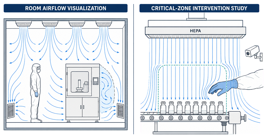
Caption: Cleanroom airflow visualization evaluates room-scale air distribution and return paths, while an aseptic-process smoke study demonstrates critical-zone protection during representative interventions.
Study Objectives
The study objectives must be defined before selecting the smoke source, release locations, operating conditions, or camera positions.
Cleanroom Airflow Visualization
Room-level studies may be designed to evaluate:
- Air movement from supply diffusers toward returns or exhaust grilles
- Distribution around walls, equipment, partitions, and other obstructions
- Directional airflow across doors, pass-throughs, airlocks, and transfer openings
- Localized recirculation, turbulence, stagnation, or short-circuiting
- Effects of equipment heat loads or moving components
- Influence of personnel movement and door operation
- Capture or containment performance in dispensing or dust-control areas
- Conditions associated with environmental-monitoring excursions or investigations
These studies supplement measured air volume, air velocity, pressure differential, recovery, and particle data. They do not replace quantitative HVAC testing.
Aseptic-Process Smoke Studies
Aseptic studies focus on whether airflow protects exposed sterile product and critical surfaces during actual or simulated processing. Typical objectives include demonstrating:
- Unidirectional airflow within the defined critical zone
- First-air protection of open containers, closures, product pathways, and critical surfaces
- Absence of airflow movement from personnel or less-clean locations toward exposed sterile materials
- Acceptable airflow behavior during routine and nonroutine interventions
- Continued protection during line setup, replenishment, stoppages, adjustments, sampling, and component transfers
- Airflow stability around doors, glove ports, mouse holes, conveyors, and equipment interfaces
- Adequate protection under the most challenging justified operating configuration
The study must evaluate the actual airflow path between the HEPA-filtered supply and the protected critical location. Average room conditions alone do not demonstrate first-air protection.
Regulatory and Technical Basis
The U.S. regulations do not prescribe a test called a smoke study. They require appropriate facility design, HEPA-filtered air for aseptic processing, adequate ventilation, and controls over air pressure, microorganisms, dust, humidity, and temperature. These requirements are established principally through 21 CFR 211.42 and 21 CFR 211.46.
The FDA Guidance for Industry: Sterile Drug Products Produced by Aseptic Processing explains the expectation that airflow patterns in critical areas be evaluated and that studies be conducted under dynamic conditions representing actual operations.
ISO 14644-3 provides test methods for airflow-direction and airflow-visualization studies in cleanrooms and clean zones. The applicable method and acceptance criteria must still be selected according to the facility, process, contamination-control objective, and governing regulatory framework.
Study Design and Protocol Development
The protocol should establish what is being demonstrated and how the resulting visual evidence will be interpreted. At minimum, it should define:
- Study scope and boundaries
- Room, zone, line, hood, RABS, or isolator being evaluated
- Specific airflow characteristics to be demonstrated
- Equipment configuration and HVAC operating state
- At-rest or operational condition
- Number and activity of personnel
- Smoke-generation equipment and visible medium
- Smoke-release locations and release technique
- Routine and nonroutine interventions to be performed
- Doors, transfer ports, conveyors, and equipment movements to be challenged
- Camera positions and recording requirements
- Predetermined acceptance criteria
- Required cleaning or recovery following the study
- Deviation handling and reporting requirements
Diagrams, photographs, or marked-up layouts should identify smoke-release points, critical locations, return or exhaust paths, operator positions, intervention locations, and camera views.
Selection of the Visible Medium
The visible medium must make the airflow path observable without creating an unacceptable contamination, residue, equipment, fire, oxygen-deficiency, or personnel-safety risk.
Potential methods include:
- Water-based fog
- Glycol- or glycerin-based aerosol
- Cryogenic fog generated using liquid nitrogen
- Carbon-dioxide fog generated using dry ice
- Other qualified tracer or visualization methods
No medium is universally preferable. Selection should consider:
- Visibility and persistence
- Buoyancy relative to the airflow being evaluated
- Droplet or particle behavior
- Residue on equipment, HEPA filters, sensors, or product-contact surfaces
- Compatibility with the room and process
- Required post-study cleaning and disinfection
- Potential effect on environmental-monitoring instruments
- Oxygen-displacement, carbon-dioxide, cryogenic, electrical, and slip hazards
- Manufacturer operating instructions
- Ability to produce a controlled and repeatable release
A documented safety assessment should address personnel exposure, ventilation, oxygen or carbon-dioxide monitoring where applicable, cryogenic handling, emergency response, and restrictions on room occupancy.
The selected medium should be generated and positioned so that the study represents airflow behavior rather than momentum imparted by the fog generator. Excessive discharge velocity can create an artificial airflow pattern and invalidate the observation.
Operating Conditions and Worst-Case Challenges
Study conditions must correspond to the intended objective.
Room airflow visualization may be performed at rest, operationally, or under both states. Operational studies should include the normal equipment configuration, representative personnel occupancy, material staging, door operation, and other activities capable of influencing airflow.
Aseptic-process studies should normally represent dynamic operations and include justified worst-case conditions, such as:
- Maximum permitted personnel occupancy
- Largest or most obstructive equipment configuration
- Maximum line speed where speed affects airflow
- Extended or complex interventions
- Interventions closest to exposed sterile product
- Simultaneous activities permitted by procedure
- Component replenishment
- Line stoppage and restart
- Removal of fallen or jammed components
- Door, glove-port, or transfer-port operation
- Movement of carts, trays, tools, or equipment
- Aseptic connections and disconnections
- Sampling and environmental-monitoring activities
The interventions evaluated should be traceable to approved operating procedures, intervention lists, risk assessments, and aseptic process simulations. A visually convenient demonstration that omits challenging operations does not represent the process.
Smoke Release and Camera Positioning
Smoke should be introduced at locations that allow the complete airflow path to be evaluated. Releasing fog only beneath the HEPA filter may demonstrate downward movement but fail to show what occurs around equipment, interventions, and exposed product.
Release points may include:
- Beneath HEPA-filter faces
- Upstream and downstream of equipment obstructions
- Around exposed containers or components
- Near operator access points
- At door gaps and transfer openings
- Around returns or exhaust grilles
- At glove ports and barrier interfaces
- Near suspected recirculation or stagnation zones
The release method must not contact exposed sterile product or critical surfaces unless specifically justified and controlled.
Camera positions should be established during study planning. The recording must show both the visible airflow and the relevant process relationship. A close view of smoke without the product, intervention, or equipment reference point may be impossible to interpret.
Multiple synchronized views may be necessary for complex filling lines, isolators, RABS, or enclosed equipment. Fixed cameras are generally preferable because they provide stable, repeatable views, but handheld recording may be used when justified and controlled.
Each recorded sequence should identify:
- Study location
- Camera view
- Operating condition
- Intervention or activity
- Smoke-release location
- Direction of intended airflow
- Date or study identifier
Acceptance Criteria and Interpretation
Acceptance criteria must be linked to the study objective rather than limited to a general requirement that airflow “looks acceptable.”
Room-Level Acceptance Criteria
Depending on the intended control strategy, acceptable room airflow may require demonstration that:
- Air moves in the intended general direction
- Supply air reaches occupied or controlled portions of the room
- Airflow progresses toward the intended returns or exhausts
- Doors and transfer openings do not cause unacceptable reversal
- No significant unexplained stagnation or recirculation affects critical locations
- Contaminants are directed toward the intended capture or exhaust path
- Equipment and personnel do not compromise the defined airflow strategy
Non-unidirectional airflow may include mixing and localized recirculation. Such behavior is not automatically unacceptable unless it conflicts with the intended contamination-control or containment function.
Aseptic-Process Acceptance Criteria
An aseptic-process smoke study should demonstrate that:
- Airflow is unidirectional where required by the critical-zone design
- First air reaches exposed sterile product and critical surfaces
- Air does not move from personnel, equipment, or less-clean areas toward exposed sterile materials
- Interventions do not create unacceptable turbulence, reflux, entrainment, or airflow obstruction
- Critical-zone protection remains effective throughout the intervention
- Doors, ports, conveyors, and equipment movements do not compromise the protected zone
- Observed airflow is consistent with the established process and contamination-control strategy
Momentary bending of airflow around an object is not necessarily a failure. The determining issue is whether the disturbance redirects contamination toward an exposed critical location or prevents adequate first-air protection.
Conclusions should be based on review of the complete video sequence, not selected still images.
Representative Airflow Visualization Examples
The following examples illustrate representative smoke-delivery methods and airflow behaviors that may be observed during airflow visualization studies. Each observation must be interpreted against the study objective, equipment configuration, critical locations, operating condition, and predetermined acceptance criteria.
Smoke Manifold
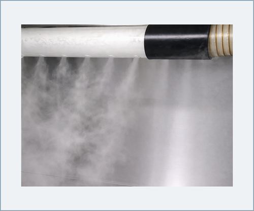
A perforated smoke manifold can distribute the visible medium across a broad airflow face. When properly designed and positioned, it supports evaluation of airflow uniformity and helps identify localized disturbances across the evaluated area.
The manifold release should be sufficiently uniform to make differences in airflow behavior observable. Its discharge velocity must be controlled so the smoke-generation method does not create, redirect, or suppress the airflow pattern being evaluated.
Unidirectional Airflow
Smoke streams move in substantially parallel paths toward the intended downstream location without upward reflux, excessive lateral movement, or movement from less-clean locations toward the protected zone.
Smoke streams move in substantially parallel paths toward the intended downstream location without upward reflux, excessive lateral movement, or movement from less-clean locations toward the protected zone.
Local Protection Zone
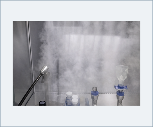
Airflow visualization may demonstrate protection of a defined local protection zone within a hood or other controlled enclosure. The protected zone may be limited to an open container, product pathway, critical surface, or specific processing location.
Acceptance depends on maintaining the intended airflow around the defined critical location. The entire enclosure does not necessarily need to exhibit identical airflow behavior when the system is designed to provide localized rather than enclosure-wide protection. The study should clearly identify:
- The boundaries of the protected zone
- The critical location requiring protection
- The intended airflow direction
- The surrounding equipment configuration
- Activities or interventions capable of disturbing the zone
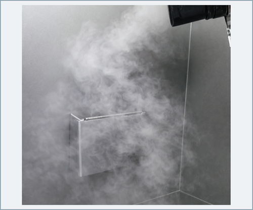
Localized Turbulence or Reflux
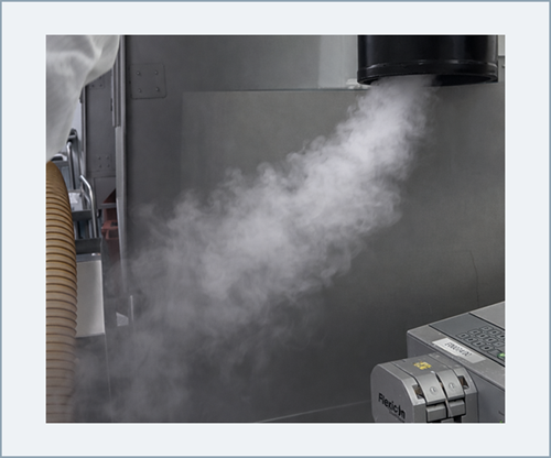
Lateral movement, swirling, upward reflux, entrainment, or recirculation indicates a localized airflow disturbance. The observation should be evaluated for its location, duration, frequency, cause, and relationship to nearby critical locations.
Localized turbulence is not automatically unacceptable in a non-unidirectional cleanroom. It becomes unacceptable when it conflicts with the established contamination-control or containment strategy. Within an ISO 5 aseptic critical zone, turbulence or reflux is unacceptable when it:
- Interrupts first-air protection
- Carries air from personnel or less-clean locations toward exposed sterile materials
- Creates persistent recirculation around an exposed critical surface
- Entrains contamination into the protected airflow path
- Results from an intervention or equipment configuration that will occur during routine processing
An unacceptable or inconclusive observation requires documented investigation, appropriate correction, and repetition of the affected study sequence under representative conditions.
Video Records and Data Integrity
The original video is raw qualification data and should be retained in its original format. Editing may be used to create annotated review copies, but it must not replace or obscure the source recording.
The record set should include:
- Original unedited video files
- File identifiers linked to protocol steps
- Camera and view identification
- Date and time information
- Annotated copies where used
- Study observations
- Deviations and investigations
- Reviewer comments and approvals
- Final conclusions
- Cleaning and room-release records where applicable
Video compression, conversion, clipping, or annotation should be controlled. The retained evidence must allow an independent reviewer or inspector to understand what occurred before, during, and after each evaluated intervention.
Deviations and Unacceptable Observations
Unexpected turbulence, backflow, stagnation, loss of first-air protection, inadequate video coverage, incorrect process configuration, or failure to perform a required intervention should be documented and assessed.
The investigation should determine whether the observation resulted from:
- HVAC or airflow-distribution performance
- Equipment configuration
- Operator technique
- Intervention design
- Smoke-release technique
- Camera placement
- An unrepresentative study condition
- Inadequate study instructions
Corrective action may include equipment modification, airflow balancing, procedural changes, intervention redesign, operator retraining, additional camera coverage, or repetition of affected study sequences. Failed or ambiguous sequences should not be resolved solely through narrative justification when additional visual evidence is needed.
Lifecycle Use and Re-Study Triggers
Airflow visualization is not limited to initial qualification. Previous studies should be evaluated during change control, investigation, periodic review, and HVAC requalification.
Re-study may be required following:
- Modification of HEPA filters, diffusers, returns, or exhausts
- Airflow balancing or significant setpoint changes
- Changes to room pressure relationships
- Installation, relocation, or removal of equipment
- Filling-line or barrier-system modification
- Changes to critical interventions or operating procedures
- Increased personnel occupancy
- Changes to line speed, container format, or component presentation
- Repeated environmental-monitoring excursions
- Identification of an airflow-related contamination risk
- Major maintenance, shutdown, or facility renovation
- Unexplained changes in airflow, pressure, or recovery performance
The extent of re-study should be based on documented impact assessment. A localized change may justify targeted testing, while a change affecting the overall airflow strategy may require comprehensive repetition.
Relationship to Qualification and Contamination Control
Airflow visualization should be evaluated with related qualification and monitoring evidence, including:
- HEPA-filter integrity testing
- Air velocity and air-volume measurements
- Room pressure-differential verification
- Air-change and recovery testing
- Cleanroom classification
- Environmental-monitoring data
- Aseptic process simulation results
- Intervention risk assessments
- HVAC alarm and trend review
A smoke study demonstrates visible airflow behavior under defined conditions. It does not independently establish cleanroom classification, microbiological control, containment performance, or aseptic-process capability