

Aseptic Filling Line Architecture
Aseptic filling-line architecture defines how sterile product, sterile containers, closures, filling equipment, environmental protection, automation, and material-transfer systems are integrated to produce a filled and closed container without compromising sterility.
The architecture extends beyond the filling machine itself. It includes the controlled pathways through which product and components enter the line, the locations where sterile materials are exposed, the barrier or critical-zone protection, the mechanisms used for filling and initial closure, and the interfaces with upstream and downstream equipment.
The architectural objective is to provide a system that:
- Maintains appropriate protection wherever sterile product, containers, closures, or critical surfaces are exposed
- Minimizes manual aseptic manipulations
- Supports cleaning, sterilization, and bio-decontamination
- Prevents mechanical and microbiological contamination
- Provides reproducible filling and closure performance
- Detects and rejects nonconforming units
- Enters a defined safe state following equipment or utility failures
- Produces complete and reviewable manufacturing records
- Can be qualified and maintained throughout its lifecycle
The exact configuration depends on the product, container format, filling technology, barrier system, production scale, and whether the product is filled as a liquid or transferred to a lyophilizer in partially stoppered containers.
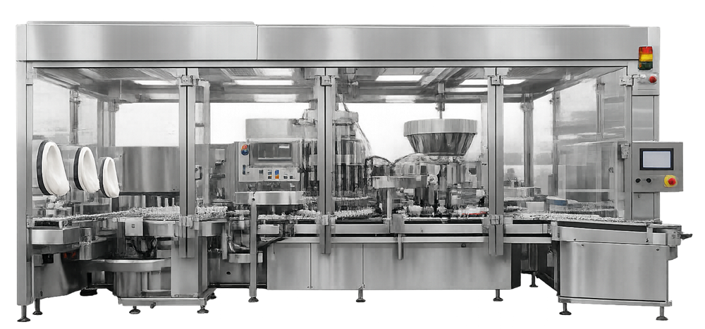
Architectural boundary
The filling-line boundary should be defined during requirements development and design qualification. The boundary normally includes more than the visible filling machine.
Depending on the process, it may include:
- Container infeed and transfer from a depyrogenation tunnel
- Tub or nest opening and container introduction
- Sterile stopper and closure transfer
- Product vessels or product connection points
- Sterilizing-grade filtration assemblies
- Product tubing, manifolds, pumps, and filling needles
- Container transport and indexing systems
- Filling and in-process control stations
- Stoppering or initial sealing
- Capping or crimping
- Reject and reconciliation systems
- Barrier enclosure and glove systems
- Localized HEPA-filtered airflow
- Environmental-monitoring provisions
- Lyophilizer loading and unloading interfaces
- Outfeed to inspection and packaging
- Automation, recipes, alarms, and electronic records
- Supporting utilities
The validation boundary should identify which functions belong to the filling line and which are qualified under connected systems. For example, the depyrogenation tunnel, isolator, RABS, lyophilizer, product-filtration skid, and computerized control platform may have separate qualification packages while remaining critical interfaces to the filling process.
Integrated line configuration
A conventional vial-filling line may include the following sequence:
- Sterilized-container introduction
- Container accumulation and spacing
- Container detection and positioning
- Filling
- In-process fill verification
- Stopper feeding and placement
- Stopper-height verification
- Capping or crimping
- Closure inspection
- Rejection and reconciliation
- Transfer to downstream inspection
The actual sequence can differ. For example:
- Capping may be physically separated from the filling and stoppering zone.
- Partially stoppered vials may be transferred to a lyophilizer before final stoppering and capping.
- Nested syringes or cartridges may enter in presterilized tubs and nests.
- Single-use product pathways may replace reusable vessels, manifolds, and pumps.
- Robotic systems may perform container transfer, filling, stoppering, or lyophilizer loading.
- In-process weight checks may occur before filling, after filling, or at defined sampling intervals.
The configuration should be evaluated as an integrated process. Container spacing, pump actuation, needle movement, stopper placement, inspection, rejection, and barrier operation are interdependent.
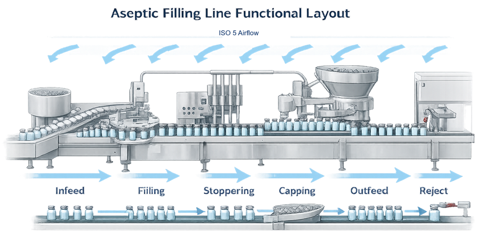
Conceptual aseptic filling-line layout showing container infeed, filling, stoppering, capping, outfeed, rejection, and protective airflow
Container and presentation formats
Filling-line architecture is influenced by the container format and the condition in which the container enters the machine.
Common presentations include:
- Glass or polymer vials
- Ampoules
- Prefilled syringes
- Cartridges
- Bottles
- Bags or flexible containers
Bulk containers
Bulk vials or similar containers may be washed and depyrogenated before passing directly from a depyrogenation tunnel into the critical filling zone. Architectural considerations include:
- Tunnel-to-filling-line interface
- Container cooling
- Protection of depyrogenated containers
- Accumulation control
- Glass-to-glass contact
- Container tipping
- Particle generation
- Line-clearance access
Nested or ready-to-use containers
Ready-to-use syringes, cartridges, or vials may arrive sterilized in tubs, trays, or nests. Their introduction can require:
- Outer-bag removal
- Surface decontamination
- Tub opening
- Liner or lid removal
- Nest transfer
- Robotic handling
- Controlled waste removal
The design must maintain protection of the sterile containers and critical surfaces during every opening and transfer step.
Critical zones and first-air protection
A critical zone is the location where sterile product, sterile containers, closures, or critical product-contact surfaces are exposed. Typical critical points include:
- Filling-needle outlets
- Open containers beneath the filling needles
- Sterile product connections
- Stopper bowl and stopper track
- Stopper-placement point
- Open or partially stoppered containers
- Aseptic sampling or connection locations
- Lyophilizer loading interface
Under the FDA aseptic-processing framework, these operations are performed within an ISO 5 critical area. EU GMP Annex 1 identifies comparable high-risk operations as Grade A.
The entire machine does not necessarily need to be treated as one continuous critical zone. The architecture should identify the actual exposure points and provide suitable protection at each point.
Critical-zone design should address:
- HEPA-filtered air supply
- Unidirectional airflow where required
- First-air protection of exposed sterile surfaces
- Separation from particle-generating mechanisms
- Equipment obstructions
- Glove and intervention access
- Environmental-monitoring locations
- Open-container travel
- Transfer between adjacent protection zones
“First air” refers to filtered air that reaches the exposed sterile product, container, closure, or critical surface without first passing over a potential contamination source.
Machine frames, sensors, cables, stopper-feed components, filling heads, gloves, and operator tools can interrupt first air. The effect of the complete operating configuration must be evaluated through airflow visualization studies, including representative interventions and line stoppages.
Barrier-system integration
Modern aseptic filling lines are commonly installed within an isolator or restricted access barrier system. The filling machine and barrier cannot be designed independently. Their integration affects:
- Critical-zone airflow
- Glove-port location
- Operator reach
- Equipment setup
- Component transfer
- Intervention execution
- Environmental monitoring
- Cleaning and bio-decontamination
- Equipment maintenance
- Line clearance
- Removal of rejected units
- Safe opening of doors
Isolator integration
An isolator generally provides a reproducibly bio-decontaminated enclosure with controlled internal conditions. The filling-line design must allow the sporicidal agent to contact the intended internal surfaces without unacceptable shielding or absorption.
Equipment installed inside the isolator should permit:
- Cleaning before bio-decontamination
- Exposure of defined enclosure surfaces
- Extension of gloves during the cycle
- Aeration and residual removal
- Maintenance without unnecessary entry
- Sterile transfer of components and tools
- Defined recovery following integrity loss
Product-contact sterilization remains separate from isolator enclosure bio-decontamination.
RABS integration
A RABS separates operators from the critical zone using rigid barriers and glove ports but does not necessarily provide the same sealed or automated bio-decontamination capability as an isolator. RABS architecture should minimize door openings and support:
- Validated cleaning and sporicidal disinfection
- Grade A or equivalent ISO 5 critical-zone protection
- Defined operator access
- Controlled material transfers
- First-air protection during glove interventions
- Risk-based response to door opening
The selection of an isolator or RABS should be based on the contamination-control strategy, process requirements, intervention burden, product characteristics, and required degree of separation.
Sterile product pathway
The sterile product pathway carries sterile bulk product from its defined entry point to the filling needles. It may include:
- Sterile bulk vessel
- Surge or filling vessel
- Sterilizing-grade filter
- Filter housing
- Transfer tubing or piping
- Aseptic connectors
- Pump or metering system
- Manifold
- Filling needles
- Sampling or drain connections
- Pressure and flow instruments
The pathway boundary must be clearly defined. Every direct product-contact surface downstream of the sterilizing-grade filter, or downstream of another defined sterilization boundary, must remain sterile through filling.
Design considerations include:
- Sterilization method
- Sterile assembly
- Drainability
- Hold-up volume
- Product hold time
- Air removal
- Sterile venting
- Pressure control
- Sampling
- Product recovery
- Filter-integrity testing
- Prevention of incorrect connections
- Assembly verification
- Cleaning requirements
- Material compatibility
Reusable product pathways may be cleaned and sterilized in place or sterilized as separate assemblies. Single-use product pathways may arrive presterilized and require controlled installation and connection.
The architecture should support the integrity-testing strategy described in Sterile Filter Integrity and Lifecycle Control.
Filling technologies
Filling technology should be selected based on product characteristics, required accuracy, batch size, container format, processing speed, and cleaning or sterilization strategy.
Peristaltic filling
A peristaltic pump moves product by compressing flexible tubing. Product contact can be limited to the tubing, manifold, and needles.
Potential advantages include:
- Compatibility with single-use assemblies
- Reduced reusable product-contact parts
- Simplified changeover
- Separation of pump mechanism from the product
Design concerns include:
- Tubing material and dimensional control
- Tubing fatigue
- Occlusion setting
- Pump-head loading
- Pulsation
- Product shear
- Calibration across tubing lots
- Accuracy over extended operation
Time-pressure filling
A time-pressure system controls fill volume through product pressure, valve opening, and dispensing time. Performance can be affected by:
- Product viscosity
- Vessel pressure
- Product temperature
- Tubing resistance
- Needle geometry
- Valve response
- Product-head changes
The architecture must maintain stable pressure and provide appropriate control of the parameters affecting delivered volume.
Piston filling
Piston or rotary-piston systems dispense a defined volume through mechanical displacement. Design concerns include:
- Product-contact seals
- Wear
- Cleaning and sterilization
- Piston-position control
- Air entrapment
- Product shear
- Assembly accuracy
Flow-meter-based filling
Mass-flow or other flow-measurement systems can control filling using direct measurement of delivered product. The design should address:
- Meter suitability
- Product properties
- Minimum and maximum flow
- Zero stability
- Calibration
- Signal processing
- Data handling
- Response to bubbles or interrupted flow
No filling technology is universally preferable. Selection and qualification should reflect the actual product and process.
The following figure illustrates one possible filling-station arrangement. The location of the product vessel, sterilizing-grade filter, pump, and manifold varies between filling-line designs. The figure is therefore conceptual rather than a required equipment configuration.
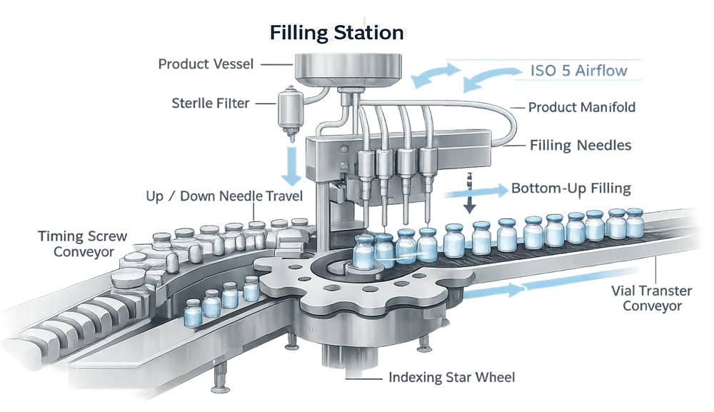
Needle and nozzle architecture
The needle arrangement affects fill accuracy, product exposure, splashing, foaming, and contamination risk. Design features may include:
- Fixed-height filling
- Bottom-up filling
- Servo-controlled needle movement
- Diving nozzles
- Needle-position verification
- Drip collection
- Product suck-back
- No-container/no-fill control
- Needle-to-container alignment
- Collision detection
- Tool-free or controlled needle changeover
Bottom-up filling may reduce splashing or foaming for some products, but the movement profile must be coordinated with container indexing and fill rate.
Needle contact with the container can generate particles or damage the needle or container. Alignment, repeatability, vibration, and safe response to a detected collision should be evaluated during qualification.
Sterile component pathways
Containers, stoppers, caps, tools, and other sterile components require defined pathways into and through the filling line. The architecture should identify:
- Component preparation method
- Sterilization or depyrogenation process
- Protected transfer route
- Maximum hold time
- Staging location
- Feed-system design
- Replenishment method
- Intervention requirements
- Empty-container and waste removal
- Component reconciliation
Sterile stoppers may enter through a transfer container, rapid transfer port, automated transfer system, or directly connected processing equipment. Once introduced, the stopper bowl, track, guides, and placement tools become indirect or direct sterility-critical surfaces.
Component pathways and transfer qualification are addressed in Qualification of Sterile Component Preparation and Transfer.
Container transport and accumulation
Transport systems may use:
- Conveyors
- Timing screws
- Star wheels
- Indexing turrets
- Pucks
- Nests
- Robotic grippers
- Magnetic transport
- Walking-beam mechanisms
The transport architecture must maintain container orientation and synchronization without generating unacceptable particles or damaging the container.
Potential risks include:
- Container contact
- Glass chipping
- Polymer abrasion
- Tipping
- Jamming
- Excessive accumulation pressure
- Incorrect pitch
- Needle collision
- Open-container backup
- Loss of container identity
Accumulation between filling and stoppering deserves particular attention because it can extend the period during which filled containers remain open. The control system should define the maximum acceptable open-container accumulation and the required response to an extended stoppage.
Stoppering and initial closure
After filling, the container should receive its initial closure under appropriate critical-zone protection. The stoppering system may include:
- Sterile stopper transfer
- Bowl or alternative feed system
- Orientation track
- Stopper-present detection
- Placement mechanism
- Insertion-force control
- Stopper-height inspection
- Reject mechanism
For liquid vial filling, the stopper is normally fully seated. For lyophilization, the stopper is partially inserted to permit vapor transfer during drying.
Incorrect stopper orientation, incomplete insertion, rebound, or displacement can affect sterility and eventual container closure integrity.
The detailed qualification of these systems is covered in Stoppering, Capping, and Sealing System Qualification.
Capping and crimping
Capping secures the stopper and completes the closure system. The station may be located inside the barrier, in a separate protected zone, or outside the principal aseptic enclosure under appropriate localized protection. Capping architecture should consider:
- Cap transfer and orientation
- Stopper-height detection before capping
- Cap-presence detection
- Crimp-force control
- Crimp-head adjustment
- Particle extraction
- Container rotation or handling
- Detection of missing or displaced stoppers
- Detection and rejection of malformed seals
Crimping can generate nonviable particles. Separating the crimping station from open-container operations and providing localized extraction may reduce the risk of particle transfer into the critical filling zone.
Where stoppered vials leave the principal aseptic zone before capping, suitable protection should be maintained until the cap is crimped. The design and qualification strategy should demonstrate that the stopper remains correctly seated during this transfer.
Closure-system performance is confirmed through appropriate inspection and container closure integrity testing.
Lyophilizer interface
For a lyophilized product, the filling-line architecture extends from partial stoppering through protected transfer and loading into the lyophilizer. The interface may include:
- Accumulation of partially stoppered vials
- Transfer under ISO 5 or Grade A protection
- Loading conveyor
- Robotic or push-bar loading
- Lyophilizer door interface
- Shelf loading
- Unloading following final stoppering
- Transfer to capping
Partially stoppered vials remain vulnerable to contamination. The transfer route and loading operation should maintain the required critical-zone protection.
The interface should also address:
- Maximum loading duration
- Line and lyophilizer speed coordination
- Vial jams and breakage
- Door-opening sequence
- Airflow at the loading interface
- Intervention access
- Recovery following loading interruption
- Product exposure during unloading
These controls are addressed in Qualification of the Lyophilization–Aseptic Filling Interface.
Single-use architecture
Single-use product-contact assemblies can reduce cleaning and sterilization requirements but introduce different lifecycle controls.
Architectural considerations include:
- Supplier design and sterilization
- Assembly configuration
- Material compatibility
- Extractables and leachables
- Shipping and storage
- Installation
- Connection method
- Leak and integrity testing
- Pump-tubing compatibility
- Hold-up volume
- Disposal
- Lot traceability
The machine must provide adequate space, routing, support, and protection for tubing, connectors, bags, filters, sensors, and filling needles.
Improvised tubing routes, unsupported connectors, pinched tubing, and tubing contact with moving machine components should be prevented through design.
See Single-Use Systems in Fill-Finish: Qualification and Lifecycle Control.
Intervention architecture
Interventions should be considered during machine design rather than developed only after installation.
The design should distinguish:
- Inherent interventions: routine actions necessary for operation, such as component replenishment or environmental-monitoring plate changes.
- Corrective interventions: actions taken in response to a fault, such as clearing a jam or replacing a displaced stopper.
For each intervention, the architecture should define:
- Access location
- Required glove port or barrier opening
- Tools
- Operator reach
- Effect on first air
- Critical surfaces at risk
- Units requiring rejection
- Line stop or speed change
- Recovery steps
- Documentation
- Representation in aseptic process simulation
Equipment should minimize intervention frequency and complexity. Sensors, automated component replenishment, online weight checks, robotic transfer, and reliable reject systems can reduce manual entry into the critical zone.
Interventions should be evaluated through airflow visualization and represented appropriately in media fill and aseptic process simulation.
Cleaning, sterilization, and bio-decontamination architecture
The line should be designed so that each controlled surface can receive its required treatment. The architecture should distinguish:
- Product-contact cleaning
- Product-contact sterilization
- Barrier interior cleaning
- Barrier bio-decontamination
- RABS sporicidal disinfection
- External equipment cleaning
- Change-part cleaning and sterilization
Design requirements may include:
- Smooth and accessible external surfaces
- Minimal ledges and recesses
- Suitable material compatibility
- Drainability
- Removal or exposure of change parts
- Sterilization-in-place connections
- Controlled assembly following sterilization
- Protection of sterile parts
- Agent-compatible sensors and cables
- Access for residue removal
- Defined cleaning and bio-decontamination boundaries
Enclosure bio-decontamination does not replace sterilization of pumps, manifolds, tubing, needles, stopper guides, or other sterility-critical product and component pathways.
Utilities and supporting systems
The line may require:
- Electrical power
- Instrument air
- Process gases
- Nitrogen
- Vacuum
- Clean steam
- Water for Injection
- Cooling water
- Chilled water
- Barrier supply and exhaust air
- Bio-decontamination agent
- Data and network connections
Utility quality, pressure, flow, capacity, and failure response should be defined based on intended use.
Product-contact gases require appropriate filtration and quality controls. Utility failure should place the line in a defined condition that protects exposed product and supports a documented disposition decision.
Automation and control architecture
The automation system coordinates machine motion, filling, component handling, inspection, rejection, barrier interfaces, alarms, and electronic records. Typical functions include:
- PLC-based sequencing
- HMI operation
- Recipe management
- Servo positioning
- Pump control
- Fill-volume calculation
- In-process weight checks
- Container tracking
- No-container/no-fill control
- Stopper and cap detection
- Reject tracking
- Alarm management
- User access
- Audit trails
- Batch-report generation
- Interface with manufacturing or laboratory systems
The system should maintain container identity through filling, inspection, and rejection. A detected defect must remain associated with the correct physical container until that container is positively rejected.
Control-system requirements should address:
- User roles
- Recipe approval
- Parameter limits
- Alarm priorities
- Interlocks
- Manual-mode controls
- Bypass management
- Audit trails
- Time synchronization
- Data retention
- Backup and recovery
- Interface failure
- Safe-state behavior
Electronic records used to support production or batch disposition should be evaluated for applicable 21 CFR Part 11 controls.
Reject systems and reconciliation
Reject systems remove containers that do not meet predefined criteria. Reasons for rejection may include:
- Missing container
- Incorrect fill
- Missing or displaced stopper
- Incorrect stopper height
- Missing cap
- Crimp defect
- Container damage
- Failed inspection
- Container affected by an intervention
- Container produced during an invalid operating state
The architecture should provide:
- Positive reject confirmation
- Secure reject collection
- Prevention of rejected-unit reentry
- Container tracking
- Reject-reason recording
- Challenge capability
- Batch reconciliation
A reject signal without confirmation that the physical unit entered the reject container is insufficient where failure could allow a nonconforming unit to remain in the batch.
Failure states and recovery
The design should define the required response to foreseeable failures, including:
- Loss of critical-zone airflow
- Barrier-pressure excursion
- Power failure
- Product-pump failure
- Fill-volume fault
- Needle collision
- Container jam
- Stopper-feed interruption
- Capping failure
- Reject-system failure
- Environmental-monitoring alarm
- Automation or communication failure
- Lyophilizer-transfer interruption
For each failure, the control strategy should determine:
- Whether filling stops immediately
- Whether containers remain open
- Which units require rejection
- Whether product flow is isolated
- Whether critical-zone protection remains functional
- Whether intervention is permitted
- Whether re-cleaning or bio-decontamination is required
- What records support batch assessment
- How restart is authorized
Restart should not be treated as a simple equipment reset. The recovery sequence must consider product exposure, open-container time, intervention effects, sterile-path status, and barrier conditions.
Architectural risk drivers
Aseptic filling-line architecture should be evaluated for interacting microbiological, mechanical, process, and data risks. Principal risk areas include:
- Loss or obstruction of first air
- Excessive open-container exposure
- Product-path integrity loss
- Uncontrolled aseptic connections
- Needle misalignment
- Mechanical particle generation
- Container breakage
- Stopper-placement failure
- Closure defects
- Incorrect reject tracking
- Unqualified interventions
- Inadequate environmental-monitoring access
- Utility failure
- Control-system desynchronization
- Incorrect recipe or change-part configuration
- Incomplete cleaning, sterilization, or bio-decontamination
- Inadequate maintenance access
The architectural risk assessment should connect each risk to a design control and later qualification evidence.
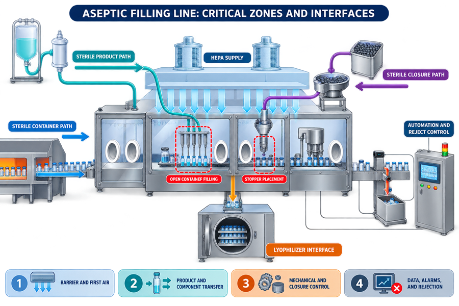
Relationship to qualification
Architecture establishes the design basis for fill-line qualification.
Qualification should verify that the installed system:
- Matches approved requirements and design documents
- Maintains the defined critical zones
- Protects sterile product and components
- Controls container transport and filling
- Performs stoppering and sealing reproducibly
- Detects and rejects nonconforming units
- Executes interventions as designed
- Enters defined safe states
- Generates complete and accurate records
- Supports cleaning, sterilization, and bio-decontamination
- Performs under representative operating conditions
Environmental performance and monitoring are addressed in Environmental Monitoring for Aseptic Filling.
Conclusion
Aseptic filling-line architecture is the integrated design of the sterile product path, container and closure pathways, critical zones, filling and closure equipment, barrier system, automation, utilities, interventions, and equipment interfaces.
A technically strong architecture minimizes exposed-product risk through engineering controls rather than relying primarily on operator technique. It provides defined critical zones, protected transfers, controlled sterile pathways, reliable component handling, verified rejection, and recoverable failure states.
The architecture becomes the foundation for equipment qualification, airflow visualization, aseptic process simulation, environmental monitoring, container closure integrity, lifecycle maintenance, and change control.