

Isolator Systems: Design, Qualification, and Lifecycle Control
Purpose and Scope
A pharmaceutical isolator is an engineered barrier system that separates an aseptic processing environment from personnel and the surrounding room. The enclosure, airflow system, glove-and-sleeve assemblies, transfer devices, controls, and bio-decontamination process function together as one contamination-control system.
An isolator can substantially reduce operator-derived contamination risk, but the technology does not eliminate the need for process design, qualification, environmental monitoring, aseptic process simulation, preventive maintenance, deviation management, and continued verification.
This article focuses on the validation lifecycle of isolators used for aseptic processing and fill-finish operations. It covers:
- System and qualification boundaries
- Open and closed isolator configurations
- Positive- and negative-pressure applications
- Airflow and pressure control
- Enclosure, glove, and transfer-system integrity
- Cleaning and bio-decontamination interfaces
- Qualification testing
- Aseptic process integration
- Routine control, change management, and requalification
Detailed development and validation of the bio-decontamination cycle are addressed separately in Barrier System Decontamination and Control Strategy.
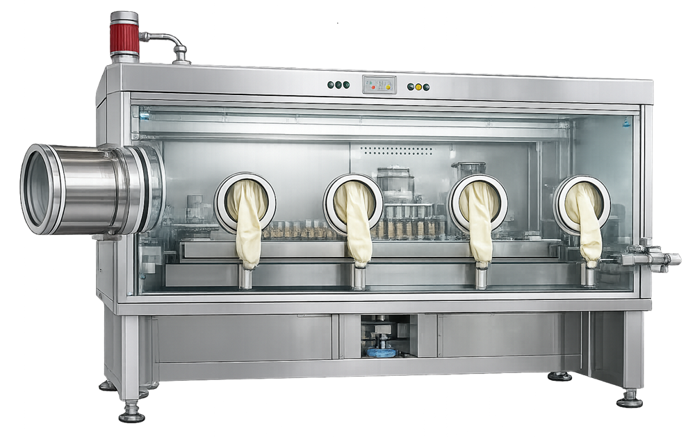
System Architecture and Validation Boundary
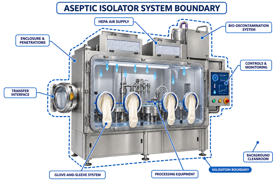
An aseptic isolator normally includes:
- A rigid enclosure with transparent viewing panels
- HEPA-filtered air supply and defined return or exhaust paths
- Pressure-control and monitoring instrumentation
- Glove-and-sleeve assemblies
- Rapid transfer ports, transfer chambers, or other controlled material interfaces
- Integrated processing equipment
- Cleaning and bio-decontamination systems
- Environmental monitoring interfaces
- Alarms, interlocks, recipes, and electronic records
- Connections to upstream and downstream equipment
The isolator boundary must be defined before qualification begins. The boundary should identify every penetration, interface, utility, control function, transfer route, and adjacent system capable of affecting aseptic conditions.
The isolator should not be qualified as an enclosure isolated from the process installed inside it. Qualification must evaluate the integrated relationship between:
- The enclosure
- Filling or processing equipment
- Air-handling components
- Product and component pathways
- Transfer systems
- Bio-decontamination equipment
- Gloves and intervention tools
- Background-room conditions
- Control and data-acquisition systems
The system boundary should be documented in the User Requirements Specification and supported by drawings, interface descriptions, instrumentation lists, control narratives, and contamination-risk assessments.
Open and Closed Isolators
The terms open and closed describe how materials enter and leave the isolator during operation. They do not describe the isolator pressure regime.
Closed Isolators
A closed isolator remains sealed during processing. Materials and product move through aseptic connections, rapid transfer ports, sterilized transfer systems, or other closed interfaces.
Closed isolators generally provide the greatest degree of physical separation, but their performance still depends on:
- Integrity of the enclosure and penetrations
- Performance of transfer interfaces
- Glove integrity
- Air-handling and pressure control
- Validated bio-decontamination
- Properly sterilized product-contact equipment
- Controlled interventions and recovery procedures
Open Isolators
An open isolator has engineered openings that permit continuous or intermittent material movement, such as container entry and exit on a filling line. Separation is maintained through airflow, pressure differentials, tunnel design, and controlled interfaces.
Qualification of an open isolator must demonstrate that the openings do not permit contamination to enter the critical zone during:
- Normal line operation
- Conveyor movement
- Component transfer
- Equipment stoppage
- Interventions
- Adjacent door movements
- Defined pressure or airflow disturbances
The FDA aseptic processing guidance distinguishes open and closed isolators and emphasizes qualification of air balance and interfaces.
Isolators and RABS Are Not Equivalent
Both technologies reduce direct operator access to critical processing areas, but their contamination-control models differ.
| Attribute | Isolator | RABS |
|---|---|---|
| Separation | High degree of enclosure separation | Barrier-assisted separation within a cleanroom |
| Internal bio-decontamination | Normally automated, validated, and cycle-controlled | Commonly relies on cleaning and manual disinfection |
| Background dependency | Reduced but not eliminated | Substantial |
| Routine access | Through gloves and validated transfer systems | Through gloves; limited door opening may be permitted |
| Enclosure leak control | Defined isolator leak-testing program | Barrier integrity managed according to design |
| Operational model | Enclosure and interfaces operate as an integrated system | Barrier operates as part of the surrounding cleanroom |
Selection between isolator and Restricted Access Barrier Systems should be based on process risk, intervention requirements, product and operator protection, transfer complexity, equipment integration, cleaning needs, and lifecycle capability—not merely on capital cost or room classification.
Positive- and Negative-Pressure Isolators
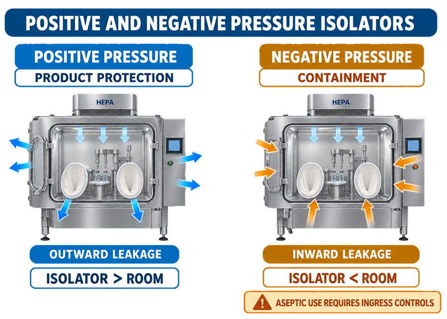
Pressure direction must be selected from the intended protection objective.
Positive-Pressure Isolators
Positive-pressure isolators maintain the enclosure at a higher pressure than the surrounding room. Leakage, if it occurs, is directed outward, helping protect the aseptic environment against room-air ingress.
This is the usual configuration for aseptic processing when product protection is the primary objective.
Qualification should establish:
- Normal operating-pressure range
- Warning and alarm limits
- Pressure stability during transfers and interventions
- Recovery after a pressure disturbance
- Differential pressure at open interfaces
- Response to fan, filter, door, or transfer-system failures
Negative-Pressure Isolators
Negative-pressure isolators direct leakage inward and may be required when containment of hazardous, potent, sensitizing, toxic, or biological materials is essential.
Negative pressure introduces an additional product-protection challenge because leakage direction is toward the enclosure. An aseptic negative-pressure application therefore requires documented justification and controls demonstrating that containment does not compromise the critical processing environment.
Possible controls include:
- Enhanced enclosure-integrity requirements
- Redundant filtration
- Controlled pressure zones
- Airlocks or transfer chambers
- Continuous pressure monitoring
- Defined failure-state control
- Demonstrated recovery following disturbances
- Assessment of contamination ingress routes
EU GMP Annex 1 states that negative-pressure isolators should be used only when containment is essential and when appropriate controls ensure that the critical zone is not compromised.
Airflow and Critical-Zone Protection
The isolator must provide the air cleanliness and airflow protection required by the process. For aseptic processing, exposed sterile product, product-contact surfaces, containers, and closures require ISO 5 protection.
Unidirectional airflow is normally expected over exposed sterile materials and critical operations. However, the required airflow configuration depends on isolator type and application. A closed isolator may use a non-unidirectional airflow pattern only when the design is supported by evidence that appropriate critical-zone protection is maintained.
Qualification should evaluate:
- HEPA-filter integrity
- Airflow volume and velocity, where relevant
- Airflow direction
- Uniformity across the critical zone
- Airflow recovery
- Airflow around equipment and intervention tools
- Return-air or exhaust-path obstruction
- Openings and transfer interfaces
- Effects of glove movement
- Effects of conveyors and moving equipment
- Effects of normal and worst-case interventions
Airflow velocity should not be treated as the sole acceptance criterion. The principal objective is demonstrated protection of critical sites and maintenance of appropriate airflow patterns during realistic operating conditions.
Airflow visualization studies should be performed under both static and dynamic conditions. Video records should clearly show:
- Airflow reaching critical sites
- Absence of room-air ingress
- Airflow behavior during representative interventions
- Recovery following disturbances
- Effects of equipment movement
- Performance at transfer openings and exit tunnels
The study should use the final equipment configuration and representative operating speeds, materials, tools, glove positions, and intervention sequences.
Background Environment
An isolator reduces reliance on the surrounding room but does not make the background environment irrelevant.
The background classification should be established from:
- Open or closed isolator design
- Number and type of openings
- Transfer-system performance
- Maintenance and setup requirements
- Consequences of enclosure or glove leakage
- Frequency of operator interaction
- Product and process risk
- Applicable regulatory expectations
FDA guidance states that an aseptic processing isolator should not be located in an unclassified room and notes that an ISO 8 background is commonly appropriate, depending on the isolator design and transfer interfaces.
For EU-regulated operations, Annex 1 generally identifies:
- At least Grade C for open isolators
- At least Grade D for closed isolators
A higher background grade may be required when justified by risk assessment and the contamination control strategy. ISO classes and EU GMP grades should not be presented as automatically interchangeable.
Background-room qualification should be coordinated with isolator testing, especially where room pressure, door operation, HVAC recovery, temperature, humidity, or air movement can affect isolator performance.
Enclosure Design and Integrity
Materials of construction should withstand repeated exposure to:
- Cleaning agents
- Sporicidal agents
- Bio-decontamination chemicals
- Process materials
- Temperature and humidity conditions
- Mechanical stress
- Routine glove manipulation
- Maintenance activities
Internal surfaces should be smooth, accessible, cleanable, and resistant to corrosion. Ledges, recesses, exposed threads, unsealed penetrations, and difficult-to-reach locations should be minimized because they can interfere with cleaning and bio-decontamination.
The enclosure-integrity program should address:
- Panels and structural joints
- Doors and access hatches
- Gaskets and seals
- Utility penetrations
- Cable and instrument penetrations
- Transfer-port connections
- Filter housings
- Glove-port assemblies
- Connections to filling or processing equipment
A pressure-decay, pressure-hold, tracer-gas, or other suitable method may be used when scientifically appropriate. The selected method, sensitivity, acceptance criteria, test conditions, and test frequency must be justified for the enclosure and its criticality.
An enclosure leak test demonstrates physical integrity under specified conditions. It does not demonstrate that internal surfaces were effectively bio-decontaminated.
Glove-and-Sleeve Systems
Gloves are among the most vulnerable parts of an isolator because they combine a physical barrier with repeated mechanical movement.
The control strategy should define:
- Glove and sleeve material
- Chemical compatibility
- Mechanical resistance
- Port and cuff design
- Maximum service life
- Replacement criteria
- Inspection frequency
- Integrity-test method and sensitivity
- Actions following a failed test
- Product-impact assessment
- Requirements after maintenance or unusual manipulation
Gloves should be visually inspected before or during each use according to procedure. Instrumented leak testing should be performed at justified intervals and after events that could affect integrity.
For operations subject to Annex 1, glove-integrity testing is generally expected at the beginning and end of each batch or campaign, with additional testing considered according to campaign length and risk.
A passing glove test does not establish that the external glove surface is microbiologically acceptable. Cleaning, disinfection, bio-decontamination exposure, and integrity testing are separate controls. Detailed expectations are provided in RABS and Isolator Glove Cleaning, Disinfection, and Integrity.
Transfer Systems and Material Flow
Every material entering or leaving an isolator creates a potential contamination pathway. Transfer design must therefore be included in qualification and process validation. Transfer methods may include:
- Rapid transfer ports
- Alpha-beta port assemblies
- Transfer chambers
- Mouseholes and exit tunnels
- Sterilized connection systems
- Double-door autoclave interfaces
- Pre-sterilized single-use assemblies
- Continuous container-entry or exit systems
Qualification should challenge:
- Connection and disconnection
- Door and port interlocks
- Mated-port integrity
- Surface exposure during docking
- Bio-decontamination of transfer chambers
- Maximum and minimum loads
- Transfer duration
- Operator technique
- Aborted or incomplete transfers
- Recovery from misalignment or alarm conditions
- Transfer of waste and rejected units
The transfer pathway must maintain the required microbiological state of the transferred item. Surface bio-decontamination of an outer package does not establish sterility of the item inside unless the complete preparation and transfer process has been validated.
Transfer qualification should be coordinated with Sterile Component Preparation and Transfer.
Cleaning and Bio-Decontamination
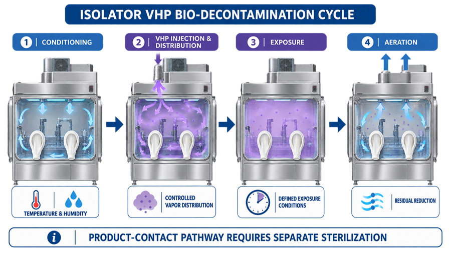
Cleaning removes residues and soils that could shield microorganisms or interfere with the bio-decontamination agent. Bio-decontamination applies a validated sporicidal process to accessible enclosure surfaces. These are related but distinct operations.
A typical vaporized hydrogen peroxide cycle may include:
- Conditioning or dehumidification
- Agent injection
- Distribution
- Exposure or dwell
- Aeration
- Confirmation of the validated endpoint
Actual phase names and control parameters vary by equipment and cycle design.
The validated cycle should address:
- Enclosure configuration
- Internal loads
- Equipment positions
- Glove positions
- Shadowed locations
- Temperature and humidity
- Agent concentration or delivery
- Exposure time
- Biological indicator locations
- Aeration capability
- Residual limits
- Alarm and abort conditions
- Cycle-record review and release
Bio-decontamination of the enclosure must not be confused with sterilization of product-contact equipment. Filling needles, product vessels, pumps, tubing, connectors, and other product-contact pathways require separately qualified sterilization, sterilizing filtration, steam-in-place, or pre-sterilized assembly controls as applicable.
Detailed cycle development, biological indicator strategy, residual control, and requalification are covered in Barrier System Decontamination and Control Strategy.
Automation, Alarms, and Data
The control system may manage:
- Airflow and fan operation
- Enclosure pressure
- Bio-decontamination recipes
- Temperature and humidity
- Agent injection and aeration
- Door and transfer-port interlocks
- Alarm generation
- Process permissives
- Cycle reports
- Electronic records
- User access
Critical functions should be identified through risk assessment and verified during qualification.
Testing should include:
- User roles and access restrictions
- Approved recipe selection
- Setpoint and alarm configuration
- Interlock logic
- Sensor failure response
- Communication failure
- Power interruption and restart
- Aborted-cycle handling
- Data retention
- Audit trails where applicable
- Backup and recovery
- Time synchronization
- Report accuracy
An acceptable bio-decontamination cycle should not be released solely because the control system displays “cycle complete.” The recorded critical parameters, alarms, deviations, and endpoint criteria must satisfy the approved cycle-release procedure.
Qualification Strategy
Qualification should follow a lifecycle approach consistent with the FDA Process Validation guidance. Testing must be based on intended use, process risk, and documented acceptance criteria.
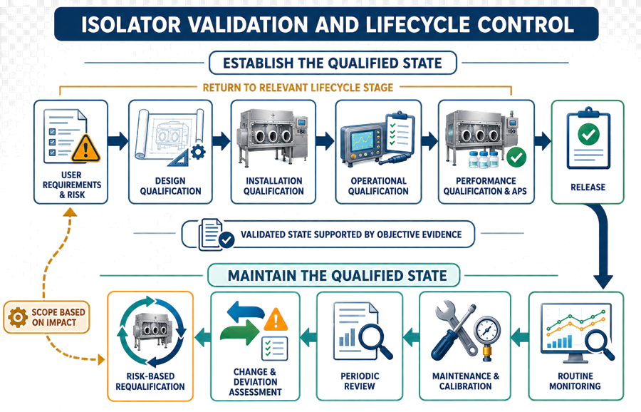
User Requirements Specification
The URS should define:
- Intended processes and products
- Open or closed configuration
- Product- and operator-protection requirements
- Pressure regime
- Critical-zone requirements
- Required processing capacity
- Intervention and access strategy
- Transfer methods
- Cleaning and bio-decontamination requirements
- Product-contact sterilization interfaces
- Environmental monitoring provisions
- Glove and enclosure-integrity requirements
- Alarm and interlock requirements
- Electronic record and data requirements
- Maintenance and calibration access
- Lifecycle and requalification expectations
Requirements should be testable or linked to documented design rationale.
Design Qualification
Design Qualification should demonstrate that the proposed design satisfies the URS and contamination-control strategy.
DQ should assess:
- System and process boundaries
- Airflow and pressure concept
- Critical-site protection
- Openings and transfer interfaces
- Equipment layout and airflow obstruction
- Glove-port location and operator reach
- Cleanability and surface accessibility
- Material compatibility
- Bio-decontamination distribution
- Product-contact sterilization strategy
- Sensor location and range
- Alarm and failure-state design
- Maintenance access
- Environmental monitoring locations
- Control-system architecture
- Applicable regulatory requirements
Intervention mapping should begin during design. Poorly positioned gloves, inaccessible components, or maintenance-intensive equipment cannot be fully corrected through procedural controls after installation.
Installation Qualification
Installation Qualification should verify the installed system against approved drawings and specifications.
IQ should include:
- Enclosure and processing-equipment installation
- Materials of construction
- Panels, seals, doors, and penetrations
- HEPA filters and air-handling components
- Gloves, sleeves, and ports
- Transfer systems
- Bio-decontamination equipment
- Utilities and drainage
- Instruments and calibration status
- Control panels and software versions
- Wiring and communication connections
- Environmental monitoring interfaces
- Identification and labeling
- Operating and maintenance documentation
- Spare-parts and preventive-maintenance requirements
Discrepancies should be resolved or formally assessed before functional testing.
Operational Qualification
Operational Qualification should challenge the isolator across approved operating ranges and defined failure conditions.
OQ normally includes:
- HEPA-filter integrity testing
- Airflow-volume and velocity testing where applicable
- Pressure-range and stability testing
- Alarm and interlock verification
- Airflow visualization
- Open-interface ingress studies
- Recovery testing
- Enclosure leak testing
- Glove-system integrity testing
- Transfer-port functional testing
- Door and hatch interlocks
- Bio-decontamination-cycle functional testing
- Sensor and control-loop verification
- Power-failure and restart testing
- Critical software-function testing
- Data and report verification
Testing should include empty, representative, and worst-case configurations where internal equipment or materials can affect airflow, pressure, or decontamination distribution.
Performance Qualification and Process Integration
Performance Qualification should demonstrate that the integrated system performs as intended under representative operating conditions.
The qualification package should evaluate:
- Routine operating configuration
- Maximum justified processing duration
- Normal and worst-case line speeds
- Representative materials and components
- Planned interventions
- Corrective interventions
- Transfer operations
- Glove manipulations
- Equipment stoppages
- Environmental monitoring
- Cleaning and changeover
- Defined recovery procedures
Engineering PQ does not replace Media Fill and Aseptic Process Simulation. APS evaluates the integrated aseptic process, including personnel, interventions, transfers, duration, equipment operation, and environmental controls.
The relationship between equipment qualification, process performance, and APS should be defined in the validation plan for the Aseptic Filling Line Architecture and Fill Line Qualification Lifecycle.
Failure Testing and Recovery
An isolator should be challenged for credible failures that could affect aseptic conditions. Examples include:
- Loss of enclosure pressure
- Fan or airflow failure
- HEPA-filter alarm
- Door or transfer-port interlock failure
- Glove breach
- Power interruption
- Control-system restart
- Bio-decontamination-cycle abort
- Aeration failure
- Sensor failure
- Conveyor stoppage
- Communication loss
- Environmental monitoring interruption
For each failure, procedures should define:
- Automatic system response
- Alarm priority
- Permitted operator action
- Product disposition
- Recovery requirements
- Need for repeat cleaning or bio-decontamination
- Required integrity or environmental testing
- Documentation and quality-unit review
Successful engineering recovery does not automatically establish that affected product remains acceptable. Product-impact decisions must consider the event, location, duration, exposed product, pressure and airflow data, environmental monitoring, intervention history, and validated recovery strategy.
Routine Control and Continued Verification
Routine control should demonstrate that the qualified state is maintained rather than assumed.
The program should include:
- Review of pressure and airflow trends
- Review of bio-decontamination cycle records
- Alarm and deviation trending
- Glove visual inspection and leak testing
- Enclosure-integrity testing
- HEPA-filter testing
- Instrument calibration
- Preventive maintenance
- Transfer-system inspection
- Cleaning verification
- Environmental monitoring
- Intervention review
- Training and operator qualification
- Periodic review of electronic records
- Assessment of recurring minor failures
Environmental monitoring should be based on process risk and representative critical locations. Reduced personnel presence inside an isolator can reduce contamination risk, but it does not justify eliminating meaningful monitoring. The monitoring program should be coordinated with Environmental Monitoring for Aseptic Filling.
Change Control and Requalification
Changes must be evaluated before implementation through formal GMP Change Control and Validation Impact Assessment.
Potential requalification triggers include:
- Enclosure modification
- Relocation of processing equipment
- HEPA-filter replacement
- Airflow or pressure changes
- Glove-port modification
- New glove material
- Transfer-system modification
- Bio-decontamination generator or recipe change
- Sensor relocation or replacement
- Software or control-logic changes
- New product or load configuration
- Increased batch or campaign duration
- New intervention
- Maintenance affecting enclosure integrity
- Repeated alarms, failures, or adverse trends
The requalification scope should be risk-based and may range from targeted testing to repeat OQ, PQ, bio-decontamination qualification, airflow visualization, or APS. The rationale should be documented using the principles described in Risk-Based Requalification of GMP Equipment.
Regulatory Framework
In the United States, isolator design and validation support compliance with:
- 21 CFR 211.42, covering facility design and controls for aseptic processing
- 21 CFR 211.63, requiring suitable equipment design, size, and location
- 21 CFR 211.67, covering equipment cleaning and maintenance
- 21 CFR 211.113(b), requiring procedures and validation to prevent microbiological contamination
- FDA Guidance for Industry: Sterile Drug Products Produced by Aseptic Processing
For facilities supplying the European market, EU GMP Annex 1 provides specific expectations for isolator design, background classification, glove testing, airflow studies, and automated bio-decontamination.
ISO 14644-7:2004 provides requirements for separative devices, including isolators. It should be used with applicable pharmaceutical regulations and guidance; it does not independently define the complete aseptic validation strategy. A replacement edition is under development, but the 2004 edition remains the published standard at the time of this review.
Common Validation Deficiencies
Common deficiencies include:
- Qualifying the enclosure separately from the installed process
- Incomplete definition of system boundaries
- Treating open or closed configuration as equivalent to pressure direction
- Relying only on airflow velocity measurements
- Smoke studies that omit dynamic interventions
- Failure to challenge transfer openings
- Inadequate glove-integrity strategy
- Assuming a leak test proves microbiological control
- Confusing enclosure bio-decontamination with product-contact sterilization
- Inadequate worst-case load definition for bio-decontamination
- Missing failure and recovery testing
- Uncontrolled changes to equipment position or airflow obstruction
- Insufficient review of alarms and cycle data
- Requalification based only on calendar frequency
- Failure to connect equipment qualification with APS and routine operations
Conclusion
An isolator is an integrated contamination-control system, not simply a sealed cabinet placed around a filling line. Its validated state depends on the coordinated performance of the enclosure, airflow, pressure, gloves, transfer systems, processing equipment, cleaning, bio-decontamination, product-contact sterilization, automation, environmental monitoring, and operating procedures.
Effective qualification demonstrates that these controls remain protective during routine operations, worst-case interventions, transfers, disturbances, and credible failures. Lifecycle control then maintains that evidence through monitoring, maintenance, change assessment, investigation, periodic review, and risk-based requalification.