

Single-Use Fill-Finish System Qualification
Purpose and scope
Single-use systems used in aseptic fill-finish replace some reusable product-contact equipment with disposable bags, tubing, filters, connectors, pump tubing, manifolds, and filling assemblies.
Their use can reduce cleaning, cleaning validation, assembly, and sterilization activities associated with fixed stainless-steel systems. It does not eliminate validation responsibility. The primary risks shift toward:
- Material compatibility.
- Extractables, leachables, adsorption, and absorption.
- Supplier dependency.
- Irradiation or other sterilization controls.
- Packaging and shipping integrity.
- Configuration accuracy.
- Manual assembly and connections.
- Mechanical fragility.
- Pre-use and post-use integrity.
- Particulate contamination.
- Operator handling.
- Supplier and material changes.
This article addresses single-use fluid paths used for:
- Sterile bulk-product holding.
- Formulated product transfer.
- Sterilizing-grade filtration.
- Post-filtration sterile hold.
- Sterile pooling.
- Transfer to the filling machine.
- Pumping and filling.
- Representative filling needles and manifolds.
Upstream bioprocessing systems are outside the primary scope unless they form part of the final sterile product pathway or directly interface with fill-finish operations.
Regulatory position
Single-use systems are not subject to a separate FDA validation regulation. They are controlled through the applicable CGMP requirements for equipment, product-contact materials, sterile processing, components, laboratory controls, and production procedures. Relevant requirements include:
- 21 CFR 211.63 for equipment design, size, and location.
- 21 CFR 211.65 for product-contact surface suitability.
- 21 CFR 211.67 for equipment cleaning, maintenance, and sterilization where applicable.
- 21 CFR 211.84 for testing, examination, and release of applicable incoming components.
- 21 CFR 211.113 for control of microbiological contamination.
- FDA Guidance for Industry: Sterile Drug Products Produced by Aseptic Processing.
EU GMP Annex 1 addresses single-use systems directly in paragraphs 8.131–8.139. It identifies risks associated with product-contact interactions, fragility, manual operations, assembly complexity, filter integrity testing, holes, leakage, packaging removal, particles, supplier control, sterilization, and sterile connections. See EU GMP Annex 1.
Applicable technical references may also include:
- USP
<665>Plastic Components and Systems Used to Manufacture Biopharmaceutical Drug Substances and Biopharmaceutical and Pharmaceutical Drug Products. - USP
<1665>Characterization of Plastic Components and Systems Used to Manufacture Biopharmaceutical Drug Substances and Biopharmaceutical and Pharmaceutical Drug Products. - ISO 11137, when radiation sterilization is used and its application is appropriate.
- Supplier-specific sterilization, extractables, integrity, and functional qualification documentation.
System architecture and sterile-boundary definition
A typical single-use fill-finish system may include:
- Product-hold or surge bag.
- Tubing and manifolds.
- Sterilizing-grade filter.
- Vent filter.
- Sampling connection.
- Aseptic connector or tube weld.
- Sterile disconnect.
- Pressure sensor.
- Single-use flowmeter.
- Pump tubing or disposable pump head.
- Filling manifold.
- Filling needles.
- Clamps, plugs, valves, and protective caps.
The sterile boundary should be defined on an approved drawing or configuration record. The drawing should identify:
- Sterile and nonsterile portions.
- Product-contact surfaces.
- Open and closed interfaces.
- Sterilizing-grade filters.
- Aseptic connections.
- Sterile disconnects.
- Sampling points.
- Vent and pressure-relief paths.
- Filling needles.
- Points at which the boundary can be opened or breached.
A disposable assembly is not automatically a closed system. Closed-system status depends on the system design, integrity, connection technology, operating procedures, and evidence that the boundary remains intact during use.
The entire assembly also does not necessarily require placement within an ISO 5 or Grade A environment. The filling needles, exposed sterile connections, and open-container interfaces require the applicable critical-zone protection. Other closed portions may be located in a different environment when their integrity and transfer strategy have been justified.
The design should be coordinated with the aseptic filling line architecture and the site contamination control strategy.
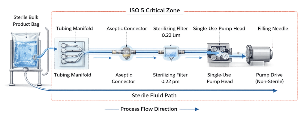
The illustration is conceptual. Its ISO 5 boundary should not be interpreted as a universal requirement for every component in every single-use installation.
Intended use and design requirements
The intended use should be defined before selecting a supplier assembly. Requirements should address:
- Product identity and formulation.
- Batch and hold volume.
- Minimum and maximum flow.
- Operating and transient pressure.
- Product temperature.
- Contact time.
- Maximum process duration.
- Product viscosity.
- Pump type and speed.
- Filter area and allowable differential pressure.
- Connection and disconnection methods.
- Sampling requirements.
- Mixing or recirculation, where applicable.
- Storage and transportation conditions.
- Freeze–thaw exposure, where applicable.
- Sterilization method and dose range.
- Required shelf life.
- Cleanroom transfer and debagging.
- Particulate and bioburden controls.
- Extractables and leachables requirements.
- Required supplier documentation.
- Assembly identification and traceability.
- Pre-use and post-use integrity testing.
Requirements should distinguish the disposable assembly from the reusable support equipment. Reusable equipment may include:
- Pump drives.
- Scales or load cells.
- Bag holders.
- Pressure-monitoring instruments.
- Control panels.
- Automated clamps.
- Filling-machine drives.
- Data-acquisition systems.
Reusable equipment remains subject to conventional installation and functional qualification.
Supplier qualification and design control
Supplier oversight is a central element of single-use system qualification because the user normally relies on the supplier for:
- Resin and material control.
- Component manufacturing.
- Assembly.
- Environmental controls.
- Bioburden control.
- Packaging.
- Sterilization.
- Inspection.
- Lot release.
- Change notification.
Supplier qualification should evaluate:
- Quality-system status.
- Manufacturing locations.
- Critical sub-suppliers.
- Material and resin traceability.
- Assembly controls.
- Environmental and bioburden controls.
- Sterilization validation.
- Packaging validation.
- Integrity testing.
- Extractables data.
- Transportation studies.
- Shelf-life justification.
- Deviation and complaint management.
- Change-notification procedures.
- Business continuity.
A quality agreement should define responsibilities for:
- Approved materials and components.
- Sterilization.
- Certificates and release documentation.
- Nonconformances.
- Investigations.
- Complaint handling.
- Change notification.
- Audit access.
- Record retention.
- Obsolescence and discontinuation.
Supplier qualification does not replace the user’s responsibility to demonstrate that the system is suitable for the actual product and process.
Sterilization and packaging control
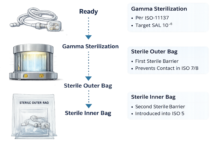
Many sterile single-use assemblies are sterilized by gamma irradiation or electron beam. Other validated sterilization methods may be used depending on the assembly and supplier.
The user should evaluate:
- Applied sterilization standard.
- Validated sterilization-dose range.
- Sterility assurance claim.
- Product-family or assembly-family rationale.
- Bioburden controls.
- Dose mapping.
- Minimum-dose delivery.
- Maximum-dose effect on materials.
- Sterilization location.
- Irradiation indicators and records.
- Requalification or sterilization-dose audit strategy.
- Packaging configuration.
- Approved shelf life.
Where gamma irradiation is used, the evaluation should be coordinated with the principles described in gamma sterilization and radiation sterilization validation.
Evidence of sterilization should be available for each applicable assembly lot or unit, consistent with the approved supplier documentation and receiving controls.
A supplier certificate does not establish that:
- The correct assembly was received.
- The packaging remains intact.
- Shipping damage did not occur.
- The assembly is within its approved shelf life.
- Storage requirements were maintained.
- The assembly is suitable for the intended product and process.
Packaging layers and classified-area transfer
Single-use assemblies may be supplied in double- or triple-bagged configurations to support staged transfer through classified areas.
The transfer procedure should define:
- Where each packaging layer is removed.
- Which surfaces may enter each area.
- Required disinfection.
- Required personnel and glove practices.
- Temporary staging conditions.
- Maximum transfer or exposure time.
- Protection of the final sterile barrier.
- Response to damaged or wet packaging.
Packaging-layer terminology should be based on the qualified supplier configuration. The exterior of an outer bag should not be assumed to remain sterile after shipping and warehouse handling, even when the complete assembly was irradiated.
The final protective layer should be opened only under conditions appropriate for the sterile assembly and connection being performed.
Material compatibility and product interaction
Product-contact materials may include:
- Polyethylene.
- Polypropylene.
- Ethylene vinyl acetate.
- Silicone.
- Thermoplastic elastomers.
- Fluoropolymers.
- Polycarbonate.
- Adhesives.
- Lubricants.
- Colorants and processing aids.
The compatibility assessment should consider more than visible material damage. Potential interactions include:
- Extractables and leachables.
- Adsorption of product components.
- Absorption into polymer materials.
- Protein aggregation.
- Product loss.
- Particle shedding.
- Gas permeability.
- Moisture transfer.
- Changes in pH, potency, or purity.
- Surface binding of low-concentration or high-potency materials.
The assessment should reflect actual process conditions, including:
- Product formulation.
- Concentration.
- pH.
- Solvent or surfactant content.
- Contact temperature.
- Contact duration.
- Surface-area-to-volume ratio.
- Irradiation dose.
- Storage conditions.
- Recirculation or mixing.
- Freeze–thaw exposure.
- Cumulative contact across multiple components.
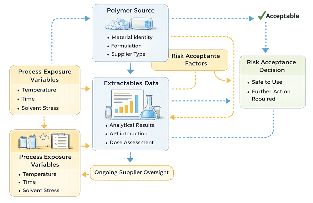
Extractables and leachables
Extractables studies evaluate chemical entities that may be released from materials under defined laboratory conditions. Leachables are chemical entities that migrate into the actual product under normal or accelerated process and storage conditions.
Supplier extractables data may support the assessment when:
- The tested material is representative of the supplied component.
- The sterilization condition is representative.
- Extraction solvents and conditions provide applicable coverage.
- The analytical methods and reporting thresholds are understood.
- The supplier’s material formulation remains controlled.
Supplier data should be assessed for applicability rather than accepted solely because it is available.
A product-specific assessment should consider:
- Actual product formulation.
- Maximum contact time.
- Maximum temperature.
- Maximum surface-area-to-volume ratio.
- Sterilization-dose range.
- Cumulative exposure across the fluid path.
- Patient dose.
- Route of administration.
- Toxicological thresholds.
- Potential interaction with the active ingredient.
Dedicated leachables studies may be required when supplier extractables data and process knowledge do not provide sufficient assurance.
Mechanical integrity and operational limits
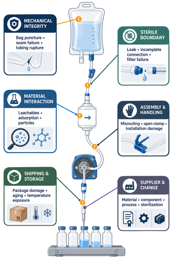
Single-use systems may be more vulnerable than fixed piping to handling damage, installation errors, pressure excursions, and fatigue.
Potential failure modes include:
- Bag puncture.
- Bag-film damage.
- Port or seam failure.
- Tubing rupture.
- Tubing creep.
- Pump-tubing fatigue.
- Kinked tubing.
- Incorrect clamp position.
- Connector misalignment.
- Incomplete connector engagement.
- Improper tube weld.
- Filter-housing cracking.
- Excessive filter differential pressure.
- Loose fittings.
- Damage during debagging.
- Shipping or storage damage.
- Loss of integrity during freezing or thawing.
The qualification program should establish applicable limits for:
- Maximum allowable working pressure.
- Differential pressure.
- Flow.
- Pump speed.
- Filling duration.
- Hold duration.
- Bag volume.
- Supported load.
- Temperature.
- Freeze–thaw cycles.
- Connection count.
- Tubing bend radius.
- Shelf life.
- Installation and handling.
A rated component limit should not automatically become the process operating limit. The qualified operating range should include an appropriate relationship between routine conditions, alarms, action limits, and supplier-rated limits.
Connection and disconnection qualification
Connections are frequently among the highest-risk operations in a single-use fluid path. Connection methods may include:
- Preassembled sterile connections.
- Aseptic mechanical connectors.
- Tube welding.
- Heat sealing.
- Sterile disconnect devices.
- Connections performed under Grade A or ISO 5 protection.
Qualification should evaluate:
- Component compatibility.
- Tubing material and dimensions.
- Equipment settings.
- Connection alignment.
- Engagement confirmation.
- Connection force.
- Weld or seal quality.
- Mechanical strength.
- Leakage.
- Operator technique.
- Access and ergonomics.
- Environmental protection.
- Connection under representative process conditions.
Worst-case challenges may include:
- Minimum and maximum tubing dimensions.
- Maximum pressure.
- Maximum connection count.
- Difficult access.
- Low-light or restricted-visibility conditions.
- Representative glove use.
- Different qualified operators.
- Connection after the maximum permitted staging time.
- Connection following transportation or temperature conditioning.
Where connections remain part of the sterile pathway, representative manipulations should be incorporated into aseptic process simulation.
Qualification strategy
Design qualification
Design Qualification should demonstrate that the selected assembly can meet its intended use and control the identified product-quality risks. The assessment should cover:
- Approved bill of materials.
- Product-contact materials.
- Component and sub-supplier specifications.
- Sterile-boundary definition.
- Assembly configuration.
- Sterilization suitability.
- Packaging configuration.
- Material compatibility.
- Extractables and leachables.
- Adsorption and absorption.
- Pressure and temperature limits.
- Flow and pump compatibility.
- Connection technology.
- Filter compatibility.
- Shipping and shelf life.
- Supplier controls.
- Change-notification requirements.
The approved configuration should be represented by a controlled drawing, part number, revision, and bill of materials.
Reusable equipment qualification
Reusable support equipment should undergo appropriate qualification. Depending on the system, this may include:
- Bag holders.
- Pump drives.
- Scales.
- Pressure instruments.
- Flowmeters.
- Automated clamps.
- Filling-machine interfaces.
- Controls and software.
- Alarms and interlocks.
Qualification should verify installation, calibration, operating ranges, failure responses, data handling, and interaction with the disposable assembly.
Disposable assembly verification
A new disposable assembly is installed for each batch or campaign. Therefore, traditional Installation Qualification is generally performed for the reusable system, while each disposable assembly receives documented configuration and installation verification. Verification should include:
- Correct assembly part number and revision.
- Correct lot number.
- Sterilization status.
- Expiration date.
- Packaging integrity.
- Approved certificate documentation.
- Correct orientation.
- Tubing routing.
- Clamp positions.
- Connector status.
- Filter identity.
- Vent and pressure-relief paths.
- Sensor installation.
- Pump-tubing installation.
- Filling-needle configuration.
- Absence of visible damage.
- Traceability in the batch record.
Operational qualification
Operational Qualification should challenge the system across its approved operating range. Potential challenges include:
- Minimum and maximum flow.
- Minimum and maximum pump speed.
- Maximum expected pressure.
- Transient pressure excursion.
- Maximum filter differential pressure.
- Longest operating duration.
- Maximum hold time.
- Minimum and maximum bag volume.
- Pump start and stop.
- Line blockage or closed clamp.
- Sensor failure.
- Alarm activation.
- Power interruption.
- Representative connection and disconnection.
- Leakage or integrity challenge.
- Incorrect installation, where detectable.
- Recovery following a controlled interruption.
Surrogate fluids may be used when their viscosity, density, surface tension, temperature, and other relevant properties adequately represent the commercial process.
Performance qualification
Performance Qualification should demonstrate that the complete system performs reproducibly under representative production conditions. PQ should cover, as applicable:
- Approved commercial configuration.
- Qualified operators.
- Representative product or justified surrogate.
- Normal operating ranges.
- Justified worst-case conditions.
- Full process duration.
- Maximum hold time.
- Filter and connection performance.
- Pump and filling accuracy.
- Pressure and flow behavior.
- Assembly integrity.
- Sampling and interventions.
- Batch documentation.
- Post-use examination.
PQ should be integrated with the fill line qualification lifecycle but should remain distinct from sterilization validation, filter validation, analytical testing, and APS.
Integrity testing and inspection
Integrity controls should be selected according to assembly risk and technical capability. Possible controls include:
- Incoming packaging inspection.
- Pre-installation visual inspection.
- Post-installation visual inspection.
- Pressure-hold or pressure-decay testing.
- Vacuum-based integrity testing.
- Connection verification.
- Weld or seal inspection.
- Post-use system inspection.
- Sterilizing-grade filter integrity testing.
- Leak monitoring during operation.
Not every assembly can be pressure tested without modification or risk. The need, method, timing, pressure, acceptance criteria, and potential effect of testing should be established during qualification.
Integrity testing of the overall assembly should not be confused with sterilizing-grade filter integrity testing. Filter integrity has separate method, validation, timing, and acceptance requirements.
A visual inspection can detect some forms of damage but does not demonstrate the absence of small leaks.
Receiving, storage, and release
Receiving controls should verify:
- Approved supplier.
- Correct part number and revision.
- Lot identity.
- Quantity.
- Sterilization evidence.
- Packaging condition.
- Shipping condition.
- Expiration date.
- Required certificates.
- Approved storage conditions.
Assemblies should remain in controlled status until the required documentation and inspection have been accepted.
Storage controls should address:
- Temperature and humidity, where specified.
- Protection from ultraviolet light.
- Carton stacking.
- Sharp objects.
- Pests and contamination.
- Material segregation.
- Stock rotation.
- Shelf-life status.
- Protection from crushing or deformation.
Aseptic process simulation
An assembly that forms part of the aseptic pathway should be represented in APS using the commercial configuration or a scientifically justified equivalent. APS should include applicable activities such as:
- Debagging.
- Assembly installation.
- Aseptic connection.
- Tube welding.
- Sterile disconnection.
- Product or media transfer.
- Sterile hold.
- Filter use.
- Sampling.
- Filling.
- Routine interventions.
- Corrective interventions.
- Maximum process duration.
- Maximum number of connections.
Critical manual assembly and connection operations should be performed by qualified operators and represented under realistic conditions.
APS demonstrates microbiological process capability. It does not replace mechanical qualification, material compatibility assessment, sterilization validation, or supplier qualification.
Routine operation and batch review
Before use, personnel should confirm:
- Assembly identity and revision.
- Lot and sterilization status.
- Expiration date.
- Packaging condition.
- Correct installation.
- Connection status.
- Clamp and valve positions.
- Tubing routing.
- Filter identity and integrity-test status.
- Instrument calibration.
- Approved process recipe.
- Required system checks.
Batch review should evaluate:
- Assembly traceability.
- Installation verification.
- Connection records.
- Pressure and flow data.
- Filter-integrity results.
- Alarms.
- Leaks.
- Product loss.
- Interventions.
- Deviations.
- Post-use inspection.
- Supplier complaints or nonconformances.
Deviations and failure response
Procedures should define the response to:
- Damaged packaging.
- Expired assembly.
- Incorrect configuration.
- Missing sterilization evidence.
- Incomplete connection.
- Failed weld or seal.
- Leak.
- Bag or tubing rupture.
- Pressure excursion.
- Filter-integrity failure.
- Unexpected particles.
- Product-contact material discrepancy.
- Supplier change not previously assessed.
The investigation should determine:
- When the failure occurred.
- Whether the sterile boundary was compromised.
- Which product was potentially affected.
- Whether the failure was detectable during operation.
- Whether product segregation is possible.
- Whether similar assemblies or lots are affected.
- Whether supplier investigation is required.
- Whether continued use of related inventory is justified.
A successful repeat connection, integrity test, or visual inspection does not erase the original failure.
Continued verification and periodic review
Continued verification should trend:
- Leaks.
- Bag, tubing, and connector failures.
- Weld and seal failures.
- Filter-integrity failures.
- Assembly errors.
- Installation discrepancies.
- Pressure excursions.
- Product loss.
- Particulate observations.
- Packaging damage.
- Supplier deviations.
- Complaints.
- Lot rejection.
- Changes and obsolescence.
- Operator qualification.
- APS observations.
Periodic review should evaluate whether:
- The approved design remains current.
- Supplier documentation remains adequate.
- Material and component specifications remain unchanged.
- Sterilization evidence remains applicable.
- Extractables data remain representative.
- Operating ranges remain valid.
- Failure trends remain acceptable.
- Change notifications were properly assessed.
- Requalification is required.
Change control and requalification
Potential change triggers include:
- Resin or polymer formulation.
- Product-contact material.
- Component manufacturer.
- Manufacturing location.
- Assembly process.
- Sterilization method.
- Irradiation facility.
- Sterilization-dose range.
- Packaging configuration.
- Shelf life.
- Connector geometry.
- Tubing dimensions.
- Bag-film construction.
- Filter type.
- Assembly drawing.
- Part number or revision.
- Product formulation.
- Contact time or temperature.
- Flow or pressure.
- Filling duration.
- Storage or transportation conditions.
- Reusable support equipment.
- Connection method.
Each change should undergo a documented change-control impact assessment.
The outcome may include:
- Documentation update.
- Supplier-document review.
- Incoming inspection changes.
- Compatibility assessment.
- Extractables or leachables assessment.
- Mechanical testing.
- Integrity testing.
- Targeted functional qualification.
- APS inclusion.
- Partial requalification.
- Comprehensive requalification.
The scope should follow the site’s risk-based requalification process.
Common deficiencies
Common deficiencies include:
- Assuming that disposable means prequalified.
- Treating every single-use assembly as a closed system.
- Failing to define the sterile boundary.
- Applying ISO 5 requirements to the entire assembly without process justification.
- Relying entirely on supplier certificates.
- Failing to evaluate critical sub-suppliers.
- Accepting supplier extractables data without assessing applicability.
- Ignoring adsorption, absorption, particles, or gas permeability.
- Treating supplier-rated limits as qualified process limits.
- Failing to qualify connections and operators.
- Using traditional IQ terminology for every batch-installed assembly without distinguishing configuration verification.
- Failing to represent connections and handling in APS.
- Inadequate packaging and receiving inspection.
- Poor assembly revision and bill-of-material control.
- Inadequate change-notification agreements.
- No assessment of shipping, storage, or shelf life.
- Failure to investigate repeat leaks or connection problems as trends.
Conclusion
Single-use fluid paths can reduce cleaning, assembly, and cross-contamination risks in aseptic fill-finish operations. They introduce different risks involving materials, suppliers, sterilization, packaging, configuration, mechanical integrity, connections, and operator handling.
A defensible lifecycle program combines intended-use requirements, supplier qualification, design qualification, reusable-equipment qualification, disposable-assembly verification, functional challenge testing, performance qualification, APS, incoming release, continued verification, and change control.
Disposable status changes the validation strategy. It does not reduce the need for documented evidence that the sterile fluid path remains suitable, correctly configured, integral, and controlled throughout use.