

Biosafety Cabinets vs Laminar Flow Hoods
Biosafety cabinets and laminar flow hoods can both provide HEPA-filtered airflow over a controlled work zone, but they serve different protection objectives and operate through different airflow principles. A laminar flow hood is primarily intended to protect the product or process. A Class II biosafety cabinet combines product protection with personnel and environmental protection against appropriate particulate or biological hazards.
Selection cannot be based only on whether the work zone can meet ISO 5 particle limits. The intended process, exposed critical sites, material hazards, aerosol potential, exhaust requirements, work-zone arrangement, cleaning needs, and facility interfaces must all be evaluated. An unsuitable selection cannot be corrected merely by performing additional qualification testing.
This article addresses equipment selection, airflow architecture, protection functions, facility integration, and the design-review evidence needed before qualification. Detailed certification, functional testing, and requalification are addressed separately in BSC and LFH certification, qualification, and lifecycle control.
Intended Use and Validation Relevance
Selection of a biosafety cabinet or laminar flow hood is an early validation decision. The selected system establishes the protection strategy and influences:
- User requirements
- Equipment and facility design
- Exhaust-system requirements
- Work-zone dimensions
- Alarm and monitoring functions
- Installation location
- Cleaning and disinfection provisions
- Qualification tests
- Operational restrictions
- Maintenance access
- Change-control requirements
The intended use should be defined before equipment selection. At minimum, it should identify:
- The process performed inside the unit
- The product, component, or material being handled
- Whether sterile product or critical surfaces are exposed
- Required product protection
- Required personnel protection
- Required environmental protection
- Biological, potent, toxic, sensitizing, or otherwise hazardous materials
- Potential for aerosols, droplets, powders, or vapors
- Normal and foreseeable abnormal operations
- Container, instrument, and equipment dimensions
- Number and position of operators
- Required utilities and exhaust connections
- Cleaning and disinfection requirements
- Waste-removal strategy
- Applicable regulatory and technical requirements
These inputs should be documented in the user requirements specification or equivalent intended-use document. A risk-based assessment should then determine the required protection functions and the most suitable equipment architecture.
Protection Objectives
The first selection question is not whether an LFH or BSC is more sophisticated. It is which protection functions the process requires.
Product protection
Product protection limits contamination of exposed sterile product, sterile components, critical surfaces, or other contamination-sensitive materials. It depends on HEPA-filtered airflow reaching critical sites before contacting hands, nonsterile surfaces, or other contamination sources.
Product protection may be provided by:
- Horizontal unidirectional airflow
- Vertical unidirectional airflow
- Class II BSC downflow
- Other qualified localized airflow systems
Particle classification alone does not demonstrate effective product protection. The airflow must also remain suitable under the actual equipment arrangement, operator movements, material transfers, and interventions.
Personnel protection
Personnel protection limits operator exposure to aerosols, droplets, powders, or other materials released by the process.
A conventional laminar flow hood does not provide engineered personnel containment. Air leaving the work zone generally enters the surrounding room. In a horizontal LFH, the airflow is directed toward the operator.
A Class II BSC draws room air inward through the front opening. This inflow helps capture process-generated particulate contamination before it can escape into the operator’s breathing zone. Personnel protection depends on correct inflow, sash position, grille clearance, exhaust performance, and operator technique.
Environmental protection
Environmental protection limits discharge of process-generated particulate contamination into the surrounding room or exhaust system.
Class II BSC exhaust air passes through a HEPA filter before discharge. This provides environmental protection against particles and appropriate biological hazards. HEPA filtration does not remove gases or chemical vapors. Chemical hazards therefore require a separate assessment of exhaust configuration, concentration, compatibility, and applicable safety requirements.
Protection comparison
| Equipment | Product protection | Personnel protection | Environmental protection | Principal limitation |
|---|---|---|---|---|
| Horizontal LFH | Yes, when properly designed and operated | No | No | Work-zone air moves toward the operator |
| Vertical LFH | Yes, when properly designed and operated | Generally no | Generally no | Objects and operator movement can disrupt downflow |
| Class II Type A2 BSC | Yes | Yes for appropriate particulate and biological hazards | Yes for appropriate particulate and biological hazards | A portion of cabinet air is recirculated |
| Class II Type B2 BSC | Yes | Yes when properly installed and operated | Yes through total exhaust | Performance depends on the building exhaust system |
Actual protection depends on the selected unit, installation, certification, process configuration, operating procedures, and continued maintenance.
Airflow Architecture
Laminar flow hoods and Class II biosafety cabinets use HEPA-filtered airflow differently.
In an LFH, filtered air passes across the work zone and then generally discharges into the surrounding room. Product protection is achieved by supplying clean air to critical sites and displacing room contamination away from the controlled work area.
In a Class II BSC, room air is drawn inward through the front opening while HEPA-filtered downflow is supplied over the work zone. Air is captured through internal grilles, filtered, and either partially recirculated or completely exhausted, depending on cabinet type.
The illustration below shows the principal airflow differences among horizontal LFHs, vertical LFHs, and Class II BSCs.
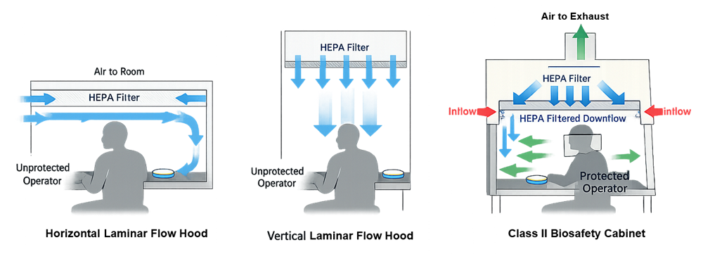
These airflow patterns define the protection functions, operating limitations, and qualification requirements of each system.
Laminar Flow Hoods
A laminar flow hood—also called a laminar airflow workbench or clean bench—is intended primarily to provide a clean, controlled work zone for contamination-sensitive materials.
The term “laminar flow” is commonly used in equipment descriptions, although “unidirectional airflow” is generally the more appropriate technical term for airflow moving in a controlled direction with sufficiently uniform velocity. Actual airflow behavior must be demonstrated rather than assumed from the equipment name.
Horizontal laminar flow hoods
A horizontal LFH normally supplies HEPA-filtered air from the rear of the work zone toward the operator.
Critical sites positioned close to the rear filter can receive unobstructed first air. Materials placed between the filter and a critical site, however, can create downstream airflow shadows. Hands, packaging, waste, or nonsterile items located upstream of exposed sterile components can contaminate the air before it reaches the critical site.
Horizontal airflow can be suitable for small, low-profile, nonhazardous aseptic manipulations when the work can be arranged in a consistent rear-to-front sequence.
Its principal limitations are:
- Airflow is directed toward the operator.
- Process-generated aerosols or vapors may enter the room.
- Large objects can create long downstream airflow shadows.
- Deep or vertically complex equipment arrangements can be difficult to protect.
- It provides no engineered inflow containment at the front opening.
A horizontal LFH should not be selected when the process presents a credible personnel or environmental hazard.
Vertical laminar flow hoods
A vertical LFH supplies HEPA-filtered air downward over the work surface. Air typically exits through the open front or through a combination of open and internal return pathways, depending on the equipment design.
Vertical airflow can accommodate taller equipment and may reduce the long horizontal shadow created by an object placed directly in front of a rear-mounted filter. However, objects positioned under the HEPA filter still divide and redirect the airflow. Turbulence or recirculation can develop below or beside large objects, around operator arms, and near the edges of the qualified work zone.
Critical considerations include:
- Maintaining unobstructed airflow above critical sites
- Avoiding vertical stacking
- Keeping return grilles clear
- Controlling operator arm movement
- Preventing room cross-drafts
- Defining the usable work-zone boundary
- Evaluating heat-generating equipment
A vertical LFH should not be assumed to provide personnel containment merely because its primary airflow direction is downward. Unless the unit is specifically designed and verified for containment, air leaving the work zone can still carry contaminants into the room.
Airflow shadowing and disruption
Equipment, supplies, hands, waste containers, and instruments influence airflow. Even when the empty hood meets its airflow specification, an unsuitable operating configuration can prevent first air from reaching exposed critical sites.
The illustration below compares airflow shadowing in horizontal and vertical LFHs.
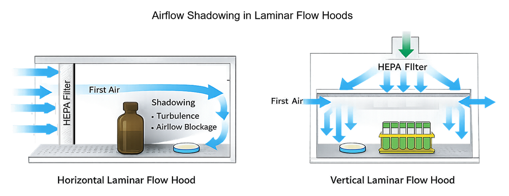
The qualification strategy should therefore evaluate the hood with representative equipment and materials in place. Operational airflow visualization studies should demonstrate that the approved configuration maintains protection during routine manipulations and anticipated interventions.
Class II Biosafety Cabinets
A Class II BSC is a dynamically balanced airflow system intended to provide product, personnel, and environmental protection for appropriate particulate and biological hazards.
Its principal airflow functions are:
- Inward airflow through the front opening to support personnel protection
- HEPA-filtered vertical downflow over the work zone to support product protection
- Capture of cabinet air through front and rear grilles
- HEPA filtration of exhaust air to support environmental protection
These functions are interdependent. Blocking a grille, operating at an incorrect sash height, disturbing the front air barrier, or changing exhaust conditions can affect both containment and product protection.
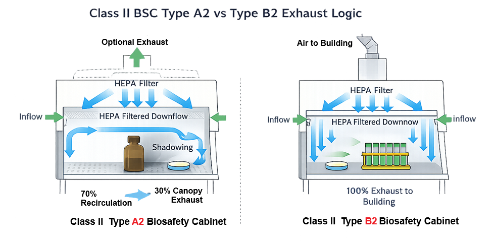
Class II cabinets include several types. Type A2 and Type B2 are emphasized here because they represent materially different recirculating and total-exhaust configurations. Cabinet selection should be based on the applicable edition of NSF/ANSI 49, manufacturer information, process hazards, facility design, and a documented risk assessment.
The illustration below compares the airflow architecture of Type A2 and Type B2 cabinets.
Class II Type A2
A Type A2 BSC recirculates a portion of HEPA-filtered air within the cabinet and exhausts the remaining portion through a HEPA filter. Exhaust may discharge into the room or be connected to the building exhaust through an approved canopy arrangement.
The Type A2 configuration can be suitable for work involving:
- Nonvolatile biological materials
- Particulate hazards
- Aerosol-generating biological manipulations
- Aseptic manipulations requiring both product protection and biological containment
Because cabinet air is recirculated, the use of volatile toxic chemicals or radionuclides is restricted. HEPA filters remove particles but do not remove chemical vapors. Any chemical use must remain within the cabinet manufacturer’s limitations and an approved industrial-hygiene and safety assessment.
A canopy-connected Type A2 cabinet should not be treated as equivalent to a total-exhaust B2 cabinet. The canopy connection is intended to allow cabinet exhaust to be captured while preserving the cabinet’s designed airflow balance.
Class II Type B2
A Type B2 BSC is a total-exhaust cabinet. Air entering the front opening and air supplied to the work zone are exhausted through HEPA filtration to the building exhaust system rather than recirculated within the cabinet.
A Type B2 configuration may be considered when the process requires biological containment together with limited use of volatile toxic chemicals or radionuclides that are necessary to the biological procedure. It is not a general-purpose chemical fume hood.
The design must address:
- Dedicated exhaust capacity
- Duct pressure
- Cabinet-to-exhaust balance
- Exhaust alarms
- Supply and exhaust interlocks
- Failure response
- Safe shutdown
- Room pressure effects
- Filter decontamination and replacement
- Exhaust discharge location
- Energy and heat-load consequences
A failure of the building exhaust can immediately affect cabinet containment and internal airflow. The control strategy should place the cabinet in a defined safe condition and provide a clear alarm to the operator.
Type B2 should not be selected automatically whenever a chemical is present. The quantity, volatility, toxicity, process duration, biological hazard, cabinet compatibility, and facility exhaust design must be evaluated together.
Class II BSC limitations
A BSC does not eliminate process risk. Its performance can be compromised by:
- Rapid arm movements through the front opening
- Blocked front or rear grilles
- Incorrect sash position
- Room drafts
- Nearby doors or personnel traffic
- Excessive equipment loading
- Heat sources
- Improper exhaust connection
- Fan or filter deterioration
- Loss of facility exhaust
- Poor cleaning access
- Unsuitable waste handling
- Unqualified work-zone configurations
The presence of inward airflow also does not establish that every critical site receives suitable first air. Product protection must be evaluated independently from containment.
Risk-Based Equipment Selection
Selection should begin with the hazards and protection objectives of the process, not with a preferred equipment type.
Product and process considerations
The assessment should consider:
- Sterility or cleanliness requirements
- Open-product exposure
- Critical surfaces
- Container size and geometry
- Required equipment and instruments
- Frequency and complexity of manipulations
- Duration of processing
- Potential for spills or splashes
- Heat and turbulence generated by equipment
- Material and waste flows
- Cleaning and disinfection requirements
- Required environmental monitoring
Hazard and containment considerations
The assessment should consider:
- Biological-agent classification
- Toxicity or pharmacological potency
- Sensitization potential
- Aerosol generation
- Powder generation
- Volatile chemical use
- Radionuclide use
- Quantity handled
- Frequency of exposure
- Consequences of operator exposure
- Consequences of release into the room
- Cross-contamination risk
- Spill-response requirements
- Decontamination requirements
A process that requires only product protection may not justify the complexity of a BSC. Conversely, an LFH cannot be justified for a hazardous process merely because it provides acceptable particle cleanliness at the work surface.
Selection matrix
| Process condition | Horizontal LFH | Vertical LFH | Type A2 BSC | Type B2 BSC |
|---|---|---|---|---|
| Product protection only | Potentially suitable | Potentially suitable | Potentially suitable | Usually unnecessary |
| Personnel containment required | Not suitable | Generally not suitable | Potentially suitable | Potentially suitable |
| Biological aerosol risk | Not suitable | Generally not suitable | Common application | Potential application |
| Significant volatile chemical hazard | Not suitable | Not suitable | Generally unsuitable | Requires specific assessment |
| Complex tall equipment | Limited | Potentially suitable | Requires configuration study | Requires configuration study |
| Dependence on building exhaust | Low | Low | Low to moderate, depending on connection | High |
| Total exhaust required | No | No | No | Yes |
“Potentially suitable” means that suitability remains subject to documented assessment, equipment limitations, installation design, certification, and process-specific qualification.
Facility and Exhaust-System Integration
The equipment must be evaluated as part of the room in which it will operate. A cabinet or hood that performs correctly at the factory can fail to provide the intended protection after installation if surrounding airflow or exhaust conditions are unsuitable.
Installation location
Location assessment should consider:
- Doors and airlocks
- Personnel traffic
- Ceiling supply diffusers
- Room return grilles
- Adjacent equipment
- Room pressure relationships
- Cross-drafts
- Space for operator movement
- Cleaning access
- Service and filter-access clearances
- Material staging
- Waste removal
- Emergency access
Door movement, nearby traffic, and ceiling-supply air can disturb the front air barrier of a BSC or disrupt the unidirectional airflow of an LFH.
Exhaust integration
For an exhausted BSC, the design review should establish:
- Exhaust connection type
- Required airflow and static pressure
- Duct materials and routing
- Exhaust fan capacity
- Redundancy, where justified
- Alarm and interlock strategy
- Response to exhaust failure
- Effect on room pressure
- Exhaust discharge location
- Decontamination provisions
- Filter-change strategy
- Maintenance responsibilities
Hard-ducting equipment not designed for that connection can change cabinet airflow and invalidate its certified configuration. Exhaust arrangements should follow the equipment manufacturer’s requirements and applicable technical standards.
Utilities and installed equipment
Utilities introduced into the work zone can obstruct airflow or create contamination risks. Design review should address:
- Electrical receptacles
- Data connections
- Vacuum
- Process gases
- Drain connections
- Tubing penetrations
- Heat-generating equipment
- Balances and analytical instruments
- Waste containers
- Sharps containers
- Sterile transfer devices
Permanent equipment should be represented in the approved work-zone configuration and subsequent qualification studies.
First-Air Protection and Work-Zone Configuration
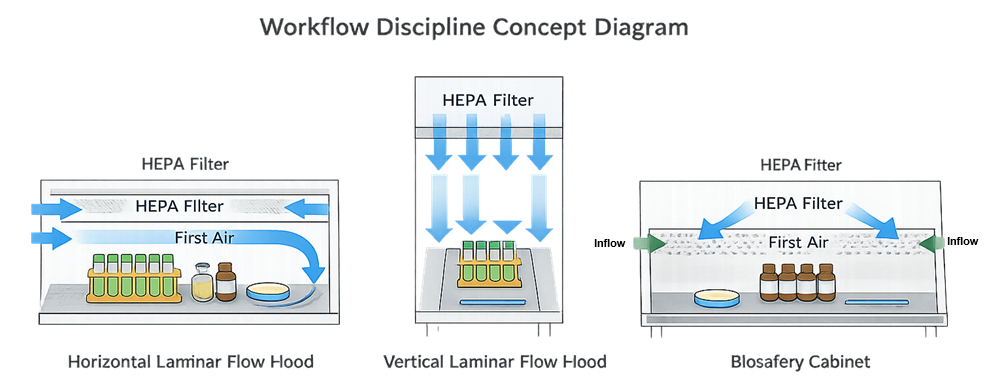
First air is air from the HEPA-filtered source that reaches a critical site without first contacting a potential contamination source. Protecting first air requires deliberate placement of materials, hands, tools, and waste.
The illustration below shows representative staging arrangements for horizontal LFHs, vertical LFHs, and BSCs.
Horizontal LFH staging
In a horizontal LFH:
- Critical sites should be positioned toward the clean-air source.
- Hands and nonsterile items should remain downstream.
- Large objects should not be placed between the HEPA filter and exposed critical sites.
- Materials should progress from cleaner to less clean locations.
- Waste should remain downstream and away from sterile components.
Vertical LFH staging
In a vertical LFH:
- Critical sites should remain beneath unobstructed downflow.
- Materials should be arranged laterally rather than stacked.
- Equipment should not create unacceptable turbulence below the airflow source.
- Return-air grilles should remain clear.
- Operators should avoid reaching over exposed critical sites.
BSC staging
In a BSC:
- Work should be performed sufficiently inside the front opening.
- Front and rear grilles should remain unobstructed.
- Movements through the front opening should be controlled.
- Waste and contaminated items should be segregated from clean materials.
- Equipment should not disrupt the balance between inflow and downflow.
- Open flames should generally be avoided because they disturb airflow and may damage filters or create additional hazards.
The approved configuration should identify the usable work zone, critical sites, equipment positions, material-flow direction, and operator movements. Qualification should challenge that configuration rather than evaluate only an empty cabinet or hood.
Selection and Design-Review Evidence
Before purchase or qualification, the design file should provide evidence that the selected equipment is suitable for its intended use.
Expected evidence may include:
- Approved intended-use statement
- User requirements specification
- Process description
- Product and contamination-risk assessment
- Biological and occupational-hazard assessment
- Required protection functions
- Equipment-type selection rationale
- Airflow and exhaust concept
- Work-zone layout
- Critical-site identification
- Material and waste-flow strategy
- Operator-access requirements
- Cleaning and disinfection requirements
- Construction-material requirements
- Utility requirements
- Alarm and monitoring requirements
- Facility HVAC assessment
- Exhaust-system assessment
- Applicable standards
- Preliminary qualification strategy
- Identified limitations
- Residual risks and procedural controls
The design review should also determine whether a conventional LFH or BSC provides adequate separation for the process. Operations requiring greater physical separation, controlled transfers, or reduced operator access may require a restricted access barrier system or an isolator system instead.
Qualification Interface
Selection and design review establish what subsequent qualification must verify. They do not replace equipment certification or qualification.
Depending on equipment type and intended use, subsequent verification may include:
- Equipment identification and installed configuration
- Location relative to room airflow sources
- Utilities and exhaust connections
- HEPA-filter installation and integrity
- Airflow velocity and uniformity
- BSC inflow and downflow
- Exhaust airflow and duct pressure
- Sash position
- Alarms and interlocks
- Fan and exhaust-failure response
- Particle classification where applicable
- Operational airflow visualization
- Representative equipment loading
- Operator manipulations
- Cleaning and disinfection compatibility
- Recovery or disturbance testing when justified
- Calibration of monitoring instruments
ISO 14644-1 addresses air classification by airborne-particle concentration, but particle classification does not characterize viable contamination or prove that airflow protects a specific aseptic operation. FDA likewise states that ISO 14644 classification standards should not be used alone to demonstrate control of an aseptic-processing environment.
Detailed certification and qualification requirements are addressed in BSC and LFH certification, qualification, and lifecycle control.
Lifecycle and Change Assessment
The original selection and qualification assumptions should remain controlled throughout the equipment lifecycle.
Reassessment may be required following:
- Introduction of a new product or organism
- Increased material potency or toxicity
- New aerosol-generating operations
- Addition of volatile chemicals
- Increased processing scale
- New container or equipment configurations
- Modified work-zone staging
- Addition of heat-generating equipment
- Changes to exhaust connections
- HVAC modification
- Equipment relocation
- HEPA-filter replacement
- Blower or control-system modification
- Changes to cleaning or disinfecting agents
- Changes to waste handling
- Change from product-protection-only use to a containment application
The assessment should determine whether the existing equipment remains suitable, whether procedural changes are sufficient, or whether targeted or comprehensive requalification is required.
Regulatory and Technical Context
For pharmaceutical aseptic processing, the primary U.S. requirements include:
- 21 CFR 211.42, which addresses facility design and aseptic-processing controls, including HEPA-filtered air, environmental monitoring, cleaning, disinfection, and maintenance.
- 21 CFR 211.63, which requires equipment to be appropriately designed, adequately sized, and suitably located for its intended use, cleaning, and maintenance.
- 21 CFR 211.113, which requires procedures to prevent microbiological contamination and validation of aseptic and sterilization processes.
- FDA’s Sterile Drug Products Produced by Aseptic Processing—Current Good Manufacturing Practice, which describes expectations for critical areas, HEPA-filtered airflow, airflow visualization, environmental control, and aseptic operations.
For Class II BSC design and performance, NSF/ANSI 49 provides recognized requirements and field-certification procedures. The CDC/NIH Biosafety in Microbiological and Biomedical Laboratories provides risk-based biosafety guidance but identifies itself as an advisory best-practice document rather than a regulation.
These references serve different purposes. NSF/ANSI 49 certification, ISO particle classification, biosafety assessment, and pharmaceutical qualification provide complementary evidence; none should be treated as a substitute for the others.
Conclusion
Laminar flow hoods and Class II biosafety cabinets are not interchangeable. LFHs primarily provide product protection through HEPA-filtered unidirectional airflow. Class II BSCs combine product protection with inward-airflow containment and HEPA-filtered exhaust for appropriate particulate and biological hazards.
The correct selection depends on intended use, contamination risk, personnel and environmental hazards, process geometry, work-zone configuration, facility airflow, exhaust requirements, and lifecycle controls. ISO 5 particle performance alone does not demonstrate that a unit is suitable for an aseptic or containment application.
A defensible validation strategy begins with documented requirements and a risk-based equipment-selection rationale. Certification and qualification then verify that the selected system, as installed and used, performs the required functions.