

Stoppering, Capping, and Sealing System Qualification
Introduction
Stoppering and capping convert an aseptically filled vial into a closed container-closure system. Although these operations occur near the end of the filling process, they remain critical to sterility assurance, container-closure integrity, particulate control, and product protection.
The elastomeric stopper normally forms the primary sterile seal. The aluminum cap retains the stopper in its intended position and protects the closure during handling, transportation, storage, and administration. Neither component should be evaluated independently of the vial finish, equipment settings, component tolerances, and qualified closure process.
Qualification must therefore demonstrate more than the ability to place stoppers and caps. It should establish that the integrated system consistently:
- Feeds and orients components correctly.
- Places each stopper at the required position.
- Detects missing, displaced, tilted, or improperly seated stoppers.
- Rejects defective units before capping when required.
- Applies the cap without damaging the vial or closure.
- Maintains defined crimping and closure parameters.
- Controls particle generation.
- Preserves the required environmental protection.
- Produces closure assemblies capable of meeting the established container-closure integrity requirements.
The qualification strategy should be integrated with the broader aseptic filling line architecture and fill line qualification lifecycle.
Understanding the vial closure system
A vial closure system is a combination of interacting components rather than a collection of independent parts. Its performance depends on the dimensional and material relationships among:
- The vial finish and neck geometry.
- The elastomeric stopper flange and plug.
- Stopper elastomer formulation, coating, hardness, and compression behavior.
- The aluminum seal and plastic flip-off button, when present.
- Stopper insertion depth.
- Cap compression and crimp formation.
- Dimensional tolerances accumulated across all components.
The stopper plug creates contact against the internal surface of the vial neck. The stopper flange is compressed between the vial finish and cap. The cap then maintains the stopper’s position by forming its skirt beneath the vial bead.
A visually acceptable closure does not necessarily have adequate integrity. Conversely, an unusual cosmetic appearance does not automatically establish a loss of integrity. Visual inspection, dimensional testing, equipment parameters, and Container Closure Integrity Testing (CCIT) provide different types of evidence and should be interpreted within a predefined control strategy.
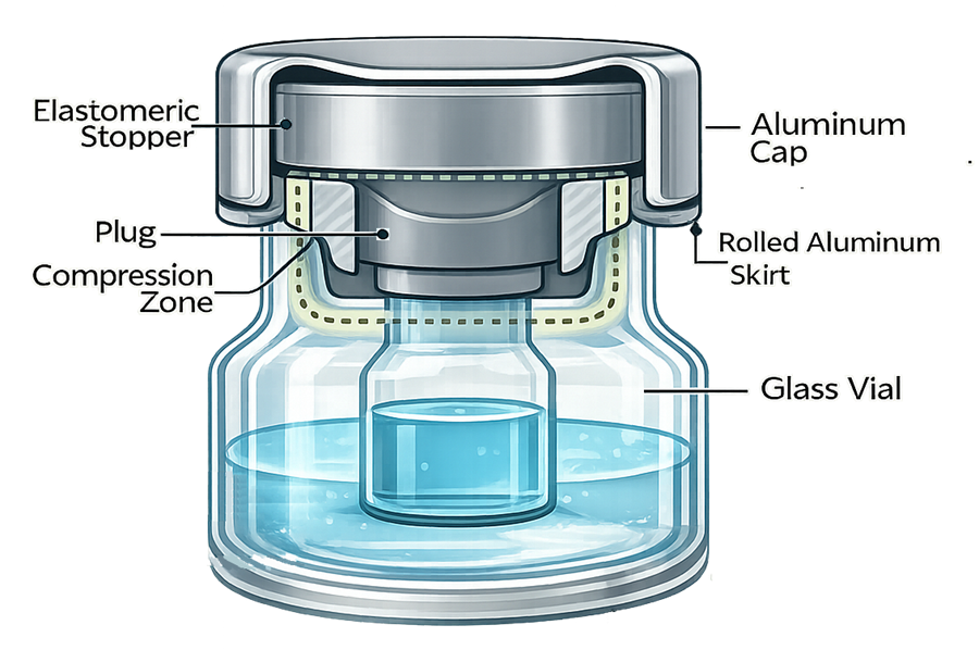
Stoppering system design and function
Stopper preparation and delivery
Before reaching the filling line, stoppers are normally washed, sterilized, protected, and transferred using qualified processes. These activities should be covered by the qualification of sterile component preparation and transfer.
The stoppering equipment boundary may include:
- Stopper transfer containers or bags.
- Transfer ports and docking devices.
- Stopper hoppers or replenishment systems.
- Feed bowls, tracks, chutes, and orientation devices.
- Sensors for component presence and feed status.
- Placement tubes, pick-and-place devices, or insertion mechanisms.
- Stopper-height or position-detection systems.
- Vial tracking and reject mechanisms.
- Associated controls, recipes, alarms, and electronic records.
Surfaces that contact sterile stoppers or could directly affect their sterile state should have defined cleaning, sterilization, assembly, storage, and hold-time requirements.
Full stoppering
For liquid-filled vials, the stopper is generally inserted to its final position on the filling line. Qualification should demonstrate consistent placement without stopper inversion, tilting, rebound, extrusion, or unacceptable damage.
Important variables may include:
- Stopper presentation and orientation.
- Vial centering beneath the stoppering mechanism.
- Insertion depth, position, or force.
- Machine speed and acceleration.
- Stopper and vial dimensional tolerances.
- Elastomer properties and surface treatment.
- Equipment vibration.
- Stopper-track loading and replenishment.
- Environmental temperature and humidity, where relevant.
The parameters requiring formal control should be selected through documented risk assessment and process-development evidence. Insertion force alone should not automatically be classified as a critical process parameter unless it is measured, controlled, and shown to affect closure quality.
Partial stoppering for lyophilized products
Vials intended for lyophilization are partially stoppered before transfer to the lyophilizer. The stopper must remain high enough to allow vapor flow while remaining stable during transport, loading, and the lyophilization cycle.
Final stoppering normally occurs inside the lyophilizer. Qualification must therefore cover the complete interface among:
- Partial stopper placement.
- Vial transfer and accumulation.
- Lyophilizer loading.
- Shelf movement and final stopper seating.
- Unloading and transfer to the capper.
- Protection of fully stoppered but uncapped vials.
This integrated system is addressed further in qualification of the lyophilization–aseptic filling interface.
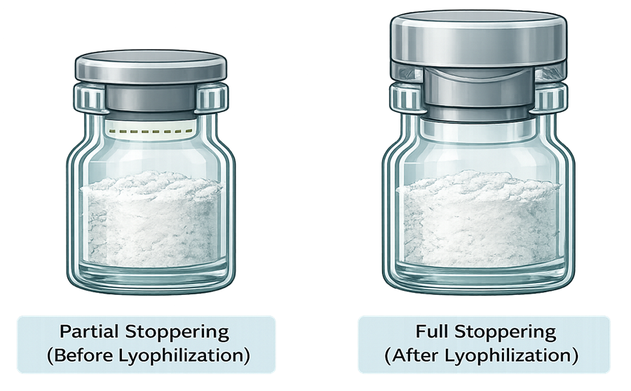
Capping and crimping system design
Role of the cap
The cap does not normally create the original sterile boundary. That boundary is established when the sterile stopper is correctly seated in the vial. The cap applies and maintains mechanical retention of the stopper.
Capping should nevertheless be treated as a critical finishing operation because an unsuitable crimp can:
- Reduce stopper retention.
- Distort the elastomer.
- Damage the vial finish.
- Produce metal or glass particles.
- Interfere with inspection or administration.
- Contribute to loss of container-closure integrity.
Cap preparation requirements depend on the capping strategy. Capping may be performed as an aseptic process using sterilized caps or as a controlled clean process after stoppering. It is therefore incorrect to state that caps must always be sterile.
Environmental protection before crimping
Stoppered but uncapped vials require protection appropriate to the process design and contamination control strategy.
FDA recommends suitable local protection when stoppered vials leave the aseptic processing zone before completion of crimping. FDA also identifies online detection of improperly seated stoppers as an additional assurance measure. See the FDA Guidance for Industry: Sterile Drug Products Produced by Aseptic Processing.
EU GMP Annex 1 provides more prescriptive expectations. It permits capping either as an aseptic process using sterilized caps or as a clean process outside the aseptic processing area. When the clean-process approach is used, stoppered vials are expected to remain protected by Grade A air supply until crimping. Annex 1 also calls for appropriately qualified automated stopper-height detection and rejection of vials with missing or displaced stoppers before capping. See EU GMP Annex 1, paragraphs 8.26–8.29.
The selected approach should be defined in the contamination control strategy and supported by qualified airflow visualization studies and the following controls:
- Airflow visualization.
- Environmental qualification and monitoring.
- Intervention assessment.
- Stopper-height detection.
- Vial transfer studies.
- Particle-control measures.
- Equipment and process qualification.
Relevant barrier controls should be coordinated with the qualification of the applicable RABS or isolator system.
Crimping operation
Common capping systems use rotary, roll-on, or other mechanically controlled crimping mechanisms. Depending on the equipment design, significant variables may include:
- Capping-head position.
- Compression plate or plunger setting.
- Crimp roller position.
- Applied force or pressure.
- Vial lift height.
- Head rotation or dwell time.
- Machine speed.
- Cap and vial alignment.
- Tool wear.
- Cap-feed condition.
- Vial and closure tolerances.
Qualification should establish an acceptable operating range rather than relying on one nominal machine setting. The range should account for representative combinations of vials, stoppers, and caps.
Component tolerances and equipment settings
Every closure component has dimensional variability. Vial height and finish geometry, stopper thickness, flange dimensions, cap dimensions, and aluminum thickness can combine to produce a total tolerance greater than the variation of any individual component.
Consequently, a capping setting established with nominal components may perform differently when components approach their approved dimensional limits.
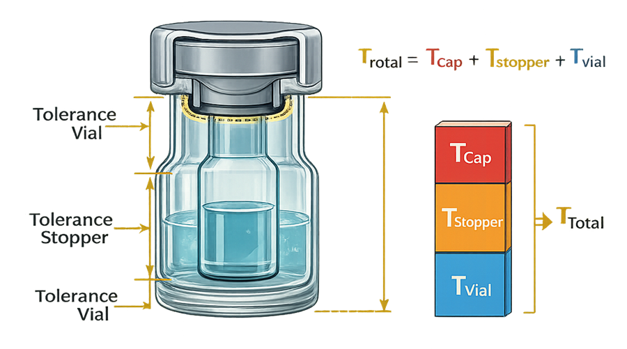
Tolerance evaluation should consider:
- Approved supplier specifications.
- Incoming inspection data.
- Multiple component lots.
- Dimensional extremes.
- Equipment adjustment capability.
- Measurement uncertainty.
- Relationships between dimensions, crimp appearance, stopper compression, and CCIT.
Where bracketing or matrixing is used, the rationale should identify the attributes that actually create the worst-case condition. The largest vial, highest speed, or maximum compression setting is not automatically the worst case.
Qualification strategy
User requirements and system boundaries
The user requirements specification should describe what the stoppering and capping system must accomplish and how satisfactory performance will be demonstrated.
Requirements should address, as applicable:
- Container and closure families.
- Full and partial stoppering.
- Intended operating-speed range.
- Stopper and cap feed capacity.
- Stopper-height detection.
- Cap-presence and orientation detection.
- Container tracking.
- Defect rejection and reconciliation.
- Crimping adjustment and control.
- Particle extraction.
- Environmental and barrier interfaces.
- Permitted interventions.
- Recipe and access control.
- Alarm and event recording.
- Electronic data retention.
- Cleaning and sterilization requirements.
- Change-part control.
- Maintenance and calibration.
The system boundary should include upstream and downstream interfaces when their operation can influence stoppering, capping, contamination control, rejection, or closure quality.
Design qualification
Design qualification should verify that the selected equipment and configuration can meet the approved requirements and support the contamination control strategy.
The review should evaluate:
- Component flow and orientation.
- Accessibility for cleaning, setup, and maintenance.
- Prevention of component mix-ups.
- Protection of sterile stoppers.
- Location of particle-generating operations.
- Air extraction around the capper.
- Impact on unidirectional airflow.
- Intervention frequency and ergonomics.
- Stopper-height and cap-detection technology.
- Reject segregation and container tracking.
- Change-part identification.
- Control-system architecture.
- Data integrity and audit-trail requirements.
Where crimping can generate substantial nonviable particles, EU GMP Annex 1 identifies physical separation and adequate extraction as possible preventive measures. The installed design should be supported by appropriate particle and airflow studies.
Installation qualification
Installation qualification should verify, as applicable:
- Equipment identity and configuration.
- Stopper and cap feeding assemblies.
- Crimping heads and tooling.
- Product-contact and component-contact materials.
- Format and change parts.
- Sensors, cameras, encoders, and reject devices.
- Guards, barriers, extraction, and local airflow protection.
- Electrical, pneumatic, vacuum, and extraction utilities.
- Instrument calibration status.
- Motor, drive, and control-panel installation.
- Software and firmware versions.
- Approved drawings and manuals.
- Spare-part and preventive-maintenance requirements.
Discrepancies should be resolved or formally assessed before operational qualification proceeds.
Operational qualification
Operational qualification should challenge the equipment throughout its approved operating ranges.
Stoppering challenges
Testing should include representative challenges such as:
- Minimum and maximum qualified speeds.
- Low and high stopper-feed conditions.
- Full and partial stopper insertion.
- Missing stopper.
- Inverted or incorrectly oriented stopper.
- Tilted or incompletely seated stopper.
- Stopper rebound.
- Stopper-track jam.
- Empty stopper-feed condition.
- Sensor misalignment or failure.
- Defined stopper-height limits.
- Restart after an interruption.
Stopper-height detection should be challenged around the established acceptance boundary, not only with obvious defects. Challenge standards should be identified, controlled, and periodically verified.
Capping and crimping challenges
Testing should address:
- Approved capping-head settings.
- Minimum and maximum qualified speeds.
- Cap absence or incorrect orientation.
- Missing or displaced stopper before capping.
- Under-crimp and over-crimp conditions.
- Crimping-head misalignment.
- Worn or damaged tooling.
- Cap-feed interruption.
- Vial jam.
- Loss of extraction.
- Container breakage.
- Restart following a stoppage.
Acceptance criteria should distinguish equipment responses, dimensional results, cosmetic defects, and integrity-related evidence.
Detection, tracking, and rejection
A defect-detection system is only effective when the identified container is reliably removed.
Qualification should demonstrate:
- Detection of the intended defect.
- Association of the signal with the correct container.
- Tracking through accumulation and transfer sections.
- Activation of the reject mechanism.
- Physical removal of the defective unit.
- Confirmation of rejection.
- Alarm generation when rejection fails.
- Security and reconciliation of rejected units.
- Response to a full or unavailable reject bin.
Challenges should be conducted at representative speeds and accumulation conditions.
Automation and electronic records
Computerized functions affecting closure quality should be included in the qualification scope. Testing should address:
- Recipe creation and approval.
- Parameter limits.
- User access and role permissions.
- Unauthorized parameter changes.
- Audit trails.
- Alarm and event history.
- Manual and bypass modes.
- Sensor overrides.
- Data transfer to supervisory systems.
- Backup and restoration.
- Time synchronization.
- Power-loss recovery.
The scope should be aligned with 21 CFR 211.68 and the site’s Part 11 compliance strategy.
Performance qualification
Performance qualification should demonstrate reproducible operation using representative production conditions, trained operators, approved procedures, and production-equivalent components.
PQ selection should consider:
- Vial sizes and finish geometries.
- Stopper formulations, coatings, and dimensions.
- Cap configurations and aluminum thicknesses.
- Full and partial stoppering.
- Liquid and lyophilized presentations.
- Operating speeds.
- Batch duration.
- Component replenishment.
- Changeover and startup conditions.
- Multiple component lots.
- Routine interventions.
- Operation near justified process limits.
PQ should confirm consistent equipment and process performance. It does not replace:
- Container-closure integrity method validation.
- Product-specific CCIT studies.
- Aseptic process simulation.
- Sterilization validation for stoppers or equipment.
- Visual inspection process qualification.
Mechanical defects and failure challenges
Qualification should use controlled defect standards representative of realistic failure mechanisms. Artificial defects should be documented and shown to be suitable for the intended challenge. Common stoppering and capping defects include:
- Missing stopper.
- High stopper.
- Tilted stopper.
- Inverted stopper.
- Stopper extrusion.
- Missing or misoriented cap.
- Under-crimp.
- Over-crimp.
- Incomplete or asymmetric skirt roll.
- Cap rotation.
- Skirt cracking.
- Stopper or cap damage.
- Cracked vial finish.
- Chipped glass.
- Metal or glass particles.
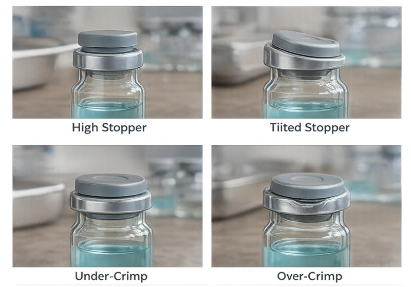
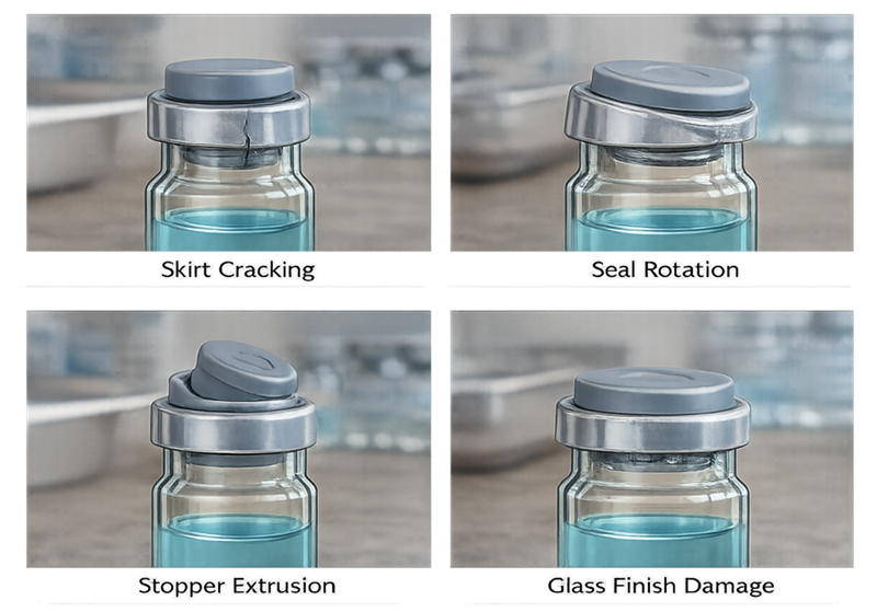
These two illustrations should remain together because they form one visual defect library. They should not be separated by additional article text.
Detection studies should document:
- Defect identity and construction.
- Defect severity or measured dimension.
- Challenge location.
- Equipment speed.
- Number of presentations.
- Number detected and rejected.
- False-reject observations.
- Challenge-set traceability.
- Post-study reconciliation.
Challenge units should be controlled to prevent accidental entry into commercial product.
Relationship to container-closure integrity testing
Equipment qualification and CCIT answer related but different questions.
Stoppering and capping qualification demonstrates that the equipment operates reproducibly, detects defined failures, controls critical settings, and consistently assembles the closure.
Container-closure integrity testing determines whether the assembled container-closure system maintains the required barrier against potential ingress or product loss.
Crimp diameter, residual seal force, stopper height, torque, visual appearance, and compression measurements can support process understanding and routine control. However, none should automatically be treated as a direct substitute for a validated integrity test.
The validation strategy should establish scientifically justified relationships among:
- Component specifications.
- Equipment operating ranges.
- Closure dimensions.
- Mechanical measurements.
- Defect types.
- Product and process conditions.
- CCIT results.
- Storage and transportation challenges.
FDA’s Container Closure Systems for Packaging Human Drugs and Biologics provides the broader regulatory framework for evaluating container-closure suitability and protection.
Integration with aseptic process simulation
Stoppering activities that occur within the aseptic processing boundary should be represented in the aseptic process simulation program.
Applicable interventions may include:
- Stopper replenishment.
- Clearing a stopper-track jam.
- Adjustment or replacement of a stoppering component.
- Removal of fallen or tipped vials.
- Stopper-height detector intervention.
- Cleaning following breakage.
- Transfer of partially stoppered vials.
- Lyophilizer loading and unloading.
- Restart after an extended stoppage.
The simulation should reproduce the intervention technique, duration, frequency, personnel involvement, and post-intervention clearance applied during commercial production.
Capping activities conducted outside the aseptic boundary should not automatically be treated as aseptic interventions. Their inclusion should depend on the defined process boundary and documented contamination risk.
Routine operation and batch review
Before operation, personnel should verify:
- Correct vial, stopper, and cap components.
- Approved sterilization or preparation status.
- Correct format parts and tooling.
- Approved recipe.
- Equipment setup and line clearance.
- Sensor and reject-system challenge results.
- Calibration status.
- Barrier and airflow status.
- Extraction availability.
- Stopper-height and cap-detection readiness.
Batch review should evaluate:
- Critical equipment settings.
- Stopper and cap reconciliation.
- Alarms and events.
- Reject quantities and classifications.
- Stopper-height and crimp measurements.
- Equipment adjustments.
- Jams and interventions.
- Vial breakage.
- Extraction interruptions.
- Deviations and unexplained discrepancies.
- Relevant inspection or CCIT results.
The review should distinguish routine process rejects from signals of declining control. Repeated defects below an individual action limit may still require investigation when an adverse trend is present.
Failure response and product impact assessment
A predefined response should exist for failures capable of affecting units already processed.
Examples include:
- Stopper-height detector failure.
- Reject-system failure.
- Loss of container tracking.
- Incorrect capping recipe.
- Crimping-head damage.
- Loss of particle extraction.
- Discovery of a damaged change part.
- Abnormal reject trend.
- Power loss or uncontrolled restart.
- Barrier or local airflow failure.
The response should establish:
- When processing must stop.
- Which units must be segregated.
- How the potentially affected time window is determined.
- Whether physical inspection, dimensional testing, or CCIT is required.
- How rejected and retained units are reconciled.
- How sterility and particulate risks are assessed.
- Who approves restart and product disposition.
Successfully repeating a detector challenge or measurement does not erase the original failure. The investigation must determine when control was lost and what product may have been affected.
Continued process verification
Continued verification should confirm that the qualified system remains within its validated state.
Useful indicators include:
- Stopper-height distributions.
- Crimp dimensions.
- Equipment reject rates.
- Defect categories.
- Stopper and cap feed interruptions.
- Jam and intervention frequency.
- Capping-head adjustments.
- Tool wear and replacement.
- Vial breakage.
- Particle and extraction performance.
- Detection-system challenge results.
- Alarm frequency.
- Maintenance and calibration history.
- CCIT results and trends.
- Relevant aseptic filling environmental monitoring results and trends.
- APS observations and intervention history.
Trends should be reviewed across batches, component lots, products, shifts, and equipment heads when those distinctions could reveal localized deterioration.
Change control and requalification
Changes affecting stoppering, capping, or closure performance should undergo documented impact assessment.
Potential requalification triggers include:
- New vial, stopper, or cap.
- New component supplier or manufacturing site.
- Change in elastomer formulation, coating, hardness, or lubrication.
- Change in vial finish or dimensional specification.
- Change in cap thickness or geometry.
- Addition of a new container size.
- Increased line speed.
- Replacement or redesign of stoppering or capping equipment.
- Modification of feed bowls, tracks, transfer paths, or tooling.
- New stopper-height, cap-detection, or vision system.
- Control-system or recipe change.
- Barrier, airflow, or extraction modification.
- Change to lyophilizer loading or final stoppering.
- Major repair or prolonged shutdown.
- Adverse defect, maintenance, or CCIT trend.
The extent of requalification should be proportionate to the risk and supported by the site’s change-control impact assessment and risk-based requalification program.
Common qualification deficiencies
Common weaknesses include:
- Treating capping as a cosmetic packaging operation.
- Failing to define the system boundary.
- Qualifying only nominal machine settings.
- Assuming maximum speed is always the worst case.
- Using only one component lot.
- Failing to challenge stopper-height detection near the acceptance limit.
- Demonstrating detection without confirming physical rejection.
- Inadequate container tracking through accumulation sections.
- Treating crimp dimensions as proof of container-closure integrity.
- Excluding particle extraction from qualification.
- Inadequate evaluation of stoppered but uncapped vial protection.
- Failing to include relevant stoppering interventions in APS (Aseptic Process Simulation).
- Uncontrolled challenge samples or defect standards.
- Insufficient linkage among qualification, visual inspection, and CCIT.
- Requalification based only on elapsed time rather than system performance and change.
Conclusion
Stoppering and vial capping qualification should demonstrate control of the complete closure-assembly process—from sterile stopper delivery through placement, detection, crimping, rejection, inspection, and lifecycle monitoring.
A strong qualification program does not rely on a single crimp dimension or visual attribute. It combines equipment qualification, component knowledge, defect challenges, environmental protection, automated detection, reliable rejection, continued verification, and validated CCIT.
When these elements are integrated, the stoppering and capping system provides documented assurance that closure assemblies are produced consistently and remain suitable for protecting sterile product throughout its intended lifecycle.