

Restricted Access Barrier Systems: Design and Qualification
Restricted access barrier systems reduce the direct interaction between operators and exposed sterile product by enclosing critical processing operations behind rigid barriers and providing access through glove ports, transfer devices, and controlled interventions.
A RABS is more than a filling line surrounded by panels. Its protective performance depends on the integrated design of:
- The aseptic processing equipment
- The barrier enclosure
- HEPA-filtered unidirectional airflow
- First-air protection
- Return-air pathways
- The supporting cleanroom
- Glove and sleeve assemblies
- Material-transfer systems
- Cleaning and disinfection controls
- Intervention procedures
- Environmental monitoring
- Automation and alarms
Qualification must demonstrate that these elements operate together under representative production conditions. Particle classification or HEPA-filter integrity testing alone cannot establish that the RABS protects exposed sterile product during setup, filling, interventions, component replenishment, line stoppages, and material transfers.
This article addresses RABS design, qualification, process integration, release, and lifecycle control. Detailed barrier-glove qualification, barrier-system bio-decontamination validation, and aseptic process simulation are addressed separately.
Intended Use and System Boundaries
The intended use establishes what the RABS must protect, how it will be operated, and which functions require qualification.
The intended-use definition should identify:
- Product and dosage form
- Container and closure system
- Filling and closing operations
- Exposed sterile product, components, and critical surfaces
- Required processing speed and duration
- Batch and campaign strategy
- Open or closed RABS configuration
- Background cleanroom classification
- Product-protection and containment requirements
- Filling-line equipment enclosed by the barrier
- Component and material-transfer methods
- Product-pathway boundaries
- Required glove-port interventions
- Planned door-opening conditions
- Cleaning and disinfection strategy
- Sterilization of product-contact equipment
- Environmental-monitoring requirements
- Automation and control-system interfaces
- Lyophilizer or other connected-equipment interfaces
- Required maintenance access
The system boundary should include all equipment and facility elements capable of affecting the critical zone. Depending on the design, this may include:
- Rigid wall panels and viewing windows
- Access doors and seals
- Glove ports, sleeves, and gauntlets
- HEPA-filter housings
- Supply fans or facility HVAC supply
- Air-return pathways
- Pressure and airflow instruments
- Filling and stoppering equipment
- Container and closure feeding systems
- Transfer ports
- Mouseholes and conveyor openings
- Reject stations
- Environmental-monitoring devices
- Lighting and internal utilities
- Controls, alarms, interlocks, and electronic records
- Supporting cleanroom and HVAC interfaces
A boundary that includes only the physical enclosure is inadequate because the RABS cannot perform independently of its airflow source, filling equipment, transfers, interventions, and supporting environment.
RABS Architecture
A typical RABS places a rigid physical barrier between operators and an aseptic filling line. Operators perform routine manipulations through glove ports rather than reaching directly into the critical zone.
The photograph below shows a representative RABS integrated with an aseptic filling line.
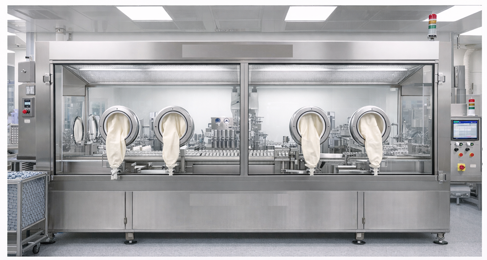
Principal architectural elements include:
- Rigid enclosure panels
- Transparent viewing windows
- Glove and sleeve assemblies
- Controlled access doors
- HEPA-filtered airflow
- Return-air grilles
- Product and component infeed
- Container outfeed
- Transfer ports or transfer openings
- Environmental-monitoring locations
- Filling-line controls and alarms
The barrier reduces direct operator access, but it does not eliminate operator influence. Glove manipulation, material transfer, door opening, maintenance, and adjacent personnel movement can still disturb airflow or introduce contamination.
The enclosure should therefore support observation, intervention, cleaning, disinfection, maintenance, and environmental monitoring without compromising the critical zone.
Critical Zone and Local Protection
The critical zone is the area in which exposed sterile product, sterile components, container closures, or critical surfaces require the highest level of protection. Within a RABS, the critical zone normally includes locations such as:
- Filling needles
- Open containers
- Sterile product-contact connections
- Stopper bowls and tracks
- Stopper-placement locations
- Partially stoppered containers
- Exposed sterile tools
- Critical transfer points
- Open-container paths to connected equipment
Not every part of the enclosure presents the same risk. Qualification should identify the local protection zones associated with critical sites and demonstrate that appropriate first air is maintained at those locations.
The diagram below illustrates the relationship among the HEPA supply, barrier panels, glove ports, return-air grilles, filling equipment, critical processing area, and supporting cleanroom.
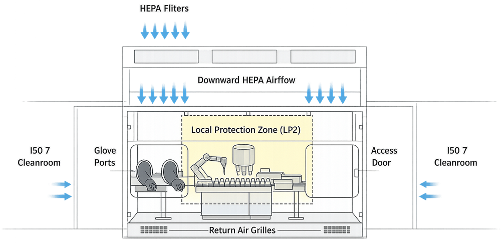
The local protection zone shown in the diagram should be interpreted as the defined area requiring direct, unobstructed airflow protection. Its extent must be established from the actual product-exposure points and processing configuration rather than assumed to include the entire enclosure.
Open and Closed RABS
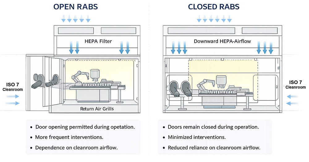
Open and closed RABS both use barriers, restricted access, and controlled airflow to protect the critical processing zone. Both are intended to operate with doors closed during normal aseptic processing.
The distinction concerns the enclosure and airflow architecture, the degree of separation from the supporting room, and how exceptional access and air return are managed. Door opening should not be treated as the sole design distinction.
The illustration below presents the general comparison. Its statement that door opening is permitted for an open RABS must be read as referring only to rare, predefined, documented interventions—not routine access during production.
Open RABS
An open RABS typically allows HEPA-filtered air from the critical zone to discharge partly into the surrounding cleanroom through defined openings or through the lower portion of the enclosure. Its airflow design maintains outward airflow from the protected zone and limits ingress from the supporting room.
An open RABS should normally remain closed during aseptic processing. Under rare, predefined conditions, a door may be opened to perform an intervention that cannot be completed through a glove port or other controlled interface.
Such an intervention requires:
- Prior definition and risk assessment
- Documented justification
- Trained and qualified personnel
- Defined product-clearance requirements
- Control of nearby exposed containers
- Appropriate disinfection
- Environmental-monitoring consideration
- Batch-record documentation
- Representation in airflow studies
- Representation in aseptic process simulation where applicable
- Assessment before routine processing resumes
If doors are routinely opened during production, the system no longer provides the restricted-access control expected of a RABS.
Closed RABS
A closed RABS maintains a more contained internal airflow pathway during operation. Air is typically returned through dedicated ducts or recirculation pathways rather than being discharged freely into the supporting room.
Access doors remain closed throughout aseptic processing. Interventions are performed through glove ports, automation, or other closed interfaces.
A closed RABS can provide:
- Greater separation from personnel
- More controlled internal airflow
- Reduced interaction with room disturbances
- Improved control of interventions
- More defined pressure and return-air behavior
It remains dependent on the supporting cleanroom, validated surface-control practices, component-transfer controls, glove integrity, and operator discipline. A closed RABS is not equivalent to an isolator and should not be described as a sterile enclosure.
Comparison of open and closed RABS
| Attribute | Open RABS | Closed RABS |
|---|---|---|
| Normal door condition during processing | Closed | Closed |
| Exceptional door opening | May be permitted under rare, predefined, controlled conditions | Not normally permitted during processing |
| Air return | May discharge partly to the supporting room | More commonly uses defined internal or ducted return |
| Dependence on background cleanroom | High | High, although room interaction may be reduced |
| Routine interventions | Through glove ports or controlled interfaces | Through glove ports or controlled interfaces |
| Surface treatment | Validated cleaning and disinfection or bio-decontamination strategy | Validated cleaning and disinfection or bio-decontamination strategy |
| Automated enclosure bio-decontamination | Not inherent to the RABS definition | Not inherent to the RABS definition |
| Separation from operators | Improved over open cleanroom processing | Generally greater than open RABS |
| Qualification emphasis | Air ingress, door-opening risks, room interaction | Internal airflow, closed-state control, glove and transfer integrity |
Actual design features vary. The system should be classified and qualified according to its installed architecture and approved operating model rather than its vendor label alone.
RABS and Isolators
RABS and isolators are different barrier technologies. A RABS normally:
- Operates within a highly controlled supporting cleanroom
- Uses unidirectional airflow over critical sites
- Depends substantially on room cleanliness and HVAC performance
- Uses glove ports to restrict operator access
- Relies on validated cleaning and disinfection
- May use manual or automated surface bio-decontamination
- Does not inherently provide a sealed, automatically bio-decontaminated enclosure
An isolator system normally provides a higher degree of physical separation and uses an integrated, reproducible bio-decontamination process for the enclosure. Its supporting-room requirements may differ based on design and risk assessment.
Neither technology eliminates the need for:
- Sterilization of product-contact equipment
- Controlled material transfer
- Glove-integrity control
- Airflow qualification
- Environmental monitoring
- Aseptic process simulation
- Maintenance
- Change control
- Requalification
RABS selection should be justified from the process, intervention burden, background environment, transfer requirements, cleaning strategy, and desired degree of operator separation.
Airflow Design and First-Air Protection
A RABS used for aseptic filling should provide HEPA-filtered airflow that protects exposed sterile product and critical surfaces. The airflow system may be:
- Integrated with ceiling-mounted facility HEPA filters
- Supplied by dedicated fan-filter units
- Partially recirculating
- Connected to dedicated return or exhaust pathways
- Configured to provide product protection together with containment where justified
The airflow design should establish:
- Required air quality
- Airflow direction
- Airflow velocity or volume
- Uniformity criteria
- HEPA-filter coverage
- Critical-zone boundaries
- First-air pathways
- Return-air locations
- Pressure relationships
- Monitoring locations
- Alarm limits
- Response to airflow loss
A single average airflow velocity is not sufficient to demonstrate protection. The actual airflow pattern must be evaluated around equipment, glove ports, transfer openings, doors, conveyors, sensors, and environmental-monitoring devices.
First-air protection
First air is HEPA-filtered air that reaches a critical site before contacting a potential contamination source. Potential obstructions include:
- Filling-machine structures
- Stopper bowls and tracks
- Tubing and manifolds
- Operator gloves and sleeves
- Environmental-monitoring equipment
- Transfer bags
- Tools
- Reject devices
- Guards
- Permanently installed instruments
Qualification should demonstrate that first air remains effective during:
- Initial setup
- Routine filling
- Component replenishment
- Glove manipulations
- Routine interventions
- Non-routine interventions
- Line stoppages
- Container removal
- Cleaning or adjustment activities represented during processing
- Transfer to connected equipment
Return-air pathways
Return-air grilles and low-level returns should be positioned so that contaminated air is removed without drawing lower-quality air across critical sites. The design should prevent:
- Blocked return grilles
- Air recirculation near exposed product
- Reverse flow at transfer openings
- Stagnant regions
- Uncontrolled entrainment from the supporting room
- Airflow returning from the operator side toward critical sites
Equipment, temporary materials, carts, and operator activities should not obstruct qualified return-air pathways.
Pressure and Background Environment
A RABS does not operate independently of its supporting cleanroom. The background environment supports the barrier through:
- Air cleanliness
- Pressure control
- Temperature and humidity control
- Personnel gowning
- Cleaning and disinfection
- Material-transfer controls
- Environmental monitoring
- HVAC recovery and alarm response
For U.S. aseptic-processing applications, the critical zone is normally controlled as ISO 5, while the appropriate supporting environment is determined from the process and barrier design. FDA guidance generally describes an ISO 7 area immediately adjacent to an ISO 5 critical area for conventional aseptic processing unless an alternative provides equivalent or greater protection.
EU GMP Annex 1 uses Grade A terminology for the RABS critical zone and requires at least a Grade B background for RABS used in aseptic processing.
These designations should not be treated as interchangeable labels without considering their different regulatory frameworks, occupancy states, viable-monitoring expectations, and operational controls. The relationship between ISO classes and EU grades is addressed in Cleanroom Classification and ISO Grades.
Pressure and airflow should support movement from the protected critical zone toward the background unless a justified containment strategy requires an alternative design. Product protection and containment requirements must be reconciled through documented risk assessment and qualification.
Barrier Panels, Doors, and Seals
Barrier panels and doors establish the physical separation between personnel and the critical processing area. Design review should address:
- Panel materials
- Surface finish
- Cleanability
- Chemical resistance
- Viewing quality
- Mechanical rigidity
- Joint design
- Door seals
- Gaskets
- Latches
- Hinges
- Penetrations
- Glove-port attachment
- Maintenance access
Gaps, damaged seals, poorly fitted panels, or unsealed penetrations can allow uncontrolled airflow or make effective cleaning difficult. Door design should include:
- Defined access purpose
- Open and closed status indication
- Alarm or interlock where justified
- Controlled opening sequence
- Access authorization
- Documentation requirements
- Post-opening disinfection requirements
- Restart conditions
- Product-clearance requirements
Door status should be available to the operating and batch-record system when it is a critical process parameter or intervention record.
Glove and Sleeve Systems
Glove assemblies are critical components because they allow operator manipulation inside the critical zone while maintaining physical separation.
The system includes:
- Glove
- Sleeve or gauntlet
- Glove port
- Retaining rings
- Seals
- Attachment hardware
- Integrity-test interface
Design and qualification should address:
- Material compatibility
- Reach and ergonomics
- Mechanical durability
- Chemical resistance
- Sterilization or bio-decontamination compatibility
- Port location
- Replacement method
- Visual inspection
- Integrity testing
- Failure response
- Service-life management
Glove-port placement should allow required interventions without:
- Excessive stretching
- Contact with critical surfaces
- Blocking first air
- Contact between sleeves and equipment
- Uncontrolled movement over open containers
- Unsafe operator posture
Detailed requirements are addressed in Barrier Glove Integrity Qualification and Lifecycle Control.
Material and Component Transfer
Material transfer is a major contamination-control challenge because components must pass from the supporting environment into the critical zone without compromising protection.
Transfer methods may include:
- Double-door sterilizer interfaces
- Depyrogenation-tunnel interfaces
- Rapid transfer ports
- Pass-through chambers
- Bagged sterile components
- Surface-disinfected transfer items
- Continuous component-feed systems
- Conveyor openings
- Mouseholes
- Closed sterile connections
The transfer strategy should define:
- Item preparation
- Sterilization or depyrogenation status
- Packaging configuration
- Outer-wrap removal
- Disinfection method
- Contact time
- Transfer sequence
- Door and port operation
- Maximum opening duration
- Operator actions
- Environmental monitoring
- Product-clearance requirements
- Response to dropped or damaged items
Transfer ports and openings should be included in airflow visualization studies. The studies should demonstrate that transfer does not cause unacceptable air ingress, reverse flow, or loss of first-air protection.
The preparation and protection of components before presentation to the RABS are addressed in Sterile Component Preparation and Transfer.
Intervention Control
The value of a RABS depends substantially on reducing direct interventions into the critical zone. The process should maintain an approved intervention inventory covering:
- Inherent interventions
- Routine interventions
- Corrective interventions
- Non-routine interventions
- Door-opening interventions
- Maintenance interventions
Each intervention should define:
- Reason for intervention
- Required tools
- Access point
- Operator position
- Glove ports used
- Sequence of actions
- Duration
- Containers or critical sites affected
- Required product clearance
- Disinfection requirements
- Environmental-monitoring considerations
- Batch-record documentation
- Airflow-study representation
- APS representation
Design improvements should be considered when intervention data show recurring manual activity. Possible improvements include:
- Automated component replenishment
- Improved container handling
- Automatic reject systems
- Remote adjustments
- Additional glove ports
- Redesigned tools
- Better access
- Improved sensors
- Elimination of recurring jams
- Robotic manipulation
The qualification program should not normalize a poorly designed, intervention-intensive process merely by simulating it repeatedly.
Cleaning, Disinfection, and Surface Control
RABS internal surfaces require a validated cleaning and disinfection program.
Cleaning removes product residue, visible soil, and other materials that may interfere with disinfection. Disinfection reduces microbial contamination. A sporicidal treatment may be required according to the approved contamination-control strategy.
The program should define:
- Cleaning agents
- Disinfectants
- Sporicidal agents
- Concentrations
- Preparation and expiry
- Application methods
- Wet contact times
- Sequence of use
- Coverage
- Drying requirements
- Residue removal
- Material compatibility
- Frequencies
- Responsibilities
- Documentation
- Response to missed or incomplete treatment
Hard-to-reach areas should be identified during design review and qualification. Examples include:
- Beneath equipment
- Behind guards
- Glove-port interfaces
- Door seals
- Tracks
- Corners
- Return-air grilles
- Filling-machine recesses
- Utility penetrations
- Transfer interfaces
Product-contact components require validated sterilization and should not be considered adequately controlled merely because non-product-contact enclosure surfaces were disinfected.
Where an automated bio-decontamination system is used, its process claim, distribution, microbiological effectiveness, aeration, and lifecycle control require separate validation. These requirements are addressed in Barrier System Bio-Decontamination Validation.
Environmental and Process Monitoring
Monitoring should provide evidence that the RABS and supporting environment remain under control during operation.
The monitoring strategy may include:
- Continuous nonviable particle monitoring
- Active viable air sampling
- Settle plates
- Surface monitoring
- Glove monitoring
- Supporting-room monitoring
- Pressure or airflow monitoring
- Door-status monitoring
- Alarm recording
Sampling locations should be selected through documented risk assessment considering:
- Filling needles
- Open-container paths
- Stopper-placement locations
- Glove manipulation
- Transfer openings
- Door interfaces
- Component replenishment
- Difficult interventions
- Airflow patterns
- Equipment obstruction
- Sampling-device interference
Monitoring devices should not block first air, disturb airflow, or create an additional contamination hazard.
Particle classification demonstrates air cleanliness at defined sampling locations and conditions. It does not replace viable monitoring, airflow visualization, or aseptic process simulation. Detailed monitoring-program design is addressed in Environmental Monitoring for Aseptic Filling.
Automation and Control Functions
RABS performance may depend on both the filling-line control system and the facility or barrier-control system.
Critical functions may include:
- Fan control
- Airflow monitoring
- Pressure monitoring
- Door-status monitoring
- Door interlocks
- Glove-test interfaces
- Exhaust control
- Alarm generation
- Alarm delay
- Filling-line permissives
- Safe-state control
- Recipe management
- Intervention recording
- Environmental-monitoring interfaces
- Electronic batch records
- Historian or data storage
The qualification strategy should identify which functions:
- Directly control aseptic conditions
- Provide alarms
- Record GMP data
- Prevent unacceptable operation
- Support investigation
- Interface with other systems
Failure testing should evaluate credible conditions such as:
- Loss of supply airflow
- Low airflow
- Loss of pressure
- Door opened during operation
- Interlock failure
- Sensor failure
- Communication failure
- Exhaust failure
- Power interruption
- Alarm-routing failure
- Restart after loss of power
The test should verify the defined safe state, alarm, operator response, data recording, and restart requirements.
Qualification Strategy
RABS qualification should demonstrate that the enclosure, airflow, filling equipment, supporting environment, transfers, interventions, controls, and procedures operate as an integrated system.
The strategy should be based on:
- Approved intended use
- User Requirements Specification
- System boundaries
- Design documentation
- Risk assessment
- Critical-function identification
- Supplier documentation
- Commissioning evidence
- Requirements traceability
- Approved test methods
- Defined acceptance criteria
- Deviation control
- Formal release requirements
Supplier and commissioning evidence may be leveraged when it is relevant, traceable, adequately documented, and reviewed. Site qualification remains responsible for demonstrating fitness for the installed GMP application.
Design Qualification
Design Qualification should confirm that the proposed RABS design satisfies the approved requirements and contamination-control objectives. DQ should evaluate:
- Open or closed RABS selection
- Filling-line configuration
- Critical-zone definition
- HEPA-filter coverage
- Airflow and return-air concept
- First-air protection
- Background cleanroom
- Pressure relationships
- Barrier-panel design
- Door and seal design
- Glove-port number and location
- Operator reach and ergonomics
- Transfer strategy
- Intervention strategy
- Cleaning and disinfection access
- Environmental-monitoring locations
- Product-contact equipment sterilization
- Connected-equipment interfaces
- Controls, alarms, and interlocks
- Maintenance access
- Observation and video access
- Qualification and testing provisions
Design review should identify conditions that cannot be adequately controlled through testing or procedures. Examples include unavoidable airflow obstruction, inaccessible cleaning locations, excessive door-opening requirements, poor glove reach, and uncontrolled component-transfer paths.
Such conditions should be corrected through design before qualification.
Installation Qualification
Installation Qualification should verify the as-built configuration against approved drawings, specifications, and requirements. IQ should include:
- Equipment and component identification
- Barrier dimensions
- Panel and window installation
- Door and seal installation
- Glove-port locations
- Glove and sleeve materials
- HEPA-filter identification
- Fan and motor information
- Supply and return-air configuration
- Ductwork and exhaust connections
- Pressure and airflow instruments
- Sensor locations
- Environmental-monitoring ports
- Transfer-system installation
- Filling-line interfaces
- Electrical and utility connections
- Control-panel installation
- Alarm devices
- Software and configuration identification
- Calibration status
- Materials of construction
- Surface finishes
- Drawings and manuals
- Preventive-maintenance requirements
- Spare-parts information
IQ should also document deviations from the approved design and confirm that unresolved construction or installation deficiencies are addressed before functional testing.
Operational Qualification
Operational Qualification should verify that the installed RABS functions throughout its approved operating range.
OQ may include:
- Startup and shutdown
- Fan operation
- Airflow stabilization
- HEPA-filter integrity
- Airflow velocity and uniformity
- Pressure relationships
- Particle classification
- Door and interlock functions
- Door-open alarms
- Airflow and pressure alarms
- High- and low-limit challenges
- Sensor failure
- Exhaust failure
- Power loss
- Safe-state response
- Alarm acknowledgment
- Data recording
- Restart and recovery
- Transfer-port functions
- Glove-integrity-test capability
- Filling-line permissives
- Representative equipment loading
- Empty and loaded airflow visualization
Acceptance criteria should be traceable to approved requirements, design specifications, applicable standards, and process risk.
Airflow Visualization Qualification
Airflow visualization studies should demonstrate protection under both static and operational conditions.
The study should include:
- Complete RABS enclosure
- Critical sites
- Glove ports
- Access doors
- Transfer ports
- Mouseholes
- Container infeed and outfeed
- Filling and stoppering operations
- Equipment setup
- Component replenishment
- Routine interventions
- Non-routine interventions
- Door-opening interventions, when permitted
- Line stoppages
- Removal of fallen or damaged containers
- Maximum or otherwise challenging equipment loading
- Environmental-monitoring equipment
- Nearby operator movements
- Supporting-room airflow interaction
The study should determine whether:
- Unidirectional airflow reaches critical sites
- First air remains unobstructed
- Smoke moves away from exposed product
- Lower-quality air enters the critical zone
- Gloves disrupt airflow
- Door opening produces unacceptable ingress
- Return-air paths function as intended
- Turbulence or recirculation persists
- Product-clearance rules are adequate
- Proposed interventions remain acceptable
The camera view should permit assessment of the smoke source, airflow direction, critical site, operator movement, and surrounding configuration. The unedited video should be retained as raw data.
A study that shows only selected close-up views or ideal operations cannot adequately establish the overall airflow performance of the RABS.
Process-Specific Performance Verification
Equipment qualification establishes the technical performance of the RABS. Process-specific verification establishes that it supports the actual aseptic operation.
This evidence may include:
- Representative container formats
- Approved line-speed range
- Maximum processing duration
- Component replenishment
- Routine and non-routine interventions
- Product and component transfers
- Glove manipulation
- Environmental monitoring
- Line stoppages
- Reject and clearance activities
- Connection to a lyophilizer
- Shift and personnel configurations
- Aseptic process simulation
Media Fill and Aseptic Process Simulation should represent the qualified RABS configuration and the interventions that occur during commercial operation.
APS does not replace equipment qualification. Conversely, acceptable IQ, OQ, and airflow results do not replace APS. The evidence is complementary.
Failure Testing and Recovery
Failure testing should challenge conditions capable of compromising the critical zone.
Relevant scenarios may include:
- Loss of supply airflow
- Reduced airflow
- Loss of pressure
- Door opened unexpectedly
- Door left open beyond the approved duration
- Transfer-port failure
- Glove damage
- Sensor failure
- Exhaust failure
- Power interruption
- Filling-line stoppage
- Loss of environmental monitoring
- Alarm or interlock failure
The test or approved procedure should establish:
- System response
- Alarm generation
- Safe state
- Product exposure implications
- Required container rejection or line clearance
- Operator actions
- Permitted recovery actions
- Required disinfection
- Environmental-monitoring response
- Restart conditions
- Documentation requirements
Recovery should not be defined only as the return of particle levels or pressure to specification. The assessment must also consider exposed product, affected containers, critical-surface protection, operator actions, and the contamination risk created during the event.
Deviations and Release
Qualification deviations should be evaluated according to their effect on:
- Critical-zone protection
- First-air delivery
- HEPA integrity
- Airflow direction
- Pressure relationships
- Door and transfer controls
- Glove integrity
- Environmental monitoring
- Intervention control
- Sterilized component protection
- Alarm and safe-state functions
- Requirements traceability
Retesting after correction is necessary but may not be sufficient. The investigation should determine whether:
- The failure was isolated
- Other tests are affected
- The design requires modification
- Acceptance criteria remain justified
- Operating restrictions are necessary
- APS or other process studies require revision
- Historical product impact exists
Release for GMP use should occur only after:
- Required qualification is complete
- Deviations are closed or formally accepted
- Airflow studies are acceptable
- Cleaning and disinfection controls are approved
- Glove controls are established
- Transfer methods are approved
- Environmental monitoring is operational
- Interventions are defined
- Required APS is acceptable
- Procedures and training are complete
- Quality approval is documented
Routine Control and Continued Verification
The qualified state is maintained through integrated routine controls. These may include:
- Pre-use inspection
- Door and panel inspection
- Glove visual inspection
- Periodic glove-integrity testing
- Airflow and pressure monitoring
- Alarm review
- Environmental monitoring
- Cleaning and disinfection
- Periodic sporicidal treatment
- Preventive maintenance
- Instrument calibration
- HEPA-filter integrity testing
- Airflow verification
- Intervention review
- Door-opening review
- Deviation trending
- APS review
- Periodic airflow visualization
- Change control
- Periodic review
- Requalification
Adverse trends may appear before formal qualification failure. Examples include:
- Increasing interventions
- Recurring door openings
- Glove defects
- Airflow alarms
- Pressure instability
- Environmental-monitoring recovery
- Repeated component-transfer problems
- Filling-line jams
- HEPA-filter repairs
- Surface deterioration
- Repeated cleaning failures
Trend review should evaluate the combined evidence rather than assess each event in isolation.
Change Control and Requalification
Apply the Change Control Impact on Validation framework to changes involving:
- Product or container format
- Filling-line equipment
- Line speed
- Critical-zone layout
- HEPA filters
- Fan or return-air configuration
- Supporting-room HVAC
- Pressure setpoints
- Barrier panels
- Doors or seals
- Glove materials
- Glove-port locations
- Transfer systems
- Environmental-monitoring locations
- Cleaning or disinfecting agents
- Bio-decontamination process
- Controls or software
- Alarms or interlocks
- Connected equipment
- Intervention procedures
- Maintenance access
- Extended shutdown
Requalification scope should follow the affected functions and dependencies. Possible actions include:
- Documented assessment only
- Drawing or configuration verification
- Targeted IQ
- Targeted functional testing
- HEPA-filter integrity testing
- Particle classification
- Pressure verification
- Updated airflow visualization
- Glove-integrity verification
- Cleaning or disinfection revalidation
- Updated APS
- Partial requalification
- Comprehensive requalification
The risk-based requalification decision should explain both the tests selected and why relevant tests were not repeated.
Periodic Review
Periodic review should determine whether the original design and qualification conclusions remain supported.
Review inputs should include:
- Current intended use
- Current system configuration
- Certification and qualification status
- HEPA-filter history
- Airflow and pressure data
- Environmental-monitoring trends
- Glove-integrity results
- Door-opening records
- Intervention frequency
- Filling-line alarms and jams
- Cleaning and disinfection data
- Maintenance and calibration
- Deviations and CAPAs
- APS results
- Changes
- Shutdown and restart history
- Recurring failures
- Supplier support
- Equipment condition
- Obsolescence
Possible conclusions include:
- Continued use
- Procedural correction
- Maintenance or repair
- Revised monitoring
- Revised intervention strategy
- Targeted qualification
- Updated airflow studies
- Additional APS
- Comprehensive requalification
- Equipment modification or replacement
Periodic review does not replace required periodic testing. It integrates available evidence to determine whether the qualified state remains justified.
Regulatory and Technical Framework
For U.S. pharmaceutical manufacturing, applicable requirements and guidance include:
- 21 CFR 211.42, addressing facility design and aseptic-processing controls.
- 21 CFR 211.63, requiring suitable equipment design, size, and location.
- 21 CFR 211.67, addressing equipment cleaning and maintenance.
- 21 CFR 211.113, requiring procedures that prevent microbiological contamination and validation of aseptic and sterilization processes.
- FDA’s Sterile Drug Products Produced by Aseptic Processing—Current Good Manufacturing Practice.
- FDA Compliance Program 7356.002A, Sterile Drug Process Inspections, which discusses open and closed RABS, surface disinfection, glove controls, interventions, and sterile component transfer.
- EU GMP Annex 1, which addresses RABS design, Grade A critical zones, Grade B background environments, airflow visualization, glove controls, and decontamination.
- ISO 14644-7:2004, which specifies requirements for separative devices. A replacement edition is under development, but the 2004 edition remains the currently published standard.
These references provide complementary requirements and guidance. Compliance with a cleanroom or separative-device standard does not, by itself, demonstrate validation of the complete aseptic process.
Common RABS Deficiencies
Common deficiencies include:
- Treating barrier panels as sufficient contamination control
- Routine door opening during aseptic processing
- Poorly defined open-door interventions
- Inadequate first-air protection
- Glove manipulation over exposed containers
- Blocked return-air grilles
- Uncontrolled air ingress at transfer openings
- Inadequate component-transfer procedures
- Poor access for cleaning and disinfection
- Unqualified glove-integrity testing
- Incomplete airflow studies
- Smoke studies that omit interventions
- Camera views that prevent evaluation of the entire airflow pattern
- Inadequate product clearance after interventions
- Failure to document interventions
- Environmental-monitoring devices that obstruct airflow
- Inadequate alarm and failure testing
- Treating acceptable particle counts as proof of aseptic control
- APS that does not represent actual RABS operations
- Repeating failed tests without historical impact assessment
- Uncontrolled configuration changes
- Failure to reassess increasing intervention frequency
Conclusion
A restricted access barrier system is an integrated aseptic-processing control system, not merely a physical enclosure around a filling line.
Its protective performance depends on controlled airflow, first-air protection, restricted access, glove integrity, material transfer, surface control, environmental monitoring, automation, intervention management, and the supporting cleanroom.
Qualification must demonstrate that these elements work together under representative and challenging operating conditions. Continued assurance then depends on monitoring, maintenance, intervention review, periodic testing, change control, periodic review, and risk-based requalification.