

Temperature, Humidity, and Air Change Control Parameters
Temperature, relative humidity, and airflow are related elements of HVAC performance in GMP manufacturing, storage, laboratory, and controlled environments. Their required conditions depend on product and material characteristics, process needs, room use, occupancy, equipment loads, cleanroom classification, contamination-control objectives, containment requirements, and seasonal outdoor conditions.
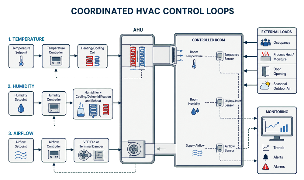
The parameters are coordinated through the HVAC system, but they are not interchangeable and do not necessarily change together:
- Temperature is controlled primarily through heating and cooling.
- Relative humidity is controlled through humidification, cooling and moisture removal, dehumidification, and reheat.
- Airflow is controlled through fan speed, dampers, terminal devices, duct-pressure control, or airflow-control devices.
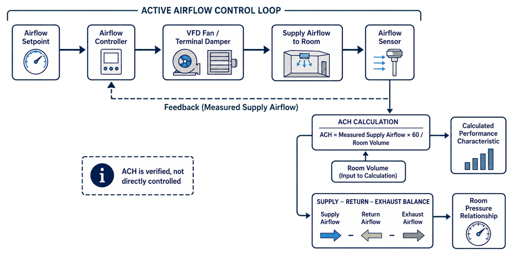
- Air changes per hour (ACH) are calculated from measured airflow and room volume. ACH is normally a verified performance characteristic rather than a directly controlled room variable.
A change in one parameter may affect another, but the extent and direction of that interaction depend on the HVAC system architecture, outdoor-air fraction, control sequence, internal loads, and operating mode.
Regulatory and Engineering Basis
21 CFR 211.46 requires adequate ventilation and, where appropriate, equipment for controlling air pressure, microorganisms, dust, humidity, and temperature. It also addresses filtration, recirculated air, exhaust systems, and contaminants generated during production.
For aseptic processing, FDA’s Sterile Drug Products Produced by Aseptic Processing—Current Good Manufacturing Practice provides additional expectations for HEPA-filtered air, airflow patterns, pressure relationships, environmental control, monitoring, and maintenance.
These requirements do not establish one universal temperature, relative-humidity, airflow, or ACH value for every GMP room. Approved values must be scientifically justified for the intended use and supported by design, qualification, and operational evidence.
Control Terminology
Environmental-control documents should distinguish requirements, controller targets, warning thresholds, and qualification criteria.
| Term | Meaning |
|---|---|
| Specified limit | Approved boundary associated with product, process, room, safety, or regulatory requirements |
| Acceptable operating range | Range within which routine operation is permitted |
| Normal control range | Narrower range the system is expected to maintain during stable operation |
| Control setpoint | Target value used by the controller |
| Deadband or hysteresis | Defined variation that prevents unnecessary or rapid controller switching |
| Alert limit | Early-warning threshold indicating drift or developing loss of control |
| Alarm or action limit | Threshold requiring a defined response, assessment, or operational action |
| Qualification acceptance criterion | Predetermined requirement used to determine whether an executed test passes |
These values may be related, but they should not be identical by default. A control setpoint should normally lie inside the approved operating range. Alert and alarm thresholds should account for normal variability, sensor accuracy, response time, deadband, measurement uncertainty, and the consequence of an excursion.
Establishing the Scientific Design Basis
Environmental conditions should originate from product, material, process, equipment, personnel, and facility needs rather than customary room values.
The documented design basis may address:
- Product and intermediate stability
- Hygroscopic or moisture-sensitive materials
- Powder flow, adhesion, compression, coating, drying, or granulation behavior
- Packaging-component dimensional stability
- Condensation, microbial, or corrosion risks
- Electrostatic-charge control
- Equipment and lighting heat loads
- Analytical-instrument requirements
- Occupancy, gowning, and personnel comfort where these affect performance
- Cleaning and sanitization activities
- Cleanroom classification and recovery requirements
- Contamination-control and containment objectives
- Seasonal outdoor temperature and moisture conditions
Approved requirements should identify which conditions are critical, where they apply, how long excursions may persist, and what evidence will demonstrate acceptable performance.
Temperature Control
Temperature control compares a measured value with a setpoint and adjusts heating or cooling output. Depending on the design, the principal feedback signal may be room temperature, return-air temperature, supply-air temperature, or a coordinated sequence using more than one measurement.
The design should address:
- Equipment and lighting heat loads
- Occupancy
- Outdoor-air fraction
- Supply-air temperature
- Heating- and cooling-coil capacity
- Control-valve authority
- Sensor location and response
- Startup, shutdown, and setback modes
- Recovery following door openings or other disturbances
A room sensor must represent the controlled environment. A sensor installed directly under a diffuser, beside heat-producing equipment, on an exterior wall, or near a frequently opened door may cause the controller to respond to a localized disturbance rather than the general room condition.
The control sensor also does not prove that every relevant room location is acceptable. Temperature mapping or distributed measurements may be required where spatial variation could affect products, materials, equipment, or operations.
Relative-Humidity Control
Relative humidity is the amount of water vapor present relative to the maximum amount the air can hold at the same temperature. Because that capacity changes with temperature, relative humidity can change even when the actual moisture content remains unchanged.
Cooling air without removing moisture generally increases relative humidity. Heating the same air generally decreases it. Cooling air below its dew point removes moisture; reheat may then be used to achieve the required supply-air temperature without restoring the removed moisture.
Humidity control may use:
- Steam or another qualified humidification method
- Cooling-coil dehumidification with condensate removal
- Cooling followed by reheat
- Desiccant or dedicated dehumidification systems for low-humidity service
- Coordinated control using room RH, dew point, or supply-air moisture measurements
The control sequence should prevent humidification and dehumidification from operating against each other because of overlapping control bands, inaccurate sensors, unsuitable sensor placement, or poor sequencing.
Dew point or moisture content may provide more useful diagnostic information than room relative humidity alone when temperature is changing.
Airflow Control
Airflow supports:
- Delivery of conditioned and filtered air
- Dilution and removal of airborne contamination
- Replacement of exhausted air
- Room-pressure relationships
- Removal of process heat and moisture
- Recovery following disturbances
- Containment or directional-airflow strategies
Unlike ACH, airflow can be an actively controlled variable. A typical closed control loop consists of:
- An airflow or duct-pressure setpoint
- A controller that compares the measured value with the setpoint
- A controlled device such as a variable-frequency-drive fan, terminal damper, or airflow-control valve
- An airflow sensor or transmitter that returns the measured value to the controller
Constant-volume systems may maintain fixed airflow while temperature and humidity outputs vary. Variable-air-volume systems may intentionally change airflow in response to load, pressure, occupancy, or operating mode. The control strategy must therefore define permitted airflow ranges and interactions with return and exhaust systems.
Airflow control must not be evaluated from supply air alone. The balance among supply, return, transfer, and exhaust airflow affects room pressure, door behavior, containment, and the applicable airflow patterns and pressure cascades.
Air-Change Performance
Air changes per hour express the volumetric airflow rate relative to room volume:
Where:
- = measured room supply airflow, typically in cubic feet per minute
- = room volume in cubic feet
- 60 = conversion from minutes to hours
ACH may be a design input used to establish the required airflow and a calculated result used during testing, balancing, or qualification. The HVAC system normally controls fan speed, duct static pressure, terminal airflow, damper position, or room pressure—not ACH itself.
ACH Requirements and Industry Benchmarks
There is no single ACH value that applies to every GMP room or every cleanroom classification. However, regulatory guidance and industry practice provide useful starting benchmarks.
FDA’s aseptic-processing guidance states that airflow sufficient to achieve at least 20 ACH is typically acceptable for ISO 8 supporting rooms. It also indicates that significantly higher air-change rates are normally needed for cleaner areas. These recommendations apply to aseptic-processing facilities and should not automatically be extended to every GMP room. Common engineering design ranges are approximately:
| Room type or classification | Common design range |
|---|---|
| Unclassified GMP support space | Approximately 6–15 ACH |
| Controlled but unclassified production space | Approximately 10–20 ACH |
| ISO 8 cleanroom | Approximately 20–30 ACH |
| ISO 7 cleanroom | Approximately 30–60 ACH |
| ISO 5 room supplied by non-unidirectional airflow | Often 40–100 ACH or more |
| ISO 5 unidirectional airflow zone | Normally specified by airflow velocity and pattern rather than room ACH |
These values are design conventions, not automatic acceptance criteria. Actual requirements depend on:
- Cleanroom classification and particle-generation rate
- Occupancy and operational activity
- Product exposure and process risk
- Equipment arrangement and airflow obstructions
- Air-distribution effectiveness
- Supply, return, transfer, and exhaust locations
- HEPA-filter coverage
- Recovery-time requirements
- Heat and moisture loads
- Exhaust-replacement and containment requirements
- Pressure strategy and permitted operating states
For ISO 5 unidirectional airflow, ACH can become misleading because protection depends primarily on airflow velocity, uniformity, direction, first-air protection, and demonstrated airflow behavior.
A higher ACH does not automatically produce better contamination control. Excessive airflow may increase turbulence, noise, drafts, energy demand, control instability, or pressure-balancing difficulty without improving performance. The selected ACH should therefore:
- Consider applicable regulatory guidance and established industry benchmarks.
- Be justified by the room’s intended use and contamination-control strategy.
- Be confirmed through airflow measurements, classification, recovery testing, airflow visualization, and pressure-performance results.
Relationships Between the Parameters
Temperature, humidity, and airflow are coordinated, but one parameter may change while the others remain essentially constant.
| Change or condition | Possible temperature effect | Possible humidity effect | Possible airflow or ACH effect |
|---|---|---|---|
| Increased occupancy | Adds sensible heat | Adds moisture | None in fixed-flow systems; possible increase in demand-controlled systems |
| Increased outdoor-air fraction | Depends on outdoor temperature | Depends on outdoor moisture | Total airflow may remain unchanged |
| Increased fan speed | May increase heat removal | May affect moisture removal | Usually increases airflow if system resistance permits |
| Increased cooling-coil output | Lowers supply-air temperature | Removes moisture only when air is cooled below its dew point | Normally no direct airflow change |
| Increased humidifier output | May slightly affect supply-air temperature | Increases moisture content | Normally no direct airflow change |
| Increased filter loading | May reduce conditioning capacity indirectly | May reduce moisture-control capacity indirectly | May reduce airflow unless the fan compensates |
| Door opening | May create a localized temperature disturbance | May create a localized RH disturbance | Temporarily changes airflow balance and room pressure |
| Seasonal change | Changes heating or cooling load | Changes humidification or dehumidification load | Total airflow may remain constant |
The actual effects depend on the HVAC architecture and control sequence. Single-pass systems are generally more exposed to seasonal outdoor loads than predominantly recirculating systems. Variable-flow designs may show greater interaction between airflow and temperature than constant-volume designs.
Sensor Selection and Placement
Control and monitoring sensors may serve different purposes and do not have to occupy the same location.
Control sensors should support stable feedback and adequately represent the controlled condition. Monitoring sensors may provide independent GMP records, alarms, or coverage of critical locations identified through mapping or risk assessment.
Sensor placement should consider:
- Room layout and airflow patterns
- Supply, return, transfer, and exhaust locations
- Heat and moisture sources
- Product, material, and equipment locations
- Doorways and local exhaust systems
- Mapping and qualification data
- Calibration and maintenance access
- Comparison with independent reference instruments
Sensors should not be placed where readings are dominated by:
- Direct supply-air discharge
- Return-air short-circuiting
- Solar gain or exterior walls
- Local heat or steam sources
- Washdown or cleaning activities
- Temporary material staging
- Routine door movement
Such a location may be appropriate only when the localized condition is intentionally being controlled or monitored.
Sensor relocation requires an impact assessment. A location that produces a more stable reading is not necessarily more representative of the controlled environment.
Design Capacity and Seasonal Performance
HVAC capacity should cover the expected combinations of external and internal loads, including:
- Summer temperature and moisture loads
- Winter heating and humidification demand
- Maximum occupancy and equipment heat release
- Process moisture generation
- Minimum and maximum outdoor-air positions
- Loaded-filter conditions
- Simultaneous exhaust operation
- Occupied, unoccupied, startup, shutdown, and reduced-flow modes
- Utility-capacity limitations or degraded service
Testing only during mild weather may not demonstrate performance during seasonal extremes. Where direct seasonal qualification is impractical, design calculations, commissioning data, controlled challenges, operating trends, and subsequent seasonal verification may be combined under an approved rationale.
Seasonal assessment is particularly important for single-pass systems and systems with high outdoor-air fractions.
Qualification and Verification
Qualification should demonstrate that installed equipment, sensors, control sequences, alarms, and room performance meet approved requirements.
Installation Verification
Installation verification may address:
- Sensor type, range, location, and identification
- Calibration status
- Heating and cooling coils
- Humidification and dehumidification equipment
- Fans and variable-frequency drives
- Airflow-measurement devices
- Control valves and dampers
- Utilities and drainage
- Automation and monitoring-system interfaces
- Approved drawings and sequences of operation
Operational Qualification
HVAC operational qualification should challenge:
- Temperature, humidity, and airflow control functions
- Stable operation through approved ranges
- Setpoint changes and mode transitions
- Fan, damper, valve, coil, and humidity-control responses
- Sensor failure and loss-of-utility responses
- Interlocks and alarms
- Recovery following representative disturbances
- Data recording and trending
- Access and configuration controls
Performance Verification
Performance verification may include:
- Temperature and humidity mapping
- Representative operational-load challenges
- Seasonal performance assessment
- Measurement of supply, return, transfer, and exhaust airflow
- Calculation of room ACH
- Pressure-differential testing
- Recovery testing
- Cleanroom classification
- Comparison of installed sensors with calibrated reference instruments
The applicable airflow, filtration, and pressure verification results should be evaluated with temperature and humidity performance. Acceptance criteria must distinguish individual readings, spatial variation, temporal stability, calculated results, measurement uncertainty, and permitted transient conditions.
Alerts, Alarms, and Excursion Assessment
The alarm strategy should define:
- Parameter and sensor involved
- Alert or alarm threshold
- Time delay
- Deadband or hysteresis
- Alarm priority
- Notification path
- Required response
- Escalation requirements
- Documentation requirements
- Permitted transient conditions
- Conditions requiring manufacturing restrictions or suspension
- Recovery and room-release requirements
A brief door-opening disturbance should not automatically receive the same response as a sustained loss of control. Justified time delays can prevent nuisance alarms from known, acceptable transients, but they must not conceal meaningful excursions.
An excursion assessment should consider:
- Magnitude
- Duration
- Affected room and location
- Product or material exposure
- Process stage
- Simultaneous airflow or pressure changes
- Condensation or visible moisture
- Environmental-monitoring results
- Equipment status
- Sensor accuracy and calibration status
- Previous trends
- Recovery time
Return to the control setpoint alone does not establish that an excursion had no product, process, or environmental impact.
Ongoing Monitoring and Lifecycle Review
Routine facility automation and monitoring should provide evidence that the HVAC system remains in control.
Ongoing review may include:
- Temperature, humidity, airflow, and duct-pressure trends
- Alarm frequency, duration, and recurrence
- Fan speed, damper position, and valve output
- Humidification and dehumidification demand
- Filter pressure drop
- Seasonal performance and recovery time
- Calibration and sensor-comparison results
- Changes in room use, occupancy, equipment, or operating mode
- Maintenance, repairs, and manual overrides
- Environmental-monitoring results
A room may remain within its specified limits while control performance deteriorates. Increasing oscillation, longer recovery, rising fan speed, growing valve demand, or repeated alerts may reveal declining capacity before an approved boundary is exceeded.
Results should be considered during periodic review, change control, investigations, and determination of targeted or comprehensive HVAC requalification.
Summary
Temperature, relative humidity, and airflow require distinct scientific bases, control methods, sensors, and acceptance criteria. They operate within one coordinated HVAC strategy but do not necessarily change together.
ACH should be treated accurately: it is calculated from measured airflow and room volume and is used to describe or verify room air-change performance. It is not normally the variable directly controlled by the HVAC feedback loop.
Effective control requires:
- Scientifically justified requirements
- Clear distinction between limits, ranges, setpoints, alerts, alarms, and qualification criteria
- Representative sensor placement
- Adequate capacity across seasonal and operational loads
- Separate but coordinated control sequences
- Qualified alarms and excursion-response procedures
- Performance-based airflow selection
- Lifecycle monitoring and trend review
The objective is not to maintain customary numbers. It is to demonstrate that the HVAC system consistently provides the conditions required for the room’s intended GMP use.