

Airflow Patterns and Pressure Cascades
Purpose and Scope
Airflow patterns and pressure relationships control how airborne contamination moves within and between manufacturing spaces. The control objective may include:
- Protecting exposed product from less-clean surrounding areas
- Containing hazardous or sensitizing materials
- Preventing cross-contamination between products or processes
- Supporting room cleanliness classification
- Removing particles, heat, moisture, vapors, or process emissions
- Protecting personnel and the surrounding environment
- Maintaining separation during routine movement and material transfer
There is no universally correct airflow direction or pressure hierarchy.
Positive pressure is commonly used for product protection. Negative pressure is commonly used for containment. Some operations require both functions and therefore need a combined strategy involving room pressure, airlocks, local enclosures, dedicated exhaust, or isolator technology.
Pressure differentials do not independently control contamination. They establish a driving force for airflow across a boundary. The complete control strategy must address:
- Supply, return, transfer, and exhaust airflow
- Room leakage
- Door position and opening frequency
- Airlock design
- Local exhaust
- Process equipment
- Control response
- Measurement locations
- Alarms
- Operating modes
- Failure conditions
Regulatory and Engineering Basis
21 CFR 211.42 requires facilities to provide adequate space and defined areas or other control systems necessary to prevent contamination and mix-ups.
21 CFR 211.46 requires adequate ventilation and, where appropriate, equipment for controlling air pressure, microorganisms, dust, humidity, and temperature.
For aseptic operations, FDA’s Sterile Drug Products Produced by Aseptic Processing—Current Good Manufacturing Practice guidance addresses HEPA-filtered air, airflow direction, pressure relationships, environmental control, and airflow visualization.
These requirements establish contamination-control outcomes. They do not prescribe one pressure value or one directional model for every facility.
The selected arrangement must be justified according to:
- Product exposure
- Process risk
- Room function
- Cleanliness requirement
- Material hazard
- Containment objective
- Adjacent operations
- Process enclosure
- Failure consequences
- Facility configuration
The supporting supply, return, and exhaust arrangements are described in HVAC System Architecture and Components.
Airflow Within a Room
Room airflow describes how supply air enters, moves through, and leaves the space. Effective airflow should:
- Deliver conditioned and filtered air to required locations
- Protect critical product-exposure points
- Dilute and remove airborne contamination
- Avoid unacceptable stagnant zones
- Avoid short-circuiting directly from supply to return
- Control contamination generated by personnel or equipment
- Support required temperature and humidity conditions
- Prevent uncontrolled transfer to adjacent spaces
Airflow distribution depends on:
- Supply-terminal type and location
- Return or exhaust location
- Supply and return quantities
- Room geometry
- Ceiling height
- Equipment arrangement
- Heat sources
- Process exhaust
- Personnel position and movement
- Door location
- Temporary staging
- Obstructions
- Required operating state
A high air-change rate does not prove effective airflow. Air can bypass critical locations, recirculate in stagnant areas, or be disrupted by equipment and personnel.
Detailed filtration and distribution considerations are addressed in HEPA Filtration and Air Distribution.
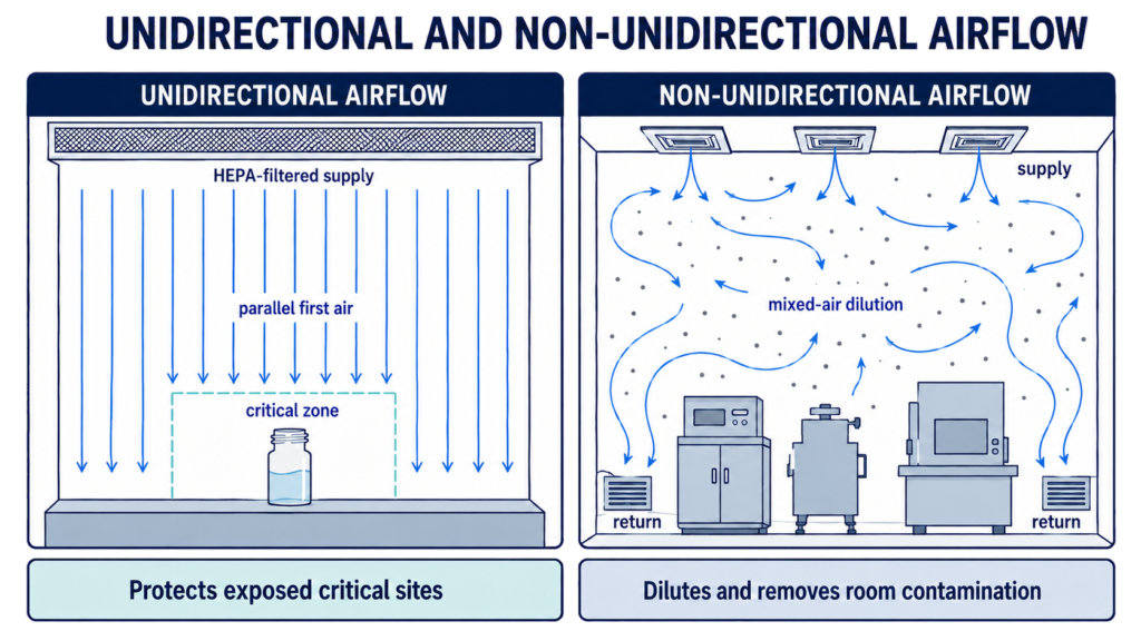
Unidirectional and Non-Unidirectional Airflow
Unidirectional Airflow
Unidirectional airflow moves filtered air in a substantially uniform direction and velocity across a protected zone. It is commonly used where exposed sterile product, components, or critical surfaces require first-air protection. The design should minimize:
- Turbulence
- Reverse flow
- Airflow shadowing
- Obstruction of first air
- Contaminant migration toward critical sites
- Disturbance from equipment or operator movement
Unidirectional airflow does not mean that every air particle moves in a perfectly parallel line. Performance is evaluated by whether the airflow consistently protects critical locations under representative operating conditions.
Non-Unidirectional Airflow
Non-unidirectional airflow uses mixed or turbulent distribution to dilute and remove airborne contamination. It may be appropriate for:
- Classified support rooms
- Nonsterile manufacturing areas
- Corridors and airlocks
- Closed-processing rooms
- Areas where localized unidirectional protection is provided separately
Its effectiveness depends on adequate distribution and contaminant removal rather than uniform displacement in one direction. The selected airflow pattern must reflect the process and exposure risk. Room classification alone does not define every required airflow characteristic.
Pressure Differential and Airflow Direction
Pressure differential is the difference in static pressure between two spaces.
When an opening or leakage path exists, air generally moves from the higher-pressure space toward the lower-pressure space. The actual direction and quantity depend on:
- Magnitude of the differential
- Size and location of leakage paths
- Door position
- Supply and exhaust balance
- Wind and building effects
- Elevator or stairwell effects
- Local exhaust operation
- HVAC control response
- Temperature differences
- Adjacent-room conditions
A displayed pressure differential is indirect evidence of directional control. It should be supported, where appropriate, by airflow measurements, balancing data, and airflow visualization.
A pressure relationship should always identify:
- Controlled room
- Reference space
- Required direction
- Normal target or operating band
- Acceptable tolerance
- Alert or alarm limit
- Time delay
- Permitted door condition
- Applicable operating mode
- Required response
A pressure value without a defined reference space is incomplete.
Positive-Pressure Product Protection
A positive-pressure room is maintained above the pressure of the adjacent reference space.
Its purpose is normally to cause air to move outward through leakage paths or open boundaries, reducing the potential for contamination to enter from the adjacent area.
Positive pressure may support:
- Aseptic processing
- Cleanroom protection
- Exposed-product operations
- Protection of cleaned equipment or components
- Separation from less-controlled corridors
- Protection of sensitive materials
Positive pressure does not eliminate the need for:
- Appropriate room classification
- HEPA filtration where required
- Controlled material and personnel flow
- Cleaning and disinfection
- Environmental monitoring
- Airflow visualization
- Door control
- Recovery verification
Excessive positive pressure can create:
- Difficult door operation
- Uncontrolled air leakage
- Transfer of dust or product to adjacent areas
- Instability when doors open
- Disturbance of adjoining pressure zones
- Increased HVAC demand
The pressure differential should be sufficient to support the required airflow direction but should not be increased without evaluating these consequences.
Negative-Pressure Containment
A negative-pressure room is maintained below the pressure of the adjacent reference space. Its purpose is normally to cause air to move inward, reducing the potential for hazardous or contaminating material to escape.
Negative pressure may support:
- Potent-compound handling
- Sensitizing materials
- Biological containment
- Dust-generating processes
- Hazardous-drug operations
- Solvent or vapor control
- Process isolation
- Quarantine or special-containment areas
Negative pressure alone does not demonstrate effective containment.
The complete strategy may also require:
- Source capture
- Closed processing
- Dedicated exhaust
- HEPA-filtered exhaust
- Safe-change filter housings
- Airlocks
- Sealed penetrations
- Appropriate cleaning methods
- Personnel protective measures
- Exhaust-failure response
- Containment verification
A room can remain negative while internal airflow permits contaminant escape from the process into the general room. Source containment and room containment must therefore be evaluated separately.
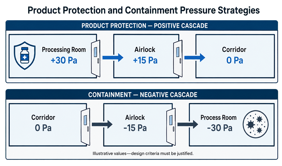
Pressure Cascades
A pressure cascade uses progressively different pressures across a sequence of connected spaces. For product protection, an illustrative sequence might be:
- Processing room: highest pressure
- Airlock: intermediate pressure
- Corridor: lowest pressure
For containment, the sequence may be reversed:
- Corridor: highest pressure
- Airlock: intermediate pressure
- Containment room: lowest pressure
The absolute pressure values are less important than:
- The intended direction across each boundary
- Stable operation within justified limits
- Compatibility with adjacent systems
- Door operation
- Alarm capability
- Recovery following disturbance
- Performance under expected operating modes
Pressure cascades should not be copied from another facility without considering room leakage, door configuration, control capability, and process risk.
Pressure Bubbles and Pressure Sinks
Not every pressure arrangement is a progressive cascade.
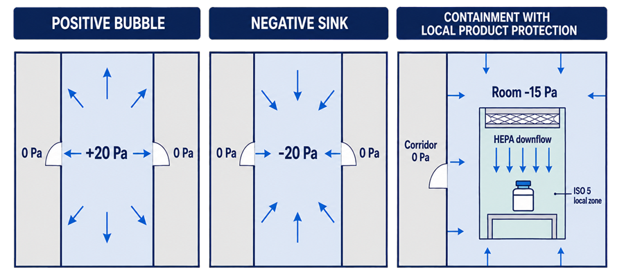
Positive-Pressure Bubble
A positive-pressure bubble is a room or suite maintained at a higher pressure than spaces on multiple sides. Air moves outward from the protected space toward adjacent areas. This arrangement may be appropriate where one room requires product protection but the surrounding rooms have similar lower-pressure conditions.
Negative-Pressure Sink
A pressure sink is a room or suite maintained below spaces on multiple sides. Air moves inward from adjacent areas toward the contained space. This arrangement may be appropriate for a hazardous-material room, wash area, decontamination space, or another defined containment zone.
Cascade Compared with Bubble or Sink
A cascade establishes a stepped sequence through several spaces. A bubble or sink establishes a local high or low point relative to surrounding spaces. The facility may use combinations of these concepts. For example:
- A positive cleanroom suite can form a bubble relative to the building.
- Individual rooms within the suite can have an internal pressure cascade.
- A hazardous process room can form a negative sink inside a controlled manufacturing area.
- An airlock can provide an intermediate pressure between conflicting zones.
The pressure diagram should show every controlled boundary rather than only the highest and lowest rooms.
Airlocks and Pressure Neutralization
Airlocks reduce direct communication between spaces having different cleanliness, pressure, or containment requirements. Types may include:
- Personnel airlocks
- Material airlocks
- Equipment airlocks
- Decontamination airlocks
- Pass-through chambers
- Waste-removal airlocks
An airlock may be operated as:
- An intermediate step in a pressure cascade
- A positive bubble
- A negative sink
- A neutral space with controlled sequencing
- A temporarily purged or decontaminated enclosure
No single airlock-pressure model is universally correct.
The selection depends on whether the dominant objective is:
- Protecting the cleaner room
- Containing the process room
- Separating incompatible areas
- Protecting both sides during transfer
- Supporting decontamination
- Controlling personnel or material movement
When both airlock doors are open, the intended separation may be substantially reduced or lost. Door interlocks, access procedures, alarms, purge time, or recovery requirements may therefore be needed.
Interlocks should not create an unsafe condition by preventing emergency egress.
Door-Opening Effects
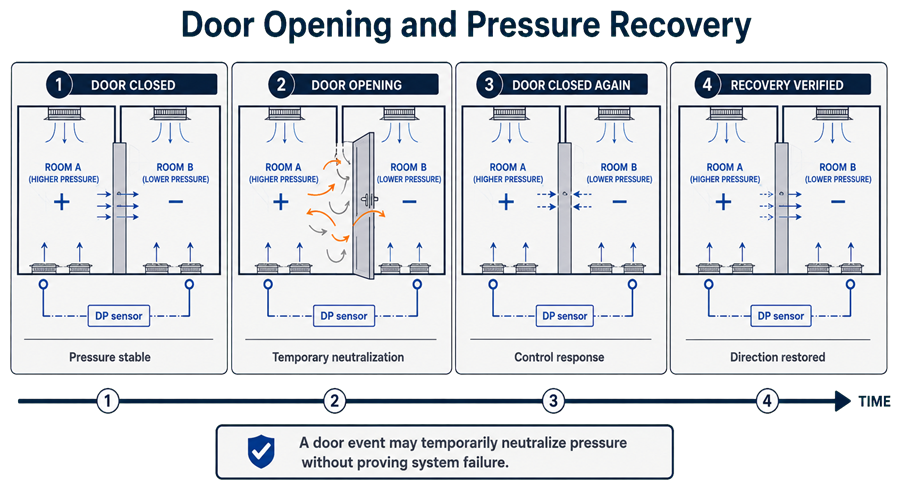
A closed-door pressure differential does not remain unchanged when the door opens. During opening:
- The effective leakage area increases sharply.
- Pressure may partially or completely neutralize.
- Directional airflow may weaken.
- Bidirectional exchange can occur.
- Door movement can generate turbulence.
- Personnel movement can carry contamination across the boundary.
- The control system may increase supply or exhaust airflow.
- Adjacent rooms may experience temporary pressure changes.
The magnitude and duration of the disturbance depend on:
- Door size and opening speed
- Door-open duration
- Frequency of opening
- Simultaneous door events
- Personnel and cart movement
- Airlock volume
- Pressure differential
- Supply and exhaust capacity
- Control-loop response
- Room leakage
- Adjacent pressure conditions
A brief pressure loss during an approved door-opening event is not automatically an HVAC failure. It must be evaluated against the approved operating strategy, alarm delay, door status, recovery time, and process condition.
A persistent failure to restore pressure after the door closes represents a different condition and requires investigation.
Door Interlocks and Operating Discipline
Where simultaneous door opening could compromise contamination control, controls may include:
- Mechanical interlocks
- Electrical interlocks
- Door-position switches
- Local indicators
- Audible or visual alarms
- Time-delay controls
- Access-control integration
- Procedural restrictions
- Defined maximum door-open time
- Recovery confirmation before opening the opposite door
Interlocks should be selected according to risk. They should not be installed merely because a room is called an airlock.
Operational controls should address:
- Propping doors open
- Moving oversized materials
- Cart staging
- High-traffic periods
- Emergency access
- Cleaning activities
- Maintenance activities
- Failed door closers
- Damaged seals
- Simultaneous nearby door openings
A technically sound pressure design can be defeated by uncontrolled door use.
Product-Protection and Containment Conflicts
Some processes require protection of the product from the room while also requiring containment of the process from personnel and adjacent areas. Examples may include:
- Aseptic processing of hazardous products
- Potent sterile compounds
- Biological materials requiring containment
- Cytotoxic manufacturing
- Operations generating hazardous aerosols
Simply selecting positive or negative room pressure does not resolve both objectives.
Possible strategies include:
- Negative-pressure room with a positive local protection zone
- Isolator maintained at the pressure appropriate to the product and hazard
- Closed processing inside a containment room
- RABS or local unidirectional-airflow protection
- Dedicated exhaust with controlled makeup air
- Cascaded airlocks
- Separate personnel and material transfer paths
- Double-door transfer systems
- Local source capture outside the critical product zone
- Pressure-controlled enclosures within a pressure-controlled room
The design must establish which boundary protects:
- Product
- Operator
- Adjacent rooms
- Building environment
- Exhaust discharge
- Transferred materials
A compromise pressure that does not reliably achieve either product protection or containment is not an adequate control strategy.
Supply, Return, Exhaust, and Transfer-Air Balance
Room pressure results from the combined effect of:
- Supply airflow
- Return airflow
- Exhaust airflow
- Transfer airflow
- Leakage through doors and penetrations
A simplified room balance can be expressed as:
Supply air = return air + exhaust air + transfer or leakage airflow
A positive room normally receives more supply air than is mechanically returned or exhausted. The excess leaves through controlled transfer paths or leakage.
A negative room normally exhausts or returns more air than it receives as supply. Makeup air enters from adjacent spaces or defined transfer paths.
The design should identify where transfer air is expected to move.
Uncontrolled leakage through:
- Ceiling voids
- Service penetrations
- Wall cavities
- Pass-throughs
- Damaged door seals
- Utility openings
can undermine the intended cascade even when displayed room pressures appear acceptable.
Local exhaust must be included in the room balance. Starting a dust collector, biosafety cabinet, fume hood, or equipment exhaust can shift the room from positive to neutral or negative.
Control Strategies
Room pressure may be maintained through:
- Fixed supply-to-return offset
- Fixed supply-to-exhaust offset
- Modulating supply airflow
- Modulating return airflow
- Modulating exhaust airflow
- Pressure-independent terminal devices
- Coordinated room-pressure control loops
- Suite-level pressure control
- Building-pressure control
Offset Control
An offset strategy establishes a defined difference among supply, return, and exhaust quantities.
It can be stable when:
- Room leakage remains consistent.
- Doors are normally closed.
- Process exhaust is predictable.
- Adjacent pressures are stable.
- Filters and airflow devices remain within their operating range.
Direct Pressure Control
A direct pressure-control loop uses a differential-pressure transmitter to modulate an airflow device.
It can respond to changes in room leakage or adjacent conditions but may become unstable if:
- The loop is tuned too aggressively.
- Door openings produce excessive response.
- Multiple room loops compete.
- Sensor tubing is affected by turbulence.
- Supply and exhaust loops are poorly coordinated.
- The control device lacks sufficient range or authority.
The control strategy should avoid excessive hunting after routine door events.
Differential-Pressure Measurement Locations
Measurement location directly affects the usefulness of pressure data. A differential-pressure transmitter or gauge should measure between clearly defined spaces. The pressure sensing points should generally avoid:
- Direct supply-air jets
- Return or exhaust grilles
- Door sweeps
- Frequently disturbed doorway locations
- Exterior wind effects
- Equipment exhaust discharge
- Locations vulnerable to blockage or damage
- Unrepresentative ceiling or wall cavities
The reference side must be identified. Where several rooms use one common reference, the stability of that reference pressure must be understood. Installation considerations include:
- Properly routed and identified tubing
- Protection against kinks and blockage
- Appropriate terminal fittings
- Accessible calibration points
- Correct high- and low-side connections
- Suitable instrument range
- Adequate accuracy and resolution
- Zero verification
- Protection against cleaning damage
A transmitter with a range far wider than the required differential may not provide adequate accuracy or resolution at the operating point. Permanent transmitters should be compared with an independent calibrated reference instrument during qualification and calibration.
Setpoints, Tolerances, and Acceptance Criteria
There is no universal pressure differential appropriate for every GMP boundary. The approved criteria should be based on:
- Required airflow direction
- Boundary leakage
- Door operation
- Room size
- Classification difference
- Product exposure
- Containment hazard
- Instrument capability
- Control-system capability
- Expected variability
- Alarm response
- Recovery requirement
The control strategy may distinguish among:
- Control setpoint
- Normal operating band
- Alert limit
- Action or alarm limit
- Qualification acceptance criterion
- Temporary door-event allowance
- Maximum recovery time
These values should not be treated as interchangeable.
A setpoint is the control target. A tolerance defines acceptable variation. An alarm limit identifies a condition requiring response. Qualification criteria define what must be demonstrated during testing.
Alarm limits should allow detection of meaningful loss of control without generating predictable nuisance alarms during approved door operation.
Pressure Alarms
Pressure alarms should identify conditions that could compromise product protection, containment, or the qualified environment. The alarm strategy should define:
- Parameter and monitored boundary
- Alarm setpoint
- Time delay
- Latching or non-latching behavior
- Door-status interaction
- Operating-mode suppression
- Local indication
- Remote annunciation
- Notification recipients
- Required response
- Documentation requirement
- Escalation criteria
- Reset authorization
A time delay may prevent a routine door opening from generating an unnecessary alarm. The delay must not be so long that a significant loss of containment or product protection remains undetected. Different events may require different responses:
- Brief approved door opening
- Door left open
- Failure to recover
- Fan failure
- Exhaust failure
- Pressure reversal
- Transmitter failure
- Communication failure
- Room placed in maintenance mode
An alarm acknowledgment does not resolve the underlying condition. Alarm trends should be reviewed for:
- Recurrence
- Specific rooms or shifts
- Door-use patterns
- Seasonal instability
- Filter-loading effects
- Control-loop hunting
- Maintenance needs
- Increasing recovery time
Monitoring and alarm-system architecture are addressed in Facility Automation and Monitoring Architecture and Concepts.
Operating-State Behavior
Pressure relationships should be defined for every relevant system state.
These may include:
- At rest
- In operation
- Occupied
- Unoccupied
- Reduced airflow
- Cleaning
- Material transfer
- Startup
- Shutdown
- Maintenance
- Decontamination
- Emergency operation
- Utility loss
- Fire or smoke-control mode
A pressure cascade demonstrated with all doors closed and no process equipment operating may not represent manufacturing conditions. Operational evaluation should consider:
- Maximum occupancy
- Routine door activity
- Material movement
- Process exhaust
- Equipment heat loads
- Dust-collection operation
- Biosafety-cabinet operation
- Simultaneous room use
- Reduced-flow modes
- Exhaust filter loading
- Supply filter loading
Pressure control should be qualified in the conditions that are credible and important to the process.
Startup, Shutdown, and Failure Response
Startup and shutdown sequences can temporarily reverse airflow direction. The sequence should consider:
- Supply-fan start
- Return-fan start
- Exhaust-fan start
- Damper opening
- Terminal-device enablement
- Pressure-loop enablement
- Alarm activation
- Stabilization time
- Release for manufacturing
For containment areas, exhaust may need to start before supply. For positive product-protection areas, the appropriate sequence may differ. Failure scenarios may include:
- Supply-fan failure
- Return-fan failure
- Exhaust-fan failure
- Damper failure
- Variable-frequency-drive failure
- Loss of electrical power
- Loss of automation
- Differential-pressure transmitter failure
- Filter loading
- Door remaining open
- Loss of local exhaust
- Simultaneous failures
There is no universal safe response. The appropriate response depends on whether the primary risk is:
- Contamination entering the room
- Hazardous material leaving the room
- Loss of both protection functions
- Personnel safety
- Building pressure instability
Failure-response testing should verify the integrated sequence rather than only confirming that an alarm appears.
Qualification and Verification
Qualification should demonstrate the intended airflow and pressure-control strategy under defined conditions. Applicable testing may include:
- Review of approved pressure-cascade diagrams
- Verification of rooms and reference spaces
- Supply, return, exhaust, and transfer-air measurements
- Differential-pressure measurement across each controlled boundary
- Comparison of installed transmitters with calibrated reference instruments
- Airflow-direction verification
- Door-opening challenges
- Airlock interlock testing
- Alarm and delay verification
- Recovery-time measurement
- Operating-mode testing
- Process-exhaust challenges
- Failure-response testing
- Startup and shutdown testing
- Assessment under representative dynamic conditions
- Airflow visualization
Detailed field methods are addressed in Airflow, Filtration, and Pressure Verification.
Airflow behavior that cannot be adequately demonstrated through pressure readings alone should be evaluated through Airflow Visualization – Smoke Studies.
Controls, alarms, interlocks, operating ranges, and failure responses are addressed during HVAC Operational Qualification.
Qualification results should record:
- HVAC operating mode
- Room operating state
- Door condition
- Occupancy
- Process-equipment status
- Exhaust-system status
- Instrument identification
- Actual readings
- Required direction
- Deviations
- Recovery behavior
A single closed-door reading does not establish complete operational control.
Routine Monitoring and Response
The monitoring frequency should reflect:
- Significance of the pressure boundary
- Product exposure
- Containment hazard
- System variability
- Failure detectability
- Door activity
- Alarm capability
- Historical performance
- Consequence of loss of control
Continuous monitoring may be appropriate where pressure loss could develop between periodic observations and materially affect product, personnel, or containment. Periodic manual checks may be adequate for lower-risk boundaries when supported by stable system performance and effective operational controls. An excursion assessment should consider:
- Actual value
- Duration
- Direction or reversal
- Door status
- Alarm delay
- Room and process state
- Product or material exposure
- Containment consequence
- Adjacent-room effects
- Environmental-monitoring data
- Recovery time
- Recurrence
- Instrument reliability
- Root cause
A momentary pressure neutralization during an approved door event is not equivalent to an unexplained prolonged reversal during exposed-product processing.
Maintenance and Change Control
Airflow and pressure relationships can be affected by changes that appear local or minor. Examples include:
- Fan-speed adjustment
- Damper adjustment
- Filter replacement
- Terminal-device replacement
- Rebalancing
- Sensor relocation
- Alarm-setpoint change
- Door replacement
- Door-seal replacement
- Door-closer adjustment
- Wall or ceiling penetration
- Addition of local exhaust
- Equipment relocation
- Change in room use
- Change in occupancy
- Control-logic modification
- Change in operating schedule
- Connection of another room to a shared system
Change assessment should consider effects on:
- Controlled room
- Reference room
- Airlocks
- Adjacent rooms
- Complete cascade
- Supply and exhaust balance
- Door operation
- Alarm performance
- Recovery time
- Containment
- Product protection
- Existing qualification
Periodic review and risk-based requalification triggers are addressed in HVAC Requalification Triggers and Periodic Review.
Common Weaknesses
Common airflow and pressure-control weaknesses include:
- Presenting clean-to-less-clean airflow as universal
- Using positive pressure where containment should control
- Using negative pressure without providing local product protection
- Selecting compromise pressure that achieves neither objective
- Assigning pressure values without technical justification
- Failing to identify the reference space
- Treating displayed pressure as complete proof of airflow direction
- Ignoring room leakage and transfer paths
- Ignoring process or local exhaust
- Assuming airlocks must always have intermediate pressure
- Failing to evaluate simultaneous door openings
- Treating every brief door-related excursion as system failure
- Ignoring failure to recover after door closure
- Locating pressure sensors in disturbed or unrepresentative areas
- Using instruments with unsuitable range or accuracy
- Setting alarms equal to normal operating tolerances
- Using excessive alarm delays
- Suppressing alarms without approved operating-mode logic
- Qualifying only with doors closed and rooms unoccupied
- Ignoring startup, shutdown, and reduced-flow behavior
- Changing airflow balance without evaluating adjacent rooms
- Failing to reconcile product protection with containment
- Assuming initial balance remains valid indefinitely
Summary
Airflow patterns and pressure relationships must be selected according to the actual contamination-control objective. Positive pressure generally supports product protection. Negative pressure generally supports containment. Pressure cascades, positive bubbles, negative sinks, airlocks, local enclosures, and dedicated exhaust systems provide different means of establishing the required directional control.
A defensible strategy defines:
- What is being protected or contained
- Which boundary performs each function
- Required airflow direction
- Pressure reference
- Setpoint and tolerance
- Alarm and delay
- Door behavior
- Recovery requirement
- Measurement location
- Operating states
- Failure response
- Qualification method
- Routine monitoring
- Change-control requirements
The correct principle is not that air must always move from cleaner to less-clean areas. Air must move in the direction required to control the identified product, contamination, containment, personnel, and environmental risks.