

HVAC System Architecture and Components
Purpose and Scope
HVAC architecture defines how outdoor air, return air, conditioned supply air, and exhaust air move through a facility and how the system controls temperature, humidity, airborne contamination, pressure relationships, and containment.
A GMP HVAC system does not require one universal architecture. The appropriate arrangement depends on:
- Intended use of the rooms
- Product and process characteristics
- Open or closed processing
- Sterile or nonsterile operation
- Cleanroom classification
- Contamination and cross-contamination risk
- Containment requirements
- Heat and moisture loads
- Required operating ranges
- Occupancy and operating schedules
- Failure consequences
- Monitoring requirements
- Maintenance and cleaning needs
- Energy and utility constraints
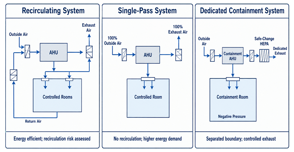
A centralized recirculating system may be appropriate for compatible areas. A single-pass system may be justified where recirculation presents an unacceptable risk. Dedicated systems may be required for containment or separation, while shared systems may be acceptable when their interfaces and failure effects are understood and controlled.
Architecture should therefore follow the approved requirements and risk assessment rather than a preference for one standard configuration.
Regulatory and Engineering Basis
21 CFR 211.46 requires adequate ventilation and, where appropriate, equipment for controlling air pressure, microorganisms, dust, humidity, and temperature. It also addresses filtration, recirculated air, exhaust systems, and control of contaminants generated during production.
For aseptic operations, FDA’s Sterile Drug Products Produced by Aseptic Processing—Current Good Manufacturing Practice guidance provides additional expectations for HEPA filtration, air cleanliness, airflow patterns, pressure relationships, environmental control, monitoring, and maintenance.
These sources establish required outcomes but do not prescribe one mandatory HVAC layout. The organization must select and justify an architecture capable of maintaining the conditions required for the intended manufacturing operation.
The GMP significance and criticality of different HVAC systems are explained in Role of HVAC in GMP Compliance.
Defining HVAC System Boundaries
Clear system boundaries are necessary for design review, qualification, maintenance, monitoring, change control, and investigation.
A system boundary may include:
- Outdoor-air intake
- Weather louver and intake screen
- Outdoor-air damper
- Return-air connection
- Mixing section
- Air-handling unit
- Heating and cooling utilities
- Humidification or dehumidification equipment
- Supply and return fans
- Supply, return, and exhaust ductwork
- Central and terminal filters
- Airflow-control devices
- Fire and smoke dampers
- Room supply terminals and returns
- Exhaust collection points
- Exhaust-treatment equipment
- Sensors and transmitters
- Local controllers
- Variable-frequency drives
- Building automation interfaces
- Environmental-monitoring interfaces
- Electrical and emergency-power interfaces
- Rooms and zones served
The boundary should identify where responsibility changes between systems. For example, the AHU may provide conditioned supply air, while a separate exhaust system maintains containment and another system records critical room conditions.
Drawings and system descriptions should make these interfaces explicit.
Principal HVAC Architecture Options
Recirculating Systems
A recirculating system returns part of the air from the served rooms to the AHU, where it is mixed with outdoor air, filtered, conditioned, and supplied again.
Advantages may include:
- Reduced heating and cooling demand
- Improved energy efficiency
- More stable temperature and humidity control
- Reduced outdoor-air treatment load
- Practical support for large controlled areas
Recirculation may be acceptable when:
- Returned air does not create an unacceptable cross-contamination risk.
- Products and processes served by the system are compatible.
- Contaminants are adequately controlled at their source.
- Filtration and dilution are appropriate.
- Return-air paths are understood.
- Failure or leakage effects are evaluated.
- Cleaning, monitoring, and change controls are adequate.
Recirculation should not be accepted solely because it is energy efficient. The assessment must address dust, aerosols, vapors, microorganisms, potent compounds, sensitizing materials, cleaning agents, and other contaminants that could enter the return-air system.
Single-Pass Systems
A single-pass or once-through system uses outdoor air as the supply-air source and exhausts the delivered air without returning it to the AHU.
Single-pass architecture may be appropriate where:
- Return-air recirculation creates an unacceptable contamination risk.
- Hazardous, sensitizing, biological, potent, dusty, or odorous materials are handled.
- Process exhaust cannot be safely returned.
- Containment requires a controlled directional airflow path.
- Regulatory, safety, or product requirements prohibit recirculation.
Single-pass systems generally require greater heating, cooling, humidification, or dehumidification capacity because all outdoor air must be conditioned.
Design should account for:
- Seasonal outdoor conditions
- Utility interruption
- Freeze protection
- Humidity extremes
- Exhaust-system reliability
- Building pressure balance
- Air-intake and exhaust-discharge separation
- Startup and shutdown sequencing
- Energy recovery, where safely applicable
Partial Recirculation
Many systems use a mixture of outdoor and return air.
The required outdoor-air fraction may be based on:
- Occupancy
- Contaminant dilution
- Room pressurization
- Exhaust-air replacement
- Process requirements
- Building-code requirements
- Humidity control
- Approved operating modes
Minimum and maximum outdoor-air positions should be defined where they affect environmental control. Damper position alone may not prove that the intended outdoor-air quantity is being delivered.
Dedicated Systems
A dedicated AHU serves a defined room, suite, process, product family, cleanliness zone, or containment boundary.
Dedicated systems can:
- Reduce cross-room and cross-product dependency
- Simplify containment
- Establish clearer system boundaries
- Allow separate operating schedules
- Reduce the impact of a system failure
- Support product-specific environmental conditions
- Simplify change-impact assessment
Dedication may be appropriate for:
- Aseptic-processing suites
- Highly potent or sensitizing products
- Biological containment areas
- Penicillin or other specially segregated operations
- Rooms requiring substantially different conditions
- Operations with incompatible contamination risks
- Areas requiring independent shutdown or decontamination
Dedication does not eliminate risk. Common utilities, automation, exhaust headers, shafts, mechanical spaces, power sources, or monitoring systems may still create shared dependencies.
Shared Systems
A shared AHU serves multiple rooms, suites, or operations.
A shared system may be acceptable when:
- Products and activities are compatible.
- Required room conditions can be maintained simultaneously.
- Return-air arrangements do not create unacceptable risk.
- Pressure relationships remain controllable under all expected operating modes.
- Different operating schedules do not destabilize the system.
- Shared-component failure effects are acceptable.
- Changes in one area cannot adversely affect another without detection.
- Cleaning and maintenance can be performed without uncontrolled impact.
- System boundaries and responsibilities are documented.
Shared systems require assessment of interactions, not merely confirmation that each individual room receives air.
Potential interactions include:
- Transfer through common return air
- Pressure shifts caused by doors or exhaust equipment
- Changes in one room’s airflow affecting another room
- Competing temperature or humidity requirements
- Fan-speed changes affecting multiple branches
- Unoccupied-mode changes affecting active areas
- Filter loading altering system balance
- Local exhaust affecting the complete building balance
Air-Handling Unit Functions
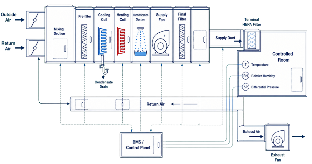
An air-handling unit conditions and moves air. Its exact component sequence depends on the required functions and climate conditions.
A typical AHU may include:
- Outdoor-air intake
- Return-air intake
- Isolation and control dampers
- Mixing section
- Prefilter
- Intermediate or fine filter
- Heating coil
- Cooling coil
- Dehumidification section
- Humidification section
- Supply fan
- Final AHU filter
- Discharge plenum
- Access sections
- Sensors and safety devices
Not every system requires every component, and the sequence may differ. The design review should establish why each component is included and how its location affects operation, cleaning, maintenance, and control.
Outdoor-Air Intake
The outdoor-air intake supplies ventilation air, replaces exhausted air, and supports building or room pressurization.
Its location should minimize intake of:
- Exhaust discharge
- Vehicle emissions
- Cooling-tower drift
- Generator exhaust
- Boiler exhaust
- Dust
- Standing water
- Roof contaminants
- Pest intrusion
- Process emissions
- Loading-dock contaminants
Important intake components may include:
- Weather louver
- Bird or insect screen
- Drainage provisions
- Intake damper
- Isolation damper
- Prefilter
- Freeze-protection devices
- Airflow-measurement station
- Temperature and humidity sensors
Intake location should be evaluated together with exhaust-discharge location and expected wind conditions. Physical separation alone may not prevent re-entrainment under unfavorable conditions.
Return-Air and Mixing Sections
Return air may be:
- Recirculated to the AHU
- Partially exhausted
- Fully exhausted
- Transferred between compatible areas
- Routed through treatment equipment
- Isolated during particular operating modes
The mixing section combines outdoor and return air in the required proportions.
Mixing should be sufficient to avoid:
- Local freezing at coils
- Stratified temperature conditions
- Unstable sensor readings
- Poor humidity control
- Uneven filter loading
- Inconsistent supply conditions
Dampers should have adequate range, authority, sealing capability, and access for inspection. Leakage through a nominally closed damper may be significant during shutdown, containment, decontamination, or emergency operation.
Filtration Stages
Filtration stages may protect the AHU, downstream ductwork, terminal filters, rooms, products, personnel, or the environment.
Common stages include:
Prefilters
Prefilters remove larger particles and protect coils, fans, and downstream filters.
Their performance affects:
- Coil cleanliness
- Pressure drop
- Energy use
- Downstream filter life
- Maintenance frequency
- Overall system cleanliness
Intermediate or Fine Filters
Intermediate filters reduce the particulate load reaching final or terminal filters.
They may improve:
- Downstream cleanliness
- HEPA-filter service life
- Duct cleanliness
- Room-particle control
- System recovery
Final AHU Filters
Final filters installed within or near the AHU provide additional filtration before air enters the supply ductwork.
They can protect downstream ducts but do not provide the same localized control as terminal filters. Leakage or contamination downstream of an AHU-mounted final filter can still affect the room.
Terminal HEPA Filters
Terminal HEPA filters are installed near the point where air enters the controlled room.
They can:
- Provide final filtration close to the protected space
- Reduce dependence on supply-duct cleanliness
- Allow filter-specific integrity testing
- Support localized airflow distribution
- Reduce the effect of upstream duct leakage
Terminal HEPA filtration is not automatically required for every GMP room. Its use should be based on cleanliness requirements, product exposure, contamination risk, and the required environmental-control strategy.
Filter selection, placement, integrity, housings, seals, access, and distribution are addressed in HEPA Filtration and Air Distribution.
Heating and Cooling Coils
Heating and cooling coils establish or modify supply-air temperature.
Heating sources may include:
- Hot water
- Steam
- Electric heat
- Refrigerant systems
- Heat-recovery systems
Cooling sources may include:
- Chilled water
- Direct-expansion refrigeration
- Glycol systems
- Central refrigeration
Coil design should consider:
- Required capacity
- Seasonal extremes
- Air velocity
- Pressure drop
- Control range
- Valve authority
- Freeze protection
- Condensate management
- Corrosion resistance
- Cleaning access
- Leakage detection
- Utility availability
Cooling coils used for dehumidification produce condensate. Drain pans and drain lines should be:
- Properly sloped
- Accessible for inspection and cleaning
- Constructed of suitable materials
- Designed to avoid standing water
- Properly trapped
- Protected against air bypass
- Routed to an appropriate drain
- Maintained to control microbial growth
An oversized coil or poorly selected control valve can produce unstable control even when adequate total capacity exists.
Humidification and Dehumidification
Humidity control may be required for:
- Product stability
- Material behavior
- Process performance
- Microbial-control considerations
- Electrostatic control
- Operator comfort in restrictive garments
- Condensation prevention
- Equipment operation
Humidification methods may include:
- Plant steam
- Clean steam
- Electric steam generation
- Atomized water
- Other engineered systems
The selected method should be evaluated for:
- Steam or water quality
- Potential contaminants
- Drainage
- Absorption distance
- Condensation
- Duct wetting
- Microbial growth
- Control response
- Maintenance
- Failure effects
Dehumidification may use:
- Cooling below the dew point followed by reheating
- Desiccant systems
- Dedicated dehumidification equipment
- Refrigerant-based systems
Humidification and dehumidification should not operate against each other because of poor control sequencing or sensor placement.
The basis for environmental limits is discussed in Temperature, Humidity, and Air Change Control Parameters.
Supply, Return, and Exhaust Fans
Fans provide the pressure and airflow needed to overcome resistance through filters, coils, dampers, ducts, terminals, and rooms.
Fan selection should consider:
- Required airflow range
- Static-pressure requirement
- Normal and maximum filter loading
- Duct and terminal resistance
- Control range
- Efficiency
- Noise and vibration
- Startup behavior
- Failure consequences
- Maintainability
- Redundancy requirements
Variable-frequency drives can adjust fan speed in response to airflow, duct-pressure, or room-pressure demand. The usable operating range should be established; a fan or drive may become unstable or inefficient when operated too far from its intended range.
Return and exhaust fans must be coordinated with supply fans. Independent changes can alter:
- Room pressure
- Building pressure
- Airflow direction
- Door operation
- Containment
- Exhaust capture
- Outdoor-air quantity
Fan status indication should distinguish between a command to run and evidence that the fan or airflow is actually present.
Dampers and Airflow-Control Devices
Dampers may provide:
- Airflow balancing
- Modulation
- Isolation
- Minimum outdoor air
- Pressure control
- Smoke control
- Fire protection
- Backflow prevention
- Emergency shutdown
- Decontamination isolation
Types may include:
- Manual balancing dampers
- Modulating control dampers
- Isolation dampers
- Fire dampers
- Smoke dampers
- Combination fire/smoke dampers
- Backdraft dampers
- Bubble-tight or low-leakage dampers
- Variable-air-volume terminal devices
- Constant-air-volume regulators
The required leakage rating and fail position should be based on the damper’s function.
A damper may be designed to fail:
- Open
- Closed
- In its last position
- To a mechanically defined safe position
The correct response depends on product protection, containment, freezing risk, smoke control, building pressure, and personnel safety.
Ductwork and Plenums
Ductwork distributes supply air and collects return or exhaust air.
Design considerations include:
- Construction material
- Leakage class
- Pressure class
- Internal surface condition
- Joints and seals
- Supports
- Access
- Cleanability
- Condensation control
- Insulation
- Identification
- Balancing provisions
- Fire and smoke protection
- Location of sensors and test ports
Duct systems should avoid unnecessary complexity, inaccessible components, and arrangements that trap water or contamination.
Internal duct insulation may present cleaning and particle-shedding concerns. Where used, its suitability should be evaluated for the application.
Access doors may be needed at:
- Coils
- Filters
- Dampers
- Humidifiers
- Drain pans
- Fans
- Turning vanes
- Sensors
- Fire and smoke devices
- Locations requiring inspection or cleaning
Duct leakage can affect energy use, airflow balance, room pressure, contamination control, and containment. Leakage significance depends on whether the duct is above or below surrounding pressure and where the leakage occurs.
Room Supply Terminals and Returns
Supply terminals introduce conditioned air into the room.
They may include:
- Ceiling diffusers
- Perforated face diffusers
- Swirl diffusers
- Grilles
- Terminal HEPA housings
- Unidirectional-airflow modules
- Fan-filter units
- Local air showers or curtains
Return or exhaust locations influence how contaminants are removed.
Their arrangement should consider:
- Room geometry
- Equipment location
- Personnel position
- Product-exposure points
- Heat sources
- Particle sources
- Door locations
- Process exhaust
- Cleaning access
- Obstructions
- Required airflow pattern
A high air-change rate does not correct poor distribution. Supply air can bypass occupied or critical areas, short-circuit directly to a return, or create stagnant zones.
Detailed airflow and pressure relationships are addressed in Airflow Patterns and Pressure Cascades.
Zoning and Pressure Boundaries
HVAC zoning divides the facility into areas with compatible requirements and risks.
Zoning may be based on:
- Cleanliness classification
- Product exposure
- Contamination risk
- Containment
- Product family
- Process type
- Temperature or humidity requirement
- Operating schedule
- Emergency response
- Decontamination strategy
- Maintenance boundary
A pressure zone may include several rooms controlled as a group or individual rooms with independent terminal control.
The design should distinguish among:
- Air-handling zone
- Temperature-control zone
- Humidity-control zone
- Pressure-control zone
- Cleanliness zone
- Containment zone
- Monitoring zone
- Fire or smoke zone
These boundaries do not always coincide. A room may share an AHU with adjacent rooms but have an independent temperature sensor, airflow-control device, room-pressure loop, and monitoring point.
Exhaust and Containment Arrangements
Exhaust systems remove air that should not be recirculated or transferred to other areas.
Applications may include:
- Dust-producing operations
- Solvent or vapor generation
- Hazardous or sensitizing materials
- Biological containment
- Potent compounds
- Local equipment extraction
- Fume hoods
- Biosafety cabinets
- Wash areas
- Sterilizer or dryer exhaust
- General toilet or service exhaust
A containment exhaust system may include:
- Dedicated ductwork
- Capture hood or equipment connection
- Isolation damper
- Prefilter
- HEPA filtration
- Safe-change or bag-in/bag-out housing
- Redundant exhaust fans
- Discharge stack
- Differential-pressure monitoring
- Filter-loading monitoring
- Decontamination connections
- Emergency-power support
Exhaust discharge should be located and designed to reduce re-entry into outdoor-air intakes, doors, windows, or occupied areas.
Local exhaust can affect room pressure and the complete HVAC balance. Equipment exhaust should therefore be evaluated as part of the room and system architecture rather than treated as an unrelated equipment utility.
Containment systems should define what happens during:
- Exhaust-fan failure
- Supply-fan failure
- Loss of power
- Filter loading
- Damper failure
- Door opening
- Fire alarm
- Emergency shutdown
- Loss of automation
- Maintenance or filter replacement
Redundancy and Standby Capacity
Redundancy should be based on the consequences of equipment failure, not applied uniformly.
Possible arrangements include:
- Duty and standby fans
- Multiple fans operating in parallel
- Redundant pumps
- Dual heating or cooling sources
- Redundant sensors
- Redundant controllers
- Emergency power
- Multiple AHUs serving a common header
- Spare filter capacity
- Alternate operating modes
Redundancy should be evaluated for common-cause failures. Two fans do not provide full redundancy when both depend on the same:
- Electrical source
- Controller
- variable-frequency drive
- Duct path
- chilled-water supply
- isolation damper
- sensor
- automation network
Standby equipment should be periodically operated or challenged where failure on demand would create unacceptable risk.
Automatic transfer should be tested under representative conditions. The assessment should consider the disturbance created during transfer and whether room conditions remain acceptable.
HVAC Control Loops
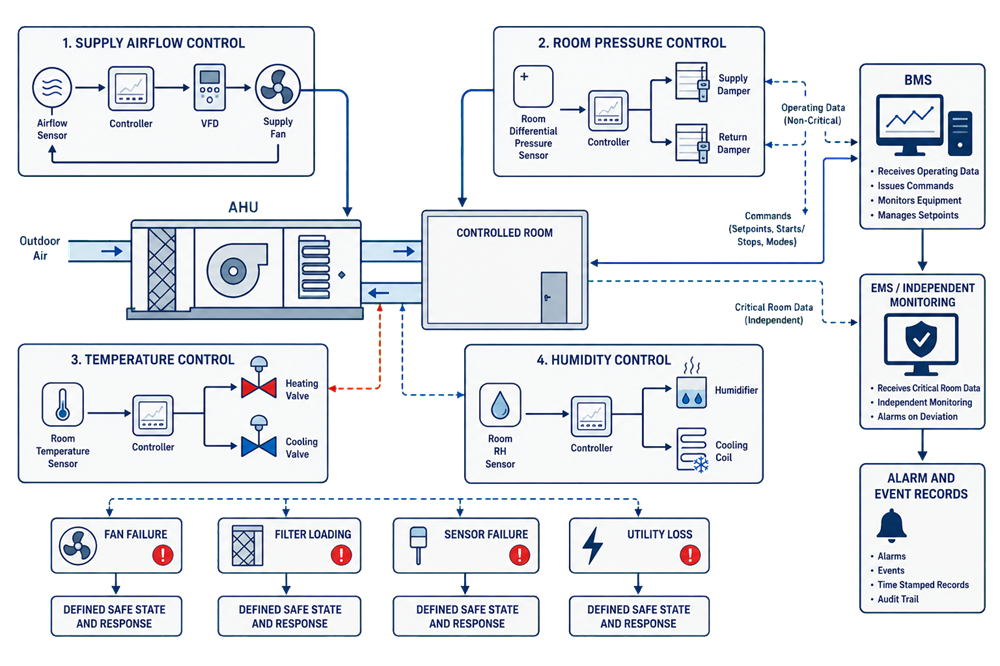
HVAC performance is maintained through coordinated control loops.
Supply-Airflow Control
Supply airflow may be controlled using:
- Fan-speed modulation
- Duct static pressure
- Airflow measurement
- Terminal-device demand
- Fixed-volume balancing
- Occupancy mode
A duct-static-pressure loop should maintain enough pressure for terminal devices to operate without creating unnecessary pressure or energy use.
Temperature Control
Temperature control may involve:
- Room or return-air sensor measures temperature.
- Controller compares the value with the setpoint.
- Heating or cooling valve is adjusted.
- Supply-air temperature changes.
- Room temperature responds.
Sensor location, valve size, control tuning, equipment capacity, airflow, and room load all affect loop performance.
Humidity Control
Humidity control may involve:
- Humidifier output
- Cooling-coil dehumidification
- Reheat
- Desiccant regeneration
- Outdoor-air adjustment
- Supply-air temperature control
Humidity loops often respond more slowly than temperature loops and can interact with them.
Room-Pressure Control
Room pressure may be controlled by:
- Fixed supply and return offsets
- Modulating supply airflow
- Modulating return airflow
- Modulating exhaust airflow
- Pressure-independent terminal devices
- Coordinated room and duct-pressure loops
Room-pressure control must accommodate door opening, equipment exhaust, filter loading, and adjacent-room pressure changes.
Filter-Loading Compensation
Increasing filter resistance can reduce airflow unless the fan or control system compensates.
The strategy should define:
- Normal differential-pressure range
- Alarm point
- Replacement criterion
- Maximum allowable resistance
- Effect on fan speed and airflow
- Required response when limits are reached
Sensors and Instrumentation
HVAC instrumentation may include:
- Temperature sensors
- Relative-humidity sensors
- Differential-pressure transmitters
- Airflow sensors
- Duct static-pressure sensors
- Filter differential-pressure gauges or transmitters
- Damper-position feedback
- Valve-position feedback
- Fan-speed feedback
- Fan current or status indication
- Smoke detectors
- Freeze-protection thermostats
- Condensate-level switches
- Utility-pressure or temperature sensors
Instrumentation should be selected and located according to its function.
A sensor used for control may not represent the same condition as a sensor used for independent GMP monitoring. For example:
- A return-air temperature sensor may provide stable system control.
- A room sensor may better represent the manufacturing environment.
- A local differential-pressure display may support operations.
- An independent transmitter may provide the official monitored record.
Critical instruments should have appropriate:
- Range
- Accuracy
- Resolution
- Response time
- Calibration
- Identification
- Access for service
- Protection from damage
- Alarm handling
- Failure detection
Sensor failure should not silently appear as a valid normal reading.
BMS, EMS, and Monitoring Interfaces
The building management system typically controls and supervises HVAC operation.
BMS functions may include:
- Starting and stopping equipment
- Modulating fans, dampers, and valves
- Maintaining setpoints
- Executing operating modes
- Generating alarms
- Displaying equipment status
- Recording trends
- Managing schedules
- Supporting maintenance
- Interlocking related equipment
An environmental monitoring system may independently collect critical GMP environmental data such as:
- Room temperature
- Relative humidity
- Differential pressure
- Nonviable particle results
- Other defined environmental parameters
Whether monitoring is performed through the BMS, EMS, a separate data system, or manual records depends on risk and system design.
The architecture should establish:
- Which system controls each function
- Which system produces the official GMP record
- Whether monitoring is independent of control
- How timestamps are synchronized
- How alarms are routed
- How data are retained
- How communication failures are detected
- What occurs during network or server failure
- Which data require audit trails
- How users and access are controlled
- How configuration changes are managed
Detailed automation architecture is addressed in Facility Automation and Monitoring Architecture and Concepts.
Operating Modes and Sequences
HVAC systems may have several defined modes:
- Occupied
- Unoccupied
- Production
- Cleaning
- Maintenance
- Shutdown
- Startup
- Standby
- Emergency
- Decontamination
- Reduced airflow
- Smoke-control mode
- Utility-loss mode
Each mode should define:
- Fans operating
- Damper positions
- Airflow quantities
- Pressure relationships
- Temperature and humidity control
- Exhaust operation
- Alarm behavior
- Monitoring status
- Permitted manufacturing activities
- Transition conditions
- Recovery requirements
Reduced-flow or unoccupied operation may save energy but must not compromise cleanliness, containment, pressure control, condensation prevention, or recovery before production begins.
Failure Modes and Safe States
Failure response should be designed intentionally.
Representative failure modes include:
- Supply-fan failure
- Return-fan failure
- Exhaust-fan failure
- Fan belt or coupling failure
- Variable-frequency-drive failure
- Loss of electrical power
- Loss of emergency power
- Heating-utility loss
- Cooling-utility loss
- Humidifier failure
- Filter loading
- Filter damage
- Damper failure
- Control-valve failure
- Sensor drift or failure
- Controller failure
- Network communication loss
- BMS server failure
- Frozen coil
- Condensate overflow
- Duct or housing leakage
- Fire or smoke signal
- Simultaneous equipment failures
The response may include:
- Alarm
- Controlled shutdown
- Standby-equipment start
- Damper repositioning
- Supply or exhaust isolation
- Process interruption
- Restricted room access
- Material protection
- Increased monitoring
- Product-impact assessment
- Recovery verification
- Requalification
There is no universal safe fan or damper position. A response that protects a positive-pressure aseptic area may be inappropriate for a negative-pressure containment room.
Failure-response testing should confirm the integrated sequence, not only the operation of individual alarms.
Maintainability and Cleanability
An HVAC system that cannot be safely inspected, cleaned, calibrated, or repaired will be difficult to keep in control.
Maintainability should be addressed during design.
Important provisions include:
- Adequate mechanical-space access
- Safe filter-removal space
- Access doors at serviceable components
- Coil-pull space
- Fan and motor-removal routes
- Lighting
- Working platforms
- Lifting provisions
- Isolation valves
- Electrical isolation
- Drain access
- Test ports
- Calibration access
- Damper access
- Sensor-removal access
- Component identification
- Safe-change filter housings
- Space for temporary testing equipment
- Protection of adjacent GMP areas during maintenance
The design should minimize the need to enter controlled rooms for routine HVAC maintenance.
Maintenance performed from the less-clean side of a terminal HEPA filter, where practical, can reduce disturbance to the controlled room.
Cleanability considerations include:
- Smooth and corrosion-resistant internal surfaces
- Properly drained pans
- Accessible coils
- Elimination of standing water
- Control of internal insulation
- Sealed penetrations
- Removable or cleanable components
- Appropriate cleaning methods
- Prevention of contamination release during service
Maintainability is part of control strategy, not merely a convenience for engineering personnel.
Supporting Utilities and Interfaces
HVAC performance depends on supporting systems that may include:
- Electrical power
- Emergency power
- Chilled water
- Hot water
- Steam
- Clean steam
- Glycol
- Refrigerant
- Compressed air
- Condensate drainage
- Building automation network
- Fire-alarm system
- Security or access-control system
- Process exhaust
- Environmental monitoring
- Equipment control systems
Interface requirements should define:
- Normal operating range
- Capacity
- Availability
- Failure indication
- Alarm response
- Isolation
- Recovery
- Maintenance responsibility
- Qualification responsibility
A qualified AHU cannot maintain conditions when the supporting utility lacks capacity or reliability.
Design Documentation
HVAC architecture should be represented through controlled documents appropriate to system complexity.
These may include:
- User requirements
- System classification
- Risk assessment
- Basis of design
- Design specifications
- Airflow diagrams
- System schematics
- Zoning diagrams
- Pressure-cascade diagrams
- Duct layouts
- Room data sheets
- Equipment schedules
- Instrument lists
- Point lists
- Control narratives
- Sequence-of-operation documents
- Alarm lists
- Cause-and-effect matrices
- Utility-consumption schedules
- Filter schedules
- Balancing reports
- Commissioning records
- Maintenance requirements
- Approved as-built drawings
Documents should agree with the installed configuration. Conflicting drawings, point lists, control narratives, and room requirements create uncertainty during qualification, operation, and investigation.
Qualification Considerations
Architecture determines the qualification boundary and testing strategy.
Qualification may need to verify:
- Installed AHU components
- Materials and identification
- Filter types and locations
- Duct routing and zoning
- Areas served
- Damper and valve installation
- Sensor and transmitter installation
- Utility connections
- Airflow direction
- Fan operation
- Control loops
- Operating modes
- Alarm and interlock functions
- Standby-equipment transfer
- Failure response
- Shutdown and restart
- Exhaust and containment operation
- Data and monitoring interfaces
- Restoration after utility interruption
The HVAC Qualification Strategy establishes the relationship among commissioning, system qualification, room-performance testing, and routine monitoring.
Installed configuration and documentation are addressed during HVAC Installation Qualification. Control loops, alarms, operating ranges, interlocks, failures, and recovery are addressed during HVAC Operational Qualification.
Qualification should not be limited to verifying that each component operates. It should demonstrate that the integrated system produces the required room and environmental conditions.
Lifecycle Configuration Control
HVAC architecture can be altered by changes that appear minor when evaluated individually.
Examples include:
- Changing a fan speed
- Changing a damper position
- Replacing a filter with a different model
- Relocating a sensor
- Changing a temperature setpoint
- Modifying control logic
- Adding process exhaust
- Adding heat-producing equipment
- Changing occupancy
- Adding or removing a wall
- Changing a room’s use
- Rebalancing one branch
- Extending ductwork
- Replacing a fan or motor
- Changing operating schedules
- Modifying unoccupied mode
- Connecting another room to a shared system
Changes should be evaluated for effects on:
- Airflow balance
- Pressure cascades
- Room recovery
- Filtration
- Temperature and humidity
- Containment
- Adjacent rooms
- Alarm limits
- Monitoring
- Supporting utilities
- Qualification status
- Existing drawings and documentation
Periodic review should confirm that the current physical and automated configuration still corresponds to the approved baseline. Detailed triggers are addressed in HVAC Requalification Triggers and Periodic Review.
Common Design and Lifecycle Weaknesses
Common weaknesses include:
- Assuming every GMP facility requires the same architecture
- Treating centralized HVAC as inherently superior
- Treating dedicated systems as automatically risk-free
- Sharing return air without evaluating cross-contamination
- Selecting single-pass air without evaluating utility capacity
- Failing to define system and room boundaries
- Failing to identify shared dependencies
- Locating outdoor-air intakes near exhaust discharge
- Ignoring interactions between local exhaust and room pressure
- Selecting fans without accounting for loaded filters
- Providing redundant equipment with common failure points
- Using damper command as proof of airflow
- Using fan command as proof of fan operation
- Placing sensors where they do not represent the controlled condition
- Using one sensor for control and GMP monitoring without assessing failure independence
- Failing to define operating modes
- Failing to define safe states
- Testing alarms without testing the resulting system response
- Allowing humidification condensation or wet ductwork
- Providing inaccessible filters, coils, dampers, or sensors
- Failing to provide adequate drain-pan slope and access
- Treating BMS and EMS functions as interchangeable without defining responsibilities
- Qualifying components without demonstrating integrated room performance
- Allowing as-built drawings to diverge from the installed system
- Modifying airflow or control logic without change assessment
A technically defensible design explains why the selected architecture is suitable, how it responds to failure, how it is monitored, and how it can be maintained throughout its operating life.
Summary
GMP HVAC architecture includes more than an AHU and supply ductwork. It integrates:
- Outdoor, return, supply, transfer, and exhaust air
- Air-handling and filtration stages
- Heating, cooling, humidification, and dehumidification
- Fans, dampers, ductwork, terminals, and room returns
- Zoning and pressure boundaries
- Recirculating, single-pass, dedicated, and shared arrangements
- Containment and exhaust systems
- Control loops
- Sensors and instrumentation
- BMS and EMS interfaces
- Redundancy and standby operation
- Failure modes and safe states
- Supporting utilities
- Maintainability and cleanability
- Qualification and configuration control
No single arrangement is universally required. The selected architecture must be appropriate for the intended operation, contamination and containment risks, required environmental conditions, monitoring strategy, failure consequences, and lifecycle-maintenance needs.