

HEPA Filtration and Air Distribution
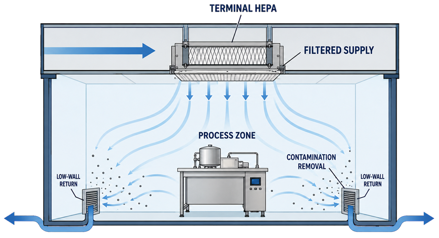
HEPA filtration and air distribution work together to control airborne contamination in cleanrooms, clean zones, and other GMP-controlled environments. The filter reduces the concentration of particles in the supplied air. The distribution system determines where that filtered air travels, how it interacts with equipment and personnel, and how generated contamination is removed.
Neither function should be evaluated independently. A filter can meet its specified efficiency yet fail to protect the room because of damaged media, an installation leak, housing bypass, inadequate airflow, poor diffuser selection, unsuitable return placement, or obstruction of the intended airflow path.
The required arrangement depends on the room classification, product exposure, contamination risk, process configuration, occupancy, containment requirements, and overall HVAC system architecture.
Regulatory and Technical Basis
21 CFR 211.42(c)(10) requires air supplied to aseptic-processing areas to be filtered through high-efficiency particulate air filters under positive pressure, regardless of whether the airflow is laminar or nonlaminar.
21 CFR 211.46 requires adequate ventilation and, where appropriate, equipment for controlling air pressure, microorganisms, dust, humidity, and temperature. It also addresses filtration of air supplied to production areas and control of contaminants introduced by recirculated or exhaust air.
FDA’s Sterile Drug Products Produced by Aseptic Processing—Current Good Manufacturing Practice provides additional recommendations for HEPA-filtered air, airflow patterns, installed-filter integrity testing, filter repair or replacement, documentation, and periodic retesting in aseptic-processing facilities.
Applicable technical standards include:
- ISO 14644-1:2015 for cleanroom classification by airborne-particle concentration
- ISO 14644-2:2015 for monitoring that provides evidence of continued cleanroom performance
- ISO 14644-3:2019 for cleanroom test methods, including installed-filter-system leakage testing and airflow testing
- ISO 14644-4:2022 for cleanroom requirements, design, construction, start-up, and lifecycle considerations
- IEST-RP-CC034.5 for HEPA- and ULPA-filter leak-testing practices
The applicable standards, filter classification system, acceptance criteria, and test methods should be defined in approved requirements and protocols. Requirements from different standards should not be combined without confirming that their definitions, test aerosols, instruments, and acceptance bases are compatible.
What a HEPA Filter Does
A high-efficiency particulate air filter uses a dense fibrous medium to capture airborne particles as air passes through it. The filter does not act as a simple screen with openings corresponding to one particle size.
HEPA-filter performance should therefore not be described merely as removing particles “down to 0.3 microns.” That statement incorrectly implies that 0.3 µm is a fixed pore size or that smaller particles pass through the filter.
A HEPA filter is specified by an efficiency or maximum penetration established under a defined test method. Depending on the governing standard and filter classification, performance may be rated:
- At a specified nominal particle size, commonly 0.3 µm under certain U.S. specifications
- At the most penetrating particle size, commonly abbreviated MPPS
- By overall efficiency, local efficiency, or both
The MPPS is the particle-size range at which the filter exhibits its greatest penetration under the applicable test conditions. Its exact value is not universally fixed and can vary with the filter medium, face velocity, aerosol characteristics, and test method. Particles both larger and smaller than the MPPS can be captured with equal or greater efficiency.
For many U.S. applications, HEPA filters are commonly specified at a minimum efficiency of 99.97 percent for approximately 0.3 µm particles. Other classification systems use different efficiency classes and MPPS-based testing. The approved specification must identify the applicable standard, filter class, test basis, rated airflow, and acceptance requirement.
Filter Selection
Filter selection should be based on the intended contamination-control function rather than the HEPA designation alone.
The specification should address:
- Applicable filter standard and classification
- Rated or nominal efficiency
- Particle size or MPPS basis
- Rated airflow and permissible operating range
- Initial and final resistance or pressure drop
- Filter dimensions and media area
- Frame material
- Separator or separatorless construction
- Gasket, gel seal, or other sealing arrangement
- Fire, smoke, temperature, humidity, and chemical compatibility
- Resistance to cleaning agents or decontamination methods
- Orientation and installation requirements
- Factory test and certification requirements
- Identification and traceability
- Handling and storage requirements
- Expected operating environment
A higher efficiency class is not automatically the better selection. Increased filtration efficiency may produce greater pressure drop, energy use, noise, or fan-capacity requirements. The complete system must deliver the required airflow under both initial and loaded-filter conditions.
Prefilters and intermediate filters may be installed upstream to reduce loading on final or terminal HEPA filters. Their selection can materially affect HEPA-filter service life, energy demand, duct cleanliness, and maintenance frequency.
Centralized and Terminal HEPA Filtration
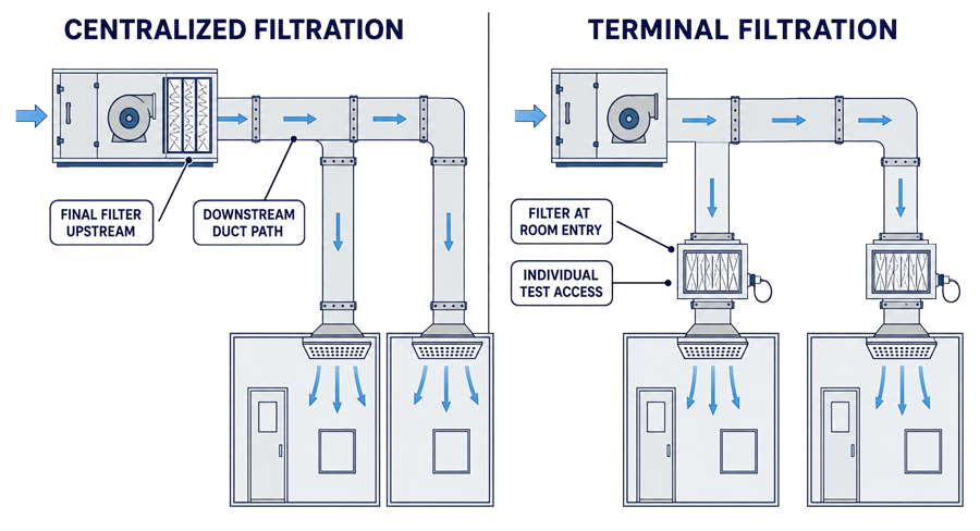
HEPA filters may be installed centrally within or near an air-handling unit, at room supply terminals, or in a combination of locations.
Centralized Filtration
A centralized final filter is installed upstream of the supply distribution system, commonly within an AHU or central filter bank.
Potential advantages include:
- Consolidated maintenance access
- Fewer individual terminal filters
- Protection of the main downstream air-distribution system
- Practical service for multiple compatible rooms
Limitations may include:
- Supply ductwork, joints, dampers, and terminals located downstream of the final filter
- Potential downstream contamination or leakage
- Greater difficulty relating a central filter to an individual room supply
- More complex installed-system leak testing
- Broader impact when one filter or housing fails
Terminal Filtration
A terminal HEPA filter is installed at or close to the point where air enters the controlled room or clean zone.
Potential advantages include:
- Final filtration close to the protected environment
- Reduced dependence on downstream duct cleanliness
- Filter-specific installed integrity testing
- Localized filter identification and maintenance
- Integration with perforated diffusers, unidirectional-flow modules, or fan-filter units
Terminal filtration does not eliminate the need for clean upstream ductwork, suitable housings, controlled maintenance, adequate airflow, or effective room distribution.
Neither arrangement is universally required for every GMP room. The selected configuration should be justified using room classification, process risk, duct arrangement, maintainability, failure consequences, containment, and qualification requirements.
Terminal Filter Housings and Installation
The installed filter system includes more than the filter medium. It may include:
- Filter media pack
- Filter frame
- Gasket or gel seal
- Knife edge or sealing surface
- Terminal housing
- Clamping or retention mechanism
- Diffuser face
- Upstream aerosol-injection port
- Upstream aerosol-sampling port
- Downstream scan access
- Differential-pressure connections
- Damper or airflow-balancing device
- Access door or room-side replaceable assembly
A filter can pass its factory efficiency test and still leak after installation. Possible causes include:
- Media damage during transport or handling
- Frame distortion
- Inadequate gasket compression
- Damaged or discontinuous gel seals
- Improper knife-edge engagement
- Contaminated sealing surfaces
- Loose or uneven clamping
- Cracked housing joints
- Leakage around fasteners or penetrations
- Incorrect filter orientation
- Damage during ceiling, duct, or diffuser work
Filters should be transported, stored, unpacked, lifted, and installed using approved procedures. They should not be handled by the media pack or protective screen. Storage conditions and stacking orientation should conform to the manufacturer’s instructions.
The installation should provide:
- Uniform sealing pressure
- Correct filter orientation
- Structural support without frame distortion
- Accessible test ports
- Sufficient downstream access for complete scan testing
- Protection from construction dust and moisture
- Identification visible from the service or room side
- Safe access for maintenance and replacement
- A method for controlling contamination during filter removal
Containment applications may require bag-in/bag-out or safe-change housings, decontamination connections, isolation dampers, and defined waste-handling controls.
Air Distribution Principles
Air distribution determines how filtered air enters, moves through, and leaves the controlled space.
The design should:
- Deliver filtered air to the locations requiring protection
- Avoid introducing contamination from less-clean areas
- Carry generated contamination away from exposed products and critical surfaces
- Limit stagnation and ineffective recirculation
- Avoid direct short-circuiting from supply to return
- Account for equipment, personnel, doors, partitions, and heat sources
- Support the required airflow patterns and pressure cascades
- Maintain acceptable performance in defined operating states
Air-change rate alone does not establish effective air distribution. A room can have a high calculated ACH while significant portions of the room remain poorly swept or while supply air bypasses the process area and travels directly to a return.
The distribution design should be confirmed using quantitative airflow measurements, room classification, recovery testing, pressure verification, and airflow visualization studies.
Unidirectional Airflow
Unidirectional airflow uses a substantially uniform air velocity and parallel airflow direction across a defined area.
It is commonly used to protect critical locations such as:
- Exposed sterile product
- Open sterile containers and closures
- Aseptic connections
- Filling points
- Critical equipment surfaces
- Sterile transfer paths
Effective unidirectional airflow depends on:
- Adequate HEPA-filter coverage
- Suitable airflow velocity and uniformity
- Stable direction
- Appropriate return or exhaust arrangement
- Limited obstruction of first air
- Equipment configuration
- Operator position and intervention technique
- Control of turbulence, reflux, and entrainment
First air is air supplied directly from the HEPA filter that reaches an exposed critical location without first passing over or around a potential contamination source.
A unidirectional-flow designation does not mean that every local air stream remains perfectly straight. Airflow bends around equipment and other obstructions. The relevant question is whether these disturbances compromise first-air protection or redirect contamination toward an exposed critical location.
Non-Unidirectional Airflow
Non-unidirectional airflow uses filtered supply air and mixing or dilution to reduce particle concentration and remove contamination from the room.
It is commonly used in supporting cleanrooms and controlled production areas where direct first-air protection is not required.
Performance depends on:
- Supply-diffuser type and coverage
- Supply-air volume
- Number and distribution of supply terminals
- Room geometry
- Equipment and personnel locations
- Contamination-generation rate
- Return and exhaust locations
- Recovery requirements
- Permitted occupancy and operating state
Non-unidirectional airflow may contain local mixing, recirculation, and turbulence. These conditions are not automatically failures. They become unacceptable when they produce stagnation, compromise required cleanliness, move contamination toward a protected operation, conflict with containment, or prevent adequate recovery.
Supply, Return, and Exhaust Placement
Supply terminals should distribute filtered air across the controlled portion of the room rather than create an isolated high-velocity stream.
Return or exhaust grilles should be positioned to support the intended contamination-removal path. Depending on the room and contaminant characteristics, returns may be located:
- Low on walls
- High on walls
- At ceiling level
- Behind or adjacent to process equipment
- Near identified particle, heat, vapor, or moisture sources
- At a containment capture location
Low-wall returns are often used with ceiling supply to encourage downward movement through the occupied zone. This arrangement is not universally optimal. High returns may be appropriate for heat removal, some non-unidirectional rooms, or particular process configurations.
Design evaluation should address:
- Short-circuiting between supply and return
- Areas shielded by tall equipment
- Stagnant locations behind or beneath equipment
- Turbulence over exposed product
- Door-opening effects
- Interaction with local exhaust
- Movement of contamination from personnel
- Thermal plumes from equipment
- Return paths blocked by staged materials
The required temperature, humidity, airflow control, and air-change performance should be considered together with the distribution arrangement.
Factory Filter Testing and Installed Integrity Testing
Factory filter testing and installed-system integrity testing serve different purposes.
| Test | Principal purpose |
|---|---|
| Factory efficiency or penetration test | Demonstrates that the manufactured filter meets its specified efficiency classification |
| Factory leak test | Identifies localized defects in the filter before shipment |
| Installed-system leak test | Identifies leakage through the filter media, frame, seal, housing, or installation after the filter is mounted |
| Room classification | Demonstrates airborne-particle concentration under a defined room state |
| Airflow testing | Demonstrates delivered air volume, velocity, uniformity, or direction |
| Airflow visualization | Shows how air travels through the room or protected zone |
Passing an installed HEPA integrity test does not establish room classification. Passing room classification does not prove that each installed HEPA filter and its sealing system are leak-free. Both types of evidence may be required.
Aerosol Challenge and Scan Testing
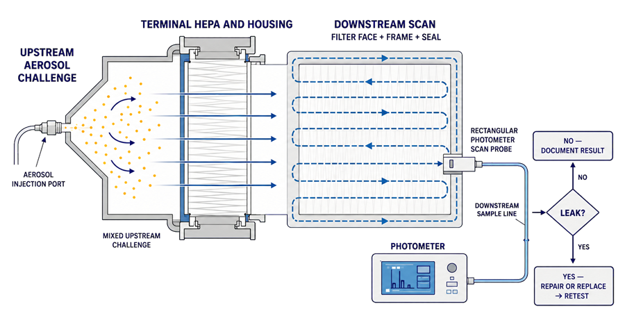
Installed HEPA-filter integrity testing normally introduces an approved aerosol upstream of the filter and measures downstream penetration using an aerosol photometer or another approved method.
The test should address:
- Suitable aerosol generation
- Adequate mixing of the upstream challenge
- Measurement and confirmation of upstream aerosol concentration
- Appropriate instrument setup and response
- Scanning of the complete downstream filter face
- Scanning of the filter perimeter, frame, seal, and housing interfaces
- Controlled scan-probe position and speed
- Identification and documentation of localized penetration
- Repair or replacement where required
- Confirmatory retesting after corrective action
An unsuitable upstream aerosol concentration can make the test unreliable. Insufficient concentration may prevent detection of a meaningful leak. Excessive concentration may saturate the instrument, contaminate the filter or room, or exceed the method’s operating range.
The aerosol should be sufficiently mixed so that the measured upstream concentration represents the challenge presented across the filter. Test-port location, injection location, duct configuration, airflow, and mixing distance should therefore be established during design rather than improvised during qualification.
Acceptance Criteria
Acceptance criteria should be defined before testing and should identify:
- Applicable standard, guidance, or approved method
- Test aerosol
- Instrument type and operating range
- Required upstream challenge concentration
- Required aerosol uniformity, where applicable
- Scan-probe dimensions
- Scan distance and speed
- Areas to be scanned
- Maximum permitted local penetration or leakage
- Requirements for total-leakage testing where used
- Repair limitations
- Retest requirements
- Documentation and investigation requirements
FDA’s aseptic-processing guidance states that, for the installed-filter scan method described in that guidance, a single-probe reading equivalent to 0.01 percent of the upstream challenge indicates a significant leak requiring filter replacement or, when appropriate, repair in a limited area followed by confirmatory retesting.
That value should not be inserted automatically into every HEPA-filter protocol. The applicable acceptance criterion must correspond to the facility’s regulatory scope, filter classification, test method, project requirements, and approved standard.
Filter Repairs
Localized repair may be acceptable when permitted by the applicable standard, manufacturer, facility procedure, and regulatory basis.
The repair program should define:
- Permitted repair materials
- Maximum individual repair size
- Maximum cumulative repaired area
- Restrictions near frames, separators, or seals
- Required curing conditions
- Repair identification and mapping
- Post-repair scan testing
- Approval requirements
- Conditions requiring replacement instead of repair
Repairs should not be used repeatedly to extend the life of a deteriorating or mechanically unstable filter. Replacement is generally appropriate when:
- Damage is extensive or distributed
- The permitted repair area would be exceeded
- The frame is distorted or damaged
- The filter media is wet, chemically affected, or contaminated
- The filter cannot be resealed reliably
- Repeated repairs fail integrity testing
- Pressure drop has become unacceptable
- The filter no longer supports required airflow
- Decontamination or process exposure has compromised suitability
- The manufacturer’s limitations have been exceeded
All repaired locations should be retested. A repair should not be accepted solely because room-particle classification remains satisfactory.
Filter Replacement Criteria
HEPA filters should not be replaced solely because they have reached an arbitrary calendar age. Replacement should be based on documented condition and performance criteria.
Potential replacement triggers include:
- Failed integrity testing
- Damage to media, frame, gasket, or gel seal
- Unacceptable or rapidly increasing pressure drop
- Inability to maintain required airflow or room pressure
- Excessive or repeated repairs
- Chemical, moisture, biological, or process contamination
- Filter exposure during a significant facility event
- Housing or sealing incompatibility
- Loss of traceability
- Manufacturer-recommended limitations
- Facility modification requiring another filter type or capacity
High differential pressure alone does not prove an integrity failure, and a low differential pressure does not prove filter integrity. Differential pressure is primarily an indication of resistance and loading. Integrity testing evaluates local penetration or bypass.
Replacement should be performed under an approved work plan that addresses room status, product protection, contamination control, filter handling, cleaning, installation verification, integrity testing, airflow rebalance, and return to service.
Qualification and Verification
Initial qualification should verify both the installed filter system and the resulting room performance.
Testing may include:
- Filter identification and certification review
- Installation and housing inspection
- Filter and housing integrity testing
- Airflow-volume measurement
- Face-velocity measurement where applicable
- Airflow-uniformity assessment
- Air-change calculation
- Room-pressure verification
- Airflow-direction testing
- Airflow visualization
- Recovery testing
- Cleanroom classification
- Alarm and monitoring verification
- Review under at-rest and operational conditions
The complete airflow, filtration, and pressure verification package should reconcile results rather than treating each test as an isolated pass-or-fail activity.
For example, a room may pass filter integrity testing but fail classification because the air volume is inadequate. It may pass classification at rest but show unacceptable airflow behavior during operation. It may meet airflow requirements but fail to maintain the intended room-pressure relationship.
Periodic Testing and Lifecycle Control
The testing frequency should be established according to:
- Regulatory and technical requirements
- Room classification and process criticality
- Aseptic or nonaseptic use
- Filter location and accessibility
- Previous integrity-test results
- Filter repair history
- Pressure-drop trends
- Environmental-monitoring performance
- Maintenance and shutdown history
- Facility changes
- Manufacturer recommendations
Lifecycle records should include:
- Filter manufacturer, model, class, and serial number
- Filter and housing location
- Factory certificates
- Installation date
- Initial integrity-test results
- Periodic test results
- Upstream challenge data
- Scan records and leak maps
- Repairs and repair locations
- Pressure-drop trends
- Airflow and balancing results
- Maintenance activities
- Deviations and investigations
- Change-control assessments
- Replacement date and reason
Additional testing or assessment may be required after:
- Filter replacement or reseating
- Housing or ceiling work
- Airflow rebalance
- Significant fan or control changes
- Room or equipment modifications
- Extended shutdown
- Decontamination activities
- Water intrusion
- Construction near the HVAC system
- Unexplained environmental-monitoring excursions
- Abnormal pressure-drop or airflow trends
- Suspected physical damage
The change should be assessed to determine whether targeted integrity testing is sufficient or whether airflow measurement, visualization, classification, recovery, pressure verification, or broader HVAC requalification is required.
Deviations and Investigations
A failed filter-integrity test should initiate controlled assessment rather than immediate unrecorded repair and repetition.
The investigation should consider:
- Exact leak location and magnitude
- Filter age and previous test history
- Frame, gasket, gel, knife edge, clamps, and housing condition
- Recent maintenance or ceiling activity
- Pressure-drop and airflow trends
- Environmental-monitoring and classification data
- Product and material exposure
- Room operating state
- Duration of possible loss of integrity
- Potential effect on adjacent rooms or processes
- Need for product-impact assessment
A passing retest confirms the condition after corrective action. It does not eliminate the need to assess the period during which the filter or installation may have been defective.
Summary
HEPA filtration is not accurately defined as particle removal “down to 0.3 microns.” A HEPA filter is rated according to an established efficiency or penetration test at a specified particle size or MPPS, depending on the applicable standard.
Reliable performance requires the combined control of:
- Appropriate filter specification
- Suitable filter location
- Correct handling and installation
- Sealed housings and terminal assemblies
- Effective supply and return distribution
- Appropriate unidirectional or non-unidirectional airflow
- Installed-system aerosol challenge and scan testing
- Controlled repairs and replacement
- Periodic testing and lifecycle review
A filter certificate alone does not establish cleanroom control. The installed filter, housing, air-distribution system, room configuration, and operational conditions must perform together to provide the required contamination-control outcome.