

HVAC Installation Qualification (IQ) Overview
HVAC installation qualification provides documented evidence that the installed HVAC system, its critical components, instruments, controls, utilities, and interfaces conform to approved requirements, design documents, specifications, and the accepted as-built configuration.
HVAC IQ establishes the physical and configuration baseline required before operational testing begins. It answers whether the correct system was installed correctly and whether objective evidence exists to support that conclusion.
IQ does not demonstrate that the system controls temperature or humidity, maintains room-pressure relationships, generates alarms correctly, delivers required airflow, passes HEPA-filter integrity testing, or supports cleanroom classification. Those are operational or room-performance determinations addressed through HVAC operational qualification and related verification activities.
The IQ scope should follow the approved HVAC qualification strategy, system boundary, intended use, and risk assessment. It should not become either a superficial equipment walkdown or an uncontrolled collection of vendor documents.
Purpose and Qualification Boundary
HVAC IQ should verify the installed items and records needed to establish a controlled baseline for the qualified system. Depending on the approved boundary, the scope may include:
- Outside-air intake, return-air, relief-air, and exhaust connections
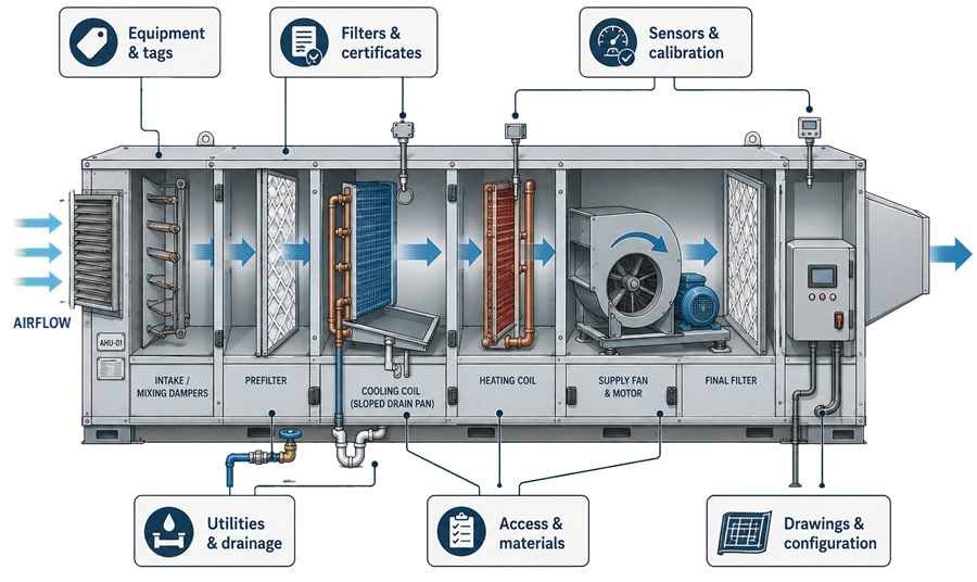
- Air-handling units and internal components
- Supply, return, transfer, and exhaust ductwork
- Central and terminal filtration
- Fans, motors, drives, coils, dampers, humidifiers, and dehumidification equipment
- Diffusers, grilles, terminal units, and air-volume-control devices
- Condensate systems, drains, traps, and isolation provisions
- Heating, cooling, steam, condensate, water, electrical, and compressed-air connections
- Sensors, transmitters, gauges, switches, actuators, and tubing
- Local panels, controllers, variable-frequency drives, and network interfaces
- Building-automation and environmental-monitoring interfaces
- Fire, smoke, access-control, process-equipment, and local-exhaust interfaces
- Equipment, instruments, duct branches, rooms, and utilities identified within the system boundary
The boundary should be consistent with the approved HVAC system architecture and as-built drawings. Where installation evidence is controlled under another package, the IQ should identify the interface, cite the accepted evidence, and explain what that evidence demonstrates.
IQ should not duplicate work solely because it was performed under a different controlled document. It also should not assume that another package covered an item merely because the item appears on a drawing.
Regulatory and Engineering Basis
21 CFR 211.46 requires adequate ventilation and, where appropriate, equipment for controlling air pressure, microorganisms, dust, humidity, and temperature. It also addresses filtration, recirculation, exhaust, and separation of penicillin air-handling systems.
21 CFR 211.63 requires equipment to be appropriately designed, adequately sized, and suitably located to facilitate intended operation, cleaning, and maintenance.
21 CFR 211.68 addresses automatic, mechanical, and electronic equipment, including routine calibration, inspection, or checking under a written program and appropriate controls over computer or related systems.
For aseptic facilities, FDA’s Sterile Drug Products Produced by Aseptic Processing—Current Good Manufacturing Practice provides additional recommendations concerning cleanroom design, HEPA filtration, air balance, pressure relationships, monitoring, maintenance, and facility suitability.
These sources define required outcomes and controls. They do not prescribe one universal HVAC IQ checklist. The protocol should translate approved requirements, design decisions, critical aspects, and risks into system-specific installation verifications.
IQ Prerequisites
IQ should begin when the installation is sufficiently complete, stable, and documented to permit meaningful verification.
Typical prerequisites include:
- Approved user requirements or other accepted requirement basis
- Approved system boundary and GMP-impact assessment
- Approved design specifications, equipment schedules, and control documents
- Current approved-for-construction or as-built drawings
- Completed installation work for the items being verified
- Controlled equipment and instrument lists
- Available manufacturer data and certificates
- Defined component criticality and sampling rationale
- Calibrated IQ test instruments
- Construction and commissioning status suitable for IQ execution
- Controlled management of open punch-list items
- Defined responsibility for discrepancies and document updates
Final as-built documents may not be fully approved at the first IQ walkdown. A controlled redline or verified turnover drawing may be used when the qualification plan permits it, provided discrepancies are recorded and the final approved as-built is reconciled before IQ closure or system release.
IQ should not be executed against obsolete drawings merely to preserve a schedule.
Equipment Identification and Configuration
The installed HVAC equipment should be reconciled with approved specifications, equipment schedules, purchase documents, and drawings.
Verification may include:
- Equipment tag and service description
- Manufacturer, model, serial number, and asset number
- Rated capacity and applicable operating limits
- AHU casing type, size, arrangement, and airflow orientation
- Component sequence within the AHU
- Fan type, motor rating, drive arrangement, and variable-frequency drive
- Coil type, rows, circuiting, materials, and connection size where critical
- Humidifier or dehumidification equipment type and capacity
- Filter stages, dimensions, ratings, and orientation
- Damper type, size, fail position, actuator, and accessibility
- Terminal-unit, diffuser, grille, and return configuration
- Exhaust equipment and treatment components
- Required redundancy and installed standby components
- Identification of rooms and zones served
Nameplate data should be recorded when it is relevant to a requirement or future traceability. Copying every nameplate value without explaining its qualification purpose creates volume rather than evidence.
Installed deviations from the specified manufacturer or model require documented assessment. Functional equivalence should not be assumed from similar appearance or nominal capacity.
AHU Internal Inspection
An internal AHU inspection should verify applicable installation details that cannot be established reliably from external observation or documentation alone.
The inspection may address:
- Correct section arrangement and airflow direction
- Internal cleanliness and absence of construction debris
- Condition of panels, seams, gaskets, insulation, and access doors
- Internal surfaces consistent with the specified materials and finish
- Absence of damaged insulation, exposed fibers, sharp edges, or corrosion
- Properly secured components and internal wiring or tubing
- Filter racks, retaining devices, seals, and bypass prevention
- Coil installation, support, accessibility, and connection orientation
- Fan and motor mounting, guards, flexible connections, and vibration isolation
- Damper blades, linkages, actuators, and seals
- Sensor and sampling-tube location
- Internal lighting and viewing provisions where specified
- Access for cleaning, inspection, maintenance, calibration, and filter replacement
- Drain-pan construction, slope, outlet location, and accessibility
- Traps and drain connections installed according to design requirements
The inspection should be performed safely under an approved access condition. IQ is not authorization to enter an operating AHU or bypass energy-control requirements.
Ductwork Installation and Cleanliness
Ductwork IQ should be risk-based and appropriate to the system type, location, construction method, and intended cleanliness or containment function.
Installation checks may include:
- Duct route and branch arrangement against drawings
- Duct dimensions or representative dimensions where critical
- Materials of construction and internal finish where specified
- Joint, seam, flange, gasket, and sealant type
- Correct installation of flexible connections
- Supports, hangers, bracing, and clearances
- Internal liner restrictions or condition
- Fire and smoke damper location and identification
- Control and balancing damper location and accessibility
- Access doors and inspection openings
- Test ports, aerosol-injection ports, and sampling locations
- Pressure-sensing taps and tubing connections
- Terminal-filter housing connections
- Insulation type, vapor barrier, and condition
- Identification of supply, return, exhaust, and transfer branches
- Protection from condensate, water intrusion, or unintended low points
Duct-cleanliness verification may include review of fabrication controls, shipping and storage protection, capped openings, installation housekeeping, cleaning records, and visual inspection of accessible representative locations.
The required verification should be defined before execution. “Ducts are clean” is not an adequate acceptance criterion unless the applicable cleanliness condition, method, locations, and disposition of identified debris are defined.
Where internal duct access is limited, the protocol should identify the evidence used, the sampling rationale, and any inaccessible areas. Visual inspection cannot demonstrate duct-leakage performance, airflow balance, or microbiological condition unless a separate approved method specifically addresses those questions.
Filters, Housings, and Certificates
IQ should establish the identity, suitability, orientation, condition, and traceability of installed filters and housings.
Verification may include:
- Filter stage and installed location
- Manufacturer, model, size, class, rating, and serial number where applicable
- Approved filter specification
- Correct airflow orientation
- Filter condition and evidence of damage or moisture exposure
- Gasket, gel seal, knife edge, clamp, rack, and housing configuration
- Prefilter and final-filter arrangement
- Terminal HEPA-filter housing identification
- Access for replacement and installed integrity testing
- Aerosol-injection and upstream-sampling provisions
- Differential-pressure taps and local indicators
- Factory filter certificates and shipment documentation
- Housing or factory test documentation where required
Factory certificates should be checked against the installed filter identity and approved specification. A certificate for the correct filter type but a different serial number does not establish traceability.
Certificate review is an installation and documentation activity. It does not replace installed-system HEPA filtration integrity testing. Aerosol challenge, scan testing, leakage acceptance, repair, and retesting belong to operational or room-verification activities rather than IQ.
Dampers and Air-Control Devices
IQ should verify that dampers and airflow-control devices are installed where intended and can be identified and accessed for subsequent testing and maintenance.
Checks may include:
- Outdoor-air, return-air, exhaust, relief, isolation, fire, smoke, and balancing dampers
- Airflow-control valves and terminal units
- Manufacturer, model, size, blade type, and leakage class where specified
- Airflow orientation and installed position
- Actuator type, power source, and fail position
- Linkage installation and mechanical stops
- Local identification and corresponding control-point tag
- Access for inspection, adjustment, and replacement
- Position feedback devices and associated wiring
- Sealing and physical condition
Damper stroking, position accuracy, fail response, interlocks, and sequence behavior are operational tests. IQ should verify the installed configuration and readiness for those tests, not claim functional acceptance.
Utilities, Coils, and Drainage
HVAC IQ should verify utility connections and installation features that affect safe, hygienic, and reliable operation.
Applicable checks may include:
- Heating-water, chilled-water, steam, condensate, refrigerant, compressed-air, and electrical connections
- Pipe size, material, service identification, and flow direction
- Isolation valves, control valves, strainers, vents, drains, and balancing devices
- Coil supply and return connections
- Valve and actuator identification
- Piping support and insulation
- Freeze-protection provisions
- Electrical disconnects and equipment grounding
- Condensate-drain size, slope, material, and routing
- Drain-pan slope toward the outlet
- Correct trap type, depth, orientation, and priming provisions
- Air gap or indirect connection where required
- Accessibility for cleaning and inspection
- Evidence that drainage does not create a backflow or standing-water condition
Water testing of a drain, valve stroke testing, coil-capacity testing, and freeze-protection challenges are not IQ solely because they concern installed utilities. They are commissioning or OQ activities whose records may be referenced after documented assessment.
Fans, Motors, and Rotation Evidence
IQ should verify the installed fan, motor, drive, guards, mounting, and identification against the approved design.
Checks may include:
- Fan type, size, arrangement, and airflow orientation
- Motor manufacturer, rating, voltage, enclosure, and efficiency class where specified
- Belt, coupling, sheave, or direct-drive arrangement
- Belt guards and other safety guards
- Base, support, vibration isolators, and flexible connections
- Lubrication provisions
- Variable-frequency-drive identity and rating
- Rotation-direction label or documented commissioning result
- Accessibility for inspection and maintenance
Fan rotation is normally established during startup or commissioning because the fan must be energized. IQ may accept a controlled rotation record after confirming that the tested fan and final electrical configuration match the installed system.
IQ should not energize equipment merely to convert an operational check into an installation check.
Instruments, Sensors, and Calibration Status
Critical HVAC instruments should be reconciled with the approved instrument index, drawings, control-point list, and calibration program.
Verification may include:
- Tag number and measured variable
- Manufacturer, model, and serial number
- Instrument type and principle of measurement
- Installed location and orientation
- Measurement range
- Calibrated range
- Accuracy or tolerance
- Engineering units
- Process connection, tubing, and impulse-line arrangement
- Sensor insertion depth where relevant
- Accessibility for calibration and replacement
- Local display or remote indication
- Calibration status, certificate, date, and due date
- Traceability to the calibration program
The measurement range, calibrated range, and operating range should not be treated as interchangeable. The installed instrument must be capable of measuring the required condition with suitable accuracy, and its calibrated range should cover the intended use and qualification challenges.
Sensor-location verification should determine whether the installed point matches the design basis. IQ does not demonstrate that the location is representative under operating conditions; that conclusion may require mapping, comparison, or other operational evidence.
An instrument found outside calibration or installed with the wrong range requires assessment of affected commissioning data, pending qualification tests, and any prior decisions based on that instrument.
Control Panels, Automation, and Configuration Baseline
HVAC IQ should establish the installed hardware and configuration baseline needed for subsequent control testing.
Verification may include:
- Panel tag, location, manufacturer, and enclosure rating
- Electrical supply, disconnect, and grounding
- Controller, input/output module, communication module, and power-supply identity
- Variable-frequency drives and local controllers
- Panel drawings, wiring diagrams, and input/output schedules
- Field wiring and device-tag reconciliation
- Network and communication connections
- Software, firmware, application, and configuration version identifiers
- Approved control narrative or sequence of operation
- Approved point list, alarm list, and setpoint list
- Backup or controlled copy of the released configuration
- Access-control and configuration-management arrangements
- Interface with the facility automation architecture
IQ should confirm that the intended configuration has been loaded or released and that the version is identifiable. It should not prove sequence logic, alarm generation, interlock response, trend accuracy, security roles, or backup restoration unless those tests are explicitly assigned to a separate automation qualification or OQ package.
Where configuration remains under active development, the affected IQ baseline should not be closed as final. Subsequent changes must be controlled and assessed for impact on completed verification.
Identification, Labeling, and Traceability
Equipment and component identification should be consistent across the physical installation and controlled records.
Applicable items include:
- AHUs, fans, coils, filters, dampers, and terminal units
- Instruments, control devices, and panel components
- Supply, return, exhaust, and transfer duct branches
- Utility piping and flow direction
- Electrical panels and disconnects
- Rooms, zones, and systems served
- Filter and test-port locations
- Drain connections
- Safety and maintenance-access points
Tag inconsistencies should not be dismissed as cosmetic when they could cause incorrect maintenance, calibration, testing, filter replacement, alarm response, or investigation.
Drawings and As-Built Verification
HVAC IQ should reconcile the installed system with the drawings required to operate, maintain, test, and change it safely.
Relevant documents may include:
- HVAC flow diagrams and schematics
- AHU arrangement drawings
- Duct layouts
- Room air-balance and pressure-cascade drawings
- Equipment schedules
- Instrument and control diagrams
- Control-panel and wiring drawings
- Utility drawings
- Filter schedules
- Room data sheets
- Control-point, alarm, and setpoint lists
- Sequences of operation
The walkdown should identify field differences, undocumented modifications, missing components, incorrect tags, inaccessible items, and drawing errors.
Minor drafting corrections may be managed through controlled redlines. A difference that affects system function, boundary, capacity, control strategy, maintenance access, qualification method, or risk control requires technical assessment and, where applicable, change control or deviation management.
The final drawing status should be unambiguous. “As-built available” is inadequate if the document does not represent the configuration qualified and released.
Materials of Construction and Installation Quality
Materials should be verified where they affect corrosion resistance, cleanability, contamination control, fire performance, durability, or compatibility with cleaning and decontamination agents.
Evidence may include:
- Approved specifications and data sheets
- Manufacturer certificates
- Purchase and receiving records
- Material markings
- Fabrication records
- Representative field verification
Verification may address AHU panels, internal liners, drain pans, coils, ductwork, gaskets, sealants, insulation, filter housings, and exposed room-side terminals.
Full material traceability is not automatically required for every HVAC component. The protocol should define which materials are critical, what evidence is sufficient, and whether representative sampling is justified.
Installation-quality observations should also address visible damage, corrosion, gaps, poorly sealed penetrations, unsupported components, exposed insulation, inaccessible service points, and other conditions capable of undermining operation or maintenance.
Access, Maintainability, and Testability
IQ should verify that critical components can be reached for the activities required throughout the lifecycle.
This may include access for:
- Filter inspection, replacement, and integrity testing
- Coil cleaning and inspection
- Drain-pan and trap inspection
- Fan, motor, belt, and bearing maintenance
- Damper inspection and adjustment
- Sensor calibration and replacement
- Test-port connection
- Aerosol injection and sampling
- Control-panel service
- Safe isolation of electrical and utility sources
- Cleaning and decontamination
An installed component is not suitably located merely because it fits within the mechanical space. Unsafe or impractical access can prevent the maintenance, calibration, and periodic testing required to preserve the qualified state.
Commissioning Records and Vendor Documentation
Commissioning records and vendor documentation may support HVAC IQ only after documented assessment confirms that the evidence is relevant, reliable, traceable, and applicable to the final installed configuration.
Potential records include:
- Factory and site acceptance records
- Equipment receiving and installation checklists
- Duct-fabrication and leakage-test records
- Pressure-test and flushing records
- Fan-rotation and startup records
- Filter certificates
- Coil, valve, damper, and sensor documentation
- Electrical inspection and loop-check records
- Panel-inspection and configuration records
- Manufacturer manuals and recommended maintenance information
- Testing, adjusting, and balancing records
The assessment should determine:
- What requirement or IQ check the record addresses
- Whether the tested item is uniquely identified
- Whether acceptance criteria were defined and met
- Whether the method and instruments were suitable
- Whether raw data and results are complete
- Whether deviations were documented and resolved
- Whether the record was reviewed by qualified personnel
- Whether later installation or configuration changes invalidated the result
- Whether supplemental verification is required
Vendor origin does not make a document acceptable or unacceptable. Suitability depends on the quality and applicability of the evidence.
Testing, adjusting, and balancing reports are normally prerequisites or supporting records for later operational verification. IQ may confirm their availability, identification, approved status, and correspondence with the installed system, but it should not accept room airflow performance solely through document presence.
Sampling and Verification Depth
Not every nut, bolt, duct joint, label, or noncritical component requires individual recording. Verification depth should be based on criticality, standardization, installation controls, detectability, and failure consequence.
A defensible sampling approach should define:
- Population being represented
- Common design and installation characteristics
- Critical attributes requiring complete verification
- Sample size and selection method
- Locations selected for accessibility or worst-case relevance
- Response to a failed sample
- Conditions requiring expanded verification
Critical filters, instruments, system boundaries, major equipment, control panels, and configuration identifiers commonly require complete verification. Repetitive noncritical items may be sampled when the rationale is documented.
Convenience sampling without a defined population or escalation rule is not risk-based verification.
Discrepancies, Punch-List Items, and Deviations
IQ discrepancies should be recorded when the installation or evidence differs from the approved acceptance basis.
The assessment should address:
- Exact item and location
- Requirement, specification, or drawing affected
- Nature and extent of the difference
- Potential effect on safety, product protection, containment, control, maintenance, or data reliability
- Effect on completed commissioning or qualification work
- Required correction, document update, or technical justification
- Need for expanded inspection
- Effect on OQ readiness
- Responsible owner and due date
- Final disposition and approval
An open item may remain at IQ closure only when its impact is understood, it cannot invalidate affected testing or intended use, interim controls are defined where needed, and completion is formally tracked.
Items affecting component identity, airflow path, filtration, drainage, instrument suitability, control configuration, safe access, system boundary, or critical documentation should not be treated as administrative punch-list items without technical assessment.
Correction followed by successful reinspection does not erase the original discrepancy. The record should preserve the finding, assessment, correction, and verification.
IQ Acceptance and OQ Readiness
The IQ conclusion should determine whether the installed HVAC system is adequately defined, documented, and ready for the next qualification phase.
Acceptance should confirm, as applicable:
- Approved scope and boundary were covered
- Critical equipment and components match the accepted design
- Ductwork, filters, dampers, utilities, drains, instruments, and controls are installed appropriately
- Required tags and identification are consistent
- Critical instruments have suitable ranges and current calibration
- Control hardware and configuration versions are identified
- Required access and test provisions are available
- Drawings represent the accepted as-built configuration
- Commissioning and vendor evidence was assessed before use
- Deviations are resolved or formally dispositioned
- Open items cannot invalidate planned operational testing
- Traceability to requirements and risks is complete
Readiness does not mean that operating performance has been demonstrated. It means that the installed baseline is sufficiently correct, stable, and controlled to permit meaningful operational testing.
If airflow balancing remains incomplete, control configuration is changing, critical instruments are unavailable, filters are not in final condition, or construction work can affect the verified installation, affected OQ or room testing should not begin.
What HVAC IQ Explicitly Excludes
Unless a controlled integrated protocol assigns and evaluates these activities separately, HVAC IQ does not establish:
- Fan, coil, humidifier, or dehumidifier operating capacity
- Control-loop performance
- Alarm thresholds, delays, notifications, or acknowledgments
- Interlock and failure-response operation
- Damper stroking or fail-position response
- Airflow volume or air-change performance
- Room differential pressure or airflow direction
- Temperature or humidity control
- HEPA-filter installed integrity
- Recovery performance
- Airflow visualization
- Cleanroom classification
- Performance at rest or in operation
- Seasonal performance
- Environmental-monitoring suitability
An organization may execute IQ and OQ activities within one combined protocol. The document format does not change the evidence type. Installation checks and operational tests should remain distinguishable, have appropriate prerequisites and acceptance criteria, and receive clear final disposition.
Lifecycle Use of the IQ Baseline
The accepted IQ package establishes the baseline for maintenance, calibration, change control, deviation assessment, periodic review, and requalification.
Subsequent changes should be assessed against this baseline, including:
- Equipment or component replacement
- Filter-type or housing changes
- Duct or terminal modifications
- Damper or airflow-control changes
- Sensor relocation or range change
- Control-panel, controller, or configuration changes
- Utility or drainage modifications
- Room-use or boundary changes
- Changes affecting access, cleaning, or testability
- Documentation corrections that reveal an installation difference
The response may require document revision, targeted installation verification, operational testing, room-performance verification, or broader requalification. Updating a drawing alone is insufficient when the physical or functional change affects previously accepted evidence.
Summary
HVAC installation qualification establishes the controlled as-built baseline required for reliable operational qualification and lifecycle control.
A complete HVAC IQ should:
- Define the system and interface boundaries
- Verify equipment, ductwork, filters, dampers, utilities, drainage, instruments, and controls
- Confirm critical materials, identification, access, and test provisions
- Reconcile the physical system with approved as-built documentation
- Verify instrument ranges and calibration status
- Establish the automation and control-panel configuration baseline
- Use commissioning and vendor records only after documented assessment
- Control discrepancies and unresolved items
- Conclude whether the installation is ready for OQ
- Explicitly exclude operational and room-performance claims
The objective is not completion of a generic checklist. It is documented evidence that the HVAC system intended for operational testing is the correct, traceable, maintainable, and controlled installation.