

Facility Automation and Monitoring Overview
Purpose and Scope
Facility automation and monitoring systems maintain, observe, alarm, record, and communicate conditions within GMP facilities.
These functions may be distributed among:
- Building Management Systems
- Environmental Monitoring Systems
- HVAC control systems
- Programmable logic controllers
- Direct digital controllers
- Equipment-local controllers
- Supervisory control and data acquisition systems
- Data historians
- Alarm-notification platforms
- Operator interfaces
- Reporting and quality-review applications
System names alone do not establish GMP significance. A system called a BMS may control HVAC equipment, record GMP-relevant environmental data, generate critical alarms, and retain the official record. An EMS may independently monitor critical conditions without controlling HVAC equipment. Another installation may combine several of these functions within one technical platform.
The appropriate lifecycle controls depend on:
- What the system does
- Which parameters it controls or monitors
- Whether it creates or retains GMP records
- How its data are used
- Whether it generates or communicates critical alarms
- Its relationship to product protection or containment
- The effect of incorrect operation, unavailable data, or delayed detection
- The reliability of its interfaces
- Applicable electronic-record and electronic-signature requirements
This article establishes the principal distinctions, boundaries, and integration concepts. Detailed architecture, qualification, and lifecycle-change requirements are addressed in the related articles within this subdomain.
Functions Before System Names
Facility automation should be assessed by function rather than by vendor terminology.
A system or subsystem may perform one or more of the following functions:
Control
A control function changes equipment operation to maintain a defined condition.
Examples include:
- Starting or stopping fans
- Modulating dampers
- Adjusting heating or cooling valves
- Controlling humidification or dehumidification
- Maintaining room pressure
- Modulating supply or exhaust airflow
- Changing equipment operating modes
- Initiating an interlock
- Moving equipment to a defined failure position
A control function acts on the process or facility.
Monitor
A monitoring function observes a parameter or status without necessarily changing equipment operation.
Examples include:
- Measuring room differential pressure
- Monitoring temperature or relative humidity
- Displaying fan or filter status
- Detecting a door-open condition
- Monitoring airborne particles
- Observing utility-system parameters
- Identifying communication or sensor failure
A system may monitor a parameter that another system controls.
Record
A recording function creates and retains data used as evidence of environmental or system performance.
Examples include:
- Time-stamped parameter values
- Alarm occurrence and acknowledgment
- Operator actions
- Setpoint changes
- Equipment-state changes
- Audit-trail entries
- Electronic review or approval
- Trend and report data
A displayed value is not necessarily a retained record. The system boundary must establish where the official record is created, stored, reviewed, and retained.
Alarm and Notify
An alarm function detects a defined abnormal condition. A notification function communicates that condition to designated personnel.
Examples include:
- Local audible or visual alarm
- Alarm displayed at an operator workstation
- Email, text, or telephone notification
- Escalation to another recipient
- Notification after an alarm remains unacknowledged
- Communication of system or interface failure
Alarm generation, alarm display, notification, acknowledgment, and response documentation may occur in different systems.
Review and Report
A review function supports evaluation of current or historical information.
Examples include:
- Real-time status review
- Daily alarm review
- Electronic record approval
- Trend evaluation
- Excursion assessment
- Periodic reporting
- Quality-unit review
A reporting tool may display data copied from another system without becoming the original data source. That relationship must be defined and verified.
Building Management System
A Building Management System generally supervises and controls facility mechanical and electrical systems.
Typical BMS functions include:
- Air-handling-unit control
- Supply, return, and exhaust-fan sequencing
- Heating- and cooling-coil control
- Humidification and dehumidification
- Damper and valve modulation
- Variable-frequency-drive control
- Room-pressure control
- Temperature and humidity control
- Operating-mode management
- Equipment-status indication
- Interlocks
- Energy management
- Operational alarming
- Engineering trending
- Operator interface
- Schedule control
A BMS may control GMP-critical conditions, but it may also control comfort-only offices, lighting, general utilities, or other non-GMP building services.
The complete BMS should therefore not automatically receive one uniform criticality classification. Criticality may differ among:
- Systems
- Control panels
- Controllers
- Applications
- Graphics
- Points
- Control loops
- Alarms
- Reports
- Interfaces
- Records
A BMS used only to control office comfort conditions ordinarily has a different GMP significance from a BMS controlling classified-room pressure, temperature, humidity, or containment exhaust.
Environmental Monitoring System
An Environmental Monitoring System generally provides independent or dedicated observation, alarming, recording, trending, and reporting of environmentally significant parameters.
Depending on its design, an EMS may monitor:
- Differential pressure
- Temperature
- Relative humidity
- Nonviable airborne particles
- Carbon dioxide
- Oxygen
- Refrigerated or controlled-storage temperatures
- Incubator conditions
- Utility parameters
- Equipment or room status
- Communication health
- Sensor condition
An EMS commonly provides:
- Continuous or periodic data acquisition
- Time-stamped electronic records
- Alert and action-level evaluation
- Alarm generation
- Notification and escalation
- Historical trending
- Report generation
- User-access control
- Audit trails
- Electronic review or approval
- Record retention and retrieval
An EMS normally monitors rather than directly controls HVAC equipment. This separation can provide an independent indication that the controlled environment remains within defined requirements.
However, independence should not be assumed merely because the system is called an EMS. Independence depends on the actual design, including:
- Sensor arrangement
- Power supply
- Input/output hardware
- Network path
- Server infrastructure
- Database
- time source
- Software platform
- alarm path
- common failure modes
Two applications receiving data from the same controller, network gateway, database, or transmitter may not provide meaningful independence from the shared component.
BMS and EMS Comparison
| Attribute | BMS or HVAC control system | EMS |
|---|---|---|
| Primary role | Operate and control facility equipment | Monitor, record, alarm, trend, and support review |
| Typical action | Changes equipment output to maintain conditions | Detects and documents environmental conditions |
| Common inputs | Sensors, equipment status, commands, schedules | Independent or shared sensors, monitoring instruments, transferred data |
| Common outputs | Fan, damper, valve, heater, humidifier, drive, interlock commands | Records, alarms, notifications, trends, reports |
| Typical users | Engineering, facilities, maintenance, operations | Operations, microbiology, engineering, validation, quality |
| Data purpose | Control, troubleshooting, maintenance, and possibly GMP evidence | Environmental oversight and commonly GMP evidence |
| Official GMP record | Possible, depending on intended use | Common, but must be explicitly defined |
| HVAC control authority | Common | Normally absent |
| Alarm focus | Equipment and operating-condition response | Environmental significance and quality escalation |
| Qualification focus | Control sequences, modes, interlocks, alarms, failure positions, recovery | Acquisition, accuracy, records, limits, alarms, notification, audit trails, review, retention |
| Part 11 applicability | Based on regulated electronic-record or signature use | Based on regulated electronic-record or signature use |
| Quality oversight | Proportional to GMP impact and data use | Common where records support GMP decisions |
This comparison describes typical practice, not mandatory architecture. One configured platform can perform both BMS and EMS functions. When functions are combined, the requirements and controls applicable to each function remain necessary.
Shared Sensors and Separate Functions
A BMS and EMS may use:
- Separate sensors
- A shared sensing element with separate outputs
- One transmitter with multiple independent outputs
- A signal splitter
- A gateway
- A BMS-to-EMS data interface
- A shared supervisory platform
- A common database or historian
Each arrangement creates different dependencies.
Separate Sensors
Separate sensors can provide stronger functional independence.
For example:
- A BMS sensor controls room pressure.
- An independent EMS sensor records and alarms room pressure.
This arrangement can detect certain control-sensor failures because the monitoring system does not depend on the same measurement chain.
Separate sensors may still share:
- Pressure tubing
- Pressure reference location
- Electrical power
- Network infrastructure
- Physical installation
- Calibration standards
- Environmental exposure
The independence claim should therefore identify the actual common dependencies.
Shared Sensing Element
One sensing element may provide signals to both the BMS and EMS.
This can reduce installation complexity and disagreement between instruments, but failure of the common element can affect both control and monitoring.
The design should address:
- Signal isolation
- Output scaling
- Failure detection
- Calibration effect
- Maintenance interruption
- Signal disagreement
- Ownership
- Which system displays the authoritative value
- Response when one output fails
Data Transferred Between Systems
The BMS may transfer values, status, or alarms to the EMS.
In this arrangement, the EMS record depends on:
- BMS sensor accuracy
- Controller processing
- Point configuration
- Network communication
- Gateway mapping
- Time synchronization
- Data-transfer frequency
- EMS ingestion
- Database storage
The EMS does not create independent evidence merely by copying BMS data. It creates a separately retained record of data generated through the upstream BMS measurement chain.
This architecture may be acceptable when its intended use, dependencies, controls, and failure responses are documented and qualified.
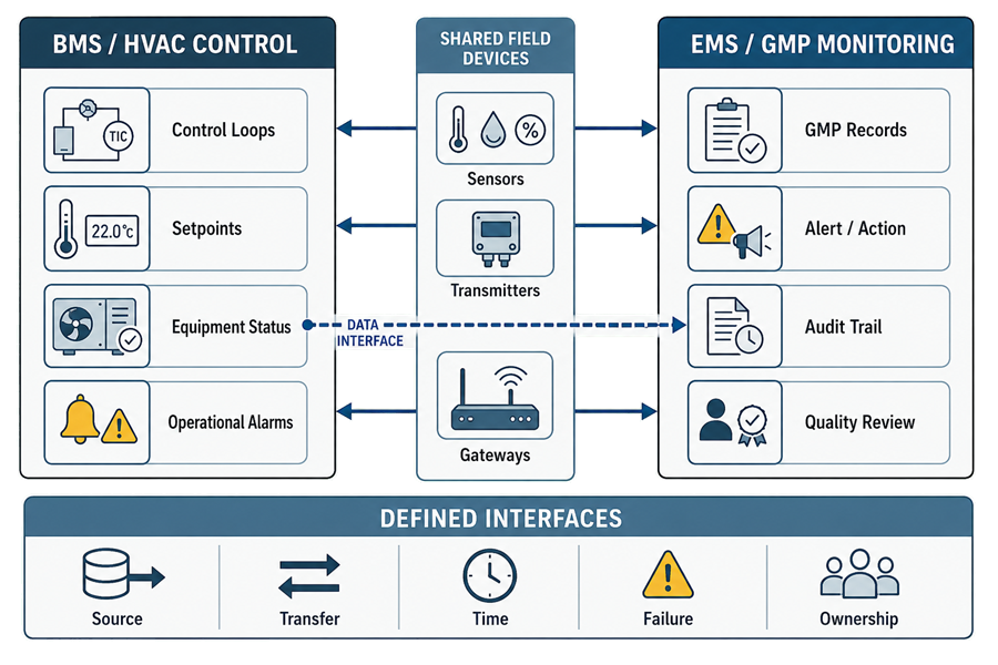
BMS and EMS boundaries should be defined by assigned functions rather than platform names. Shared field devices and transferred data can support both systems, but each measurement, alarm, record, interface, and failure response requires a defined source and owner.
Local Controllers and Distributed Control
Facility automation is commonly distributed across several layers.
A typical arrangement may include:
- A sensor measuring the condition
- A transmitter converting the measurement into a usable signal
- A local controller executing the control logic
- An actuator changing equipment output
- A supervisory BMS displaying status and accepting permitted commands
- An EMS recording critical conditions
- A historian or database retaining data
- An alarm platform notifying personnel
- A reporting application presenting information for review
Local control may continue when the supervisory server or network is unavailable. This can preserve HVAC operation during a communication failure.
The design should define:
- Which functions reside in the local controller
- Which functions require the supervisory platform
- What happens when communication is lost
- Whether local data are buffered
- Whether buffered data are transferred after recovery
- Whether alarms remain available
- Whether operators can control equipment locally
- How local changes are secured and documented
- How local and supervisory configurations remain consistent
- How recovery is verified
A graphical interface may suggest centralized control even when the actual control logic resides in multiple field controllers. Qualification and change control must address the installed architecture rather than only the supervisory screen.
System Boundary Determination
The system boundary identifies the components and services necessary for intended operation and reliable records.
The boundary may include:
- Sensors
- Transmitters
- Signal conditioners
- Input/output modules
- Controllers
- Actuators
- Control panels
- Operator workstations
- Servers
- Virtual machines
- Databases
- Historians
- Network switches
- Gateways
- Interface engines
- Notification services
- Time servers
- Domain or directory services
- Backup infrastructure
- Reporting tools
- Remote-access components
- Mobile notification devices
- Supporting procedures
- Responsible personnel
Boundary determination should identify both technical and procedural dependencies.
For each boundary component, document:
- Function
- Owner
- GMP significance
- Configuration authority
- Maintenance responsibility
- Calibration requirement
- Data generated or transferred
- Failure effect
- Backup or redundancy
- Qualification or verification approach
- Change-control requirements
A narrow boundary that excludes critical infrastructure can leave significant risks untested. An unnecessarily broad boundary can make routine infrastructure changes difficult to manage without improving control.
The boundary should be broad enough to include every dependency that can materially affect intended function or regulated data, but specific enough to assign proportionate controls.
Point and Function Inventory
A point inventory is necessary when one automation platform contains many functions with different GMP significance.
The inventory should define, as applicable:
- Point identifier
- Description
- Physical location
- Sensor or source device
- Engineering unit
- Input or output type
- Control or monitoring function
- Scaling
- Range
- Accuracy requirement
- Calibration status
- Setpoint
- Operating range
- Alert or alarm threshold
- Delay
- Deadband
- Scan or recording interval
- Data-retention requirement
- GMP record status
- Interface destination
- Display and report use
- Security classification
- Criticality
- Responsible owner
Point criticality should not be assigned merely because a point exists in a qualified BMS or EMS. Each point should be evaluated according to its intended use and potential effect.
System Criticality and GMP Impact
System criticality should follow credible impact on product quality, contamination control, containment, patient safety, regulated records, and GMP decisions.
Direct GMP Impact
A function may have direct GMP impact when it:
- Controls a condition necessary for product protection or containment
- Maintains a classified or controlled manufacturing environment
- Performs an interlock protecting a critical operating condition
- Generates the official record of a required parameter
- Generates a critical alarm relied upon for timely response
- Prevents an unacceptable operating state
- Provides data directly used for batch, room, or process disposition
Typical controls may include:
- Approved requirements
- Design review
- Risk assessment
- Qualification
- Traceability
- Calibrated critical instruments
- Access and configuration control
- Alarm verification
- Backup and recovery
- Change control
- Periodic review
- Requalification where appropriate
Indirect GMP Impact
A function may have indirect impact when it supports a direct-impact system but does not itself directly control the critical condition or create the official record.
Examples may include:
- Supervisory display of locally controlled equipment
- Supporting network infrastructure
- Engineering trends used for troubleshooting
- A notification service that communicates an alarm generated elsewhere
- Redundant status indication
- Supporting utility control
Indirect-impact functions still require appropriate control because their failure can impair detection, investigation, maintenance, or continued operation.
Non-GMP Support
A function may be non-GMP when its failure has no credible effect on product, process, contamination control, containment, required records, or GMP decisions.
Examples may include:
- Office comfort control
- Decorative lighting
- Noncritical energy reporting
- General administrative dashboards
Physical residence within the same platform does not make every function equally critical.
Data Use and the Official Record
The significance of automation data depends on how the data are used.
Data may support:
- Real-time operating decisions
- Alarm response
- Batch or room release
- Environmental-excursion assessment
- Maintenance troubleshooting
- Qualification
- Continued verification
- Trend review
- Deviation investigation
- Product-impact assessment
- Regulatory inspection
- Periodic review
- Requalification decisions
The organization should define the official record for every GMP-relevant data type.
For example, a room-pressure value may appear in:
- A local controller
- A BMS display
- A BMS historian
- An EMS database
- An alarm-notification application
- A daily paper report
- A periodic electronic trend report
The boundary documentation should establish:
- Where the original data are generated
- Where the regulated record is retained
- Whether another system stores a verified copy
- Which system supplies reports
- Which time stamp governs the record
- How discrepancies are reconciled
- Whether transformations or calculations occur
- What metadata are retained
- How records are reviewed
- How records are retrieved through the retention period
Printing selected values does not automatically eliminate the need to retain underlying electronic data and metadata when those electronic records are necessary to reconstruct and evaluate the activity.
Electronic Records and 21 CFR Part 11
Part 11 applicability is determined by record and signature use, not by whether the application is called a BMS, EMS, historian, or controller.
Part 11 applies when electronic records are created, modified, maintained, archived, retrieved, or transmitted under FDA record requirements and are relied upon in place of required paper records. Electronic-signature provisions apply when electronic signatures are used as the legally binding equivalent of handwritten signatures.
A BMS or EMS assessment should determine:
- Which data are regulated records
- Whether electronic data or paper output is the official record
- Whether electronic signatures are used
- Whether electronic review or approval is required
- Which system functions create, modify, delete, or retain records
- Which metadata are needed to understand the record
- Which audit trails are required
- How records are protected and retrieved
- Whether accurate and complete copies can be produced
- Whether record retention meets applicable requirements
Applicable controls may include:
- Validated intended use
- Unique user identification
- Role-based access
- Authority checks
- Secure, computer-generated, time-stamped audit trails
- Protection of original records
- Controlled configuration changes
- Electronic-signature controls
- Signature-to-record linking
- Accurate and complete record copies
- Backup and recovery
- Record retention
- Periodic access review
- Audit-trail review
- Time synchronization
- System documentation control
A BMS without electronic signatures is not automatically outside Part 11. Conversely, not every electronic value in a BMS is automatically a Part 11 record. The intended regulatory use of the data determines applicability.
Alarm Architecture and Quality Significance
Facility automation may contain several types of alarms:
- Equipment-protection alarms
- Maintenance alarms
- Operational alarms
- Environmental alerts
- GMP action alarms
- Communication alarms
- Sensor-failure alarms
- System-health alarms
- Data-gap alarms
- Cybersecurity or access alarms
These categories should not be treated as interchangeable.
An alarm strategy should define:
- Alarm source
- Parameter or condition
- Threshold
- Delay
- Deadband or hysteresis
- Priority
- Operating modes in which the alarm is active
- Local and remote indication
- Notification recipients
- Escalation sequence
- Acknowledgment requirements
- Required response
- Documentation expectations
- Quality notification criteria
- Investigation requirements
- Permitted transient conditions
- Return-to-normal criteria
Alarm acknowledgment confirms that the alarm was recognized. It does not demonstrate that the underlying condition was assessed, corrected, or determined to have no GMP impact.
Quality oversight should focus on alarms with potential relevance to:
- Product exposure
- Contamination control
- Containment
- Classified-room performance
- Critical utility availability
- Required records
- Batch or room disposition
Routine equipment and maintenance alarms may remain under engineering ownership unless escalation criteria indicate possible GMP impact.
Operator Interfaces
Operator interfaces may include:
- Local controller displays
- Touchscreen panels
- BMS workstations
- EMS workstations
- Web interfaces
- Mobile applications
- Remote engineering stations
- Alarm panels
- Report viewers
The interface should present sufficient context for correct interpretation.
Relevant information may include:
- Point identity
- Room or equipment location
- Current value
- Engineering unit
- Setpoint
- operating range
- alarm state
- equipment mode
- communication status
- time of last update
- data-quality indicator
- maintenance or override status
Graphics should not obscure important distinctions. For example, the interface should distinguish:
- Commanded state from confirmed state
- Setpoint from actual value
- Alarm threshold from operating limit
- Active alarm from acknowledged alarm
- Sensor failure from normal zero
- Manual mode from automatic control
- Current value from stale or unavailable data
- Maintenance override from qualified operating mode
Changes permitted through operator interfaces should be controlled according to their potential impact.
Interfaces and Data Transfer
Interfaces may transfer:
- Current values
- Historical values
- Alarms
- Equipment status
- Setpoints
- Calculated values
- User information
- Acknowledgments
- Reports
- Configuration data
Each interface should define:
- Source system
- Destination system
- Data owner
- Point mapping
- Data type
- Engineering unit
- Scaling
- Precision
- Transfer frequency
- Time-stamp source
- Communication protocol
- Expected latency
- Buffering
- Retry behavior
- Duplicate-data handling
- Missing-data handling
- Quality or status flags
- Security
- Failure alarm
- Recovery and reconciliation
- Change-control responsibility
Qualification should verify the complete data path rather than only confirming that a value appears on the destination screen.
Testing should challenge:
- Correct point mapping
- Values across the operating range
- Scaling and engineering units
- Alarm-state transfer
- Time stamps
- Communication loss
- Delayed transfer
- Duplicate records
- Data buffering
- Recovery after outage
- Reconciliation
- Unauthorized interface changes
Time Synchronization
Time provides essential context for environmental data, alarms, operator actions, investigations, and batch events.
Connected systems should have a defined time strategy addressing:
- Authoritative time source
- Time zone
- Daylight-saving-time changes
- Synchronization frequency
- Permitted clock deviation
- Loss of time synchronization
- Correction of incorrect time
- Local-controller time
- Server and database time
- Interface time stamps
- Audit-trail time
- Report time
- Display of local versus coordinated universal time
A correct value with an unreliable time stamp may not support reconstruction of an excursion or comparison with manufacturing activity.
Time synchronization should therefore be treated as a functional and data-integrity control, not merely an information-technology convenience.
Failure Detection, Continuity, and Recovery
Automation architecture should define behavior during:
- Sensor failure
- Transmitter failure
- Controller failure
- Input/output module failure
- Actuator failure
- Communication loss
- Server failure
- Database failure
- historian failure
- workstation failure
- notification failure
- power interruption
- time-service failure
- backup failure
- cybersecurity event
- data corruption
The system should move to a defined state appropriate to the risk.
Possible responses include:
- Continue local control
- Hold the last valid output
- Move equipment to a fail-safe position
- Stop affected equipment
- Activate redundant equipment
- Annunciate the failure
- Notify responsible personnel
- Restrict manufacturing
- Increase manual monitoring
- Preserve buffered data
- Initiate controlled recovery
Procedures should define:
- Who responds
- Required response time
- Temporary monitoring
- Manufacturing restrictions
- Data-gap assessment
- Product-impact evaluation
- Recovery verification
- Reconciliation of buffered or missing records
- Authorization for return to service
Technical recovery alone is not sufficient. The organization must determine whether environmental control and required records remained adequate during the failure.
Ownership and Quality Oversight
Facility automation commonly involves:
- Engineering
- Facilities
- Maintenance
- Operations
- Information technology
- Automation
- Validation
- Metrology
- Environmental monitoring
- Microbiology
- Quality
Responsibilities should be defined for:
- System ownership
- Process ownership
- Data ownership
- User administration
- Configuration management
- Calibration
- Preventive maintenance
- Alarm response
- Alarm review
- Data review
- Audit-trail review
- Backup and recovery
- Incident management
- Deviation assessment
- Change control
- Periodic review
- Qualification
- Requalification
- Vendor support
- Cybersecurity
Quality oversight should be proportional to GMP significance.
Quality does not need to approve every building-control adjustment. However, changes or events that can affect qualified conditions, critical alarms, regulated records, product decisions, or validated functions require defined quality-system involvement.
Qualification and Verification Strategy
Automation qualification should be risk-based and integrated with facility and HVAC qualification.
The strategy should address:
- Approved intended use
- System classification
- Functional and data criticality
- System boundary
- Requirements
- Architecture and design
- Hardware and software inventory
- Configuration
- Point inventory
- Control sequences
- Instruments and calibration
- Interfaces
- Access control
- Electronic records
- Alarm functions
- Failure behavior
- Backup and recovery
- Traceability
- Supplier documentation
- Commissioning leverage
- Test responsibilities
- Release requirements
Testing may include:
- Installed-component verification
- Software and configuration verification
- Point-to-point checks
- Sensor and transmitter verification
- Control-loop challenges
- Setpoint and mode testing
- Interlock testing
- Alarm and delay verification
- User-role testing
- Audit-trail testing
- Data-recording verification
- Trend and report testing
- Interface testing
- Time-synchronization testing
- Communication-loss testing
- Power-failure testing
- Backup and restore
- Recovery and reconciliation
- Security testing
- Representative operational scenarios
Automation testing should be coordinated with HVAC qualification. A control loop may function correctly during automation testing yet still fail to maintain acceptable room performance. Conversely, acceptable room performance during one test does not replace verification of control logic, alarms, records, security, and failure response.
Lifecycle Operation and Periodic Review
Following release, the system should remain under controlled operation.
Lifecycle controls may include:
- Preventive maintenance
- Calibration
- Alarm review
- Audit-trail review
- Access review
- Backup monitoring
- Incident management
- Deviation management
- Configuration control
- Change control
- Periodic review
- Obsolescence planning
- Requalification
Periodic review should evaluate:
- Current intended use
- System and point criticality
- User access
- Configuration changes
- Software and infrastructure changes
- Alarm performance
- Recurring alarms
- Alarm delays or notification failures
- Sensor and calibration history
- Data gaps
- Interface failures
- Audit-trail events
- Backup and restoration evidence
- Cybersecurity events
- Deviations and investigations
- Qualification status
- Vendor support
- Technical obsolescence
- Open corrective actions
- Continued Part 11 applicability
The review should determine whether the system remains suitable, qualified, secure, supportable, and capable of generating reliable records.
Common Weaknesses
Common facility-automation weaknesses include:
- Treating BMS and EMS as interchangeable terms
- Assuming an EMS is independent without evaluating shared dependencies
- Classifying an entire platform uniformly
- Failing to classify individual functions, points, alarms, and records
- Qualifying the supervisory screen without testing local controllers
- Failing to identify the official GMP record
- Retaining reports while discarding necessary electronic data or metadata
- Assuming Part 11 applies or does not apply solely from the system name
- Allowing shared accounts
- Uncontrolled setpoint or alarm changes
- Treating alarm acknowledgment as event closure
- Failing to distinguish operational alarms from quality-significant alarms
- Verifying destination displays without testing the complete interface
- Ignoring time synchronization
- Failing to alarm communication or data-transfer failure
- Assuming buffered data will reconcile correctly after recovery
- Excluding networks, gateways, databases, or notification services from the boundary without assessment
- Performing maintenance without post-maintenance verification
- Changing sensors or point mapping without impact assessment
- Lacking defined ownership across engineering, information technology, operations, and quality
Maintaining Integrated Facility Control
Effective facility automation depends on clear functional allocation.
A defensible strategy should establish:
- What each system controls
- What each system monitors
- Where GMP data originate
- Which system retains the official record
- How alarms are generated, communicated, acknowledged, and investigated
- Which sensors and infrastructure are shared
- Whether monitoring is genuinely independent
- How data interfaces are controlled
- How time is synchronized
- How failures are detected and managed
- Who owns each function and record
- Which functions require qualification
- Where Part 11 applies
- How quality oversight is exercised
- How changes are assessed throughout the lifecycle
The objective is not to install separate systems merely because they carry different labels. The objective is to establish an architecture in which control, monitoring, alarming, recording, and review functions are explicitly assigned, technically reliable, appropriately independent, and governed according to their actual GMP use.