

HVAC Operational Qualification (OQ) Overview
HVAC operational qualification provides documented evidence that the installed HVAC system and its control functions operate as intended throughout defined normal, challenge, failure, and recovery conditions.
OQ challenges the functional behavior established by the approved design and HVAC installation qualification baseline. It verifies control loops, setpoints, operating modes, alarms, interlocks, equipment status, failure responses, and recovery sequences.
HVAC OQ does not independently establish that every served room meets its final airflow, HEPA-integrity, pressure-cascade, airflow-visualization, cleanroom-classification, or environmental-performance requirements. Those conclusions require separate room-level measurements and studies.
The HVAC qualification strategy should define which activities are included in the HVAC OQ protocol, which are executed under specialized room-verification protocols, and how the combined evidence supports final acceptance.
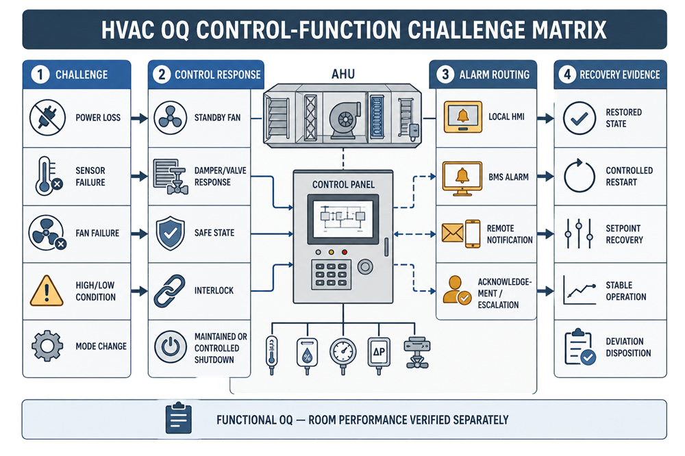
Purpose and Qualification Boundary
HVAC OQ determines whether the installed system responds correctly and predictably when its functions are operated or challenged.
Depending on system design and intended use, OQ may address:
- AHU startup, normal operation, shutdown, and restart
- Supply, return, relief, and exhaust-fan operation
- Fan status, speed control, proof of operation, and failure detection
- Outdoor-air, return-air, exhaust, isolation, and control dampers
- Heating, cooling, humidification, dehumidification, and reheat functions
- Temperature, relative-humidity, airflow, and pressure-control loops
- Normal, occupied, unoccupied, setback, cleaning, standby, and emergency modes
- High and low parameter limits
- Local and remote alarms
- Alarm delays, priorities, routing, acknowledgment, and escalation
- Equipment interlocks and permissives
- Duty-and-standby equipment changeover
- Utility-loss and power-loss responses
- Sensor, actuator, controller, drive, and communication failures
- Controlled shutdown and safe-state behavior
- Recovery following disturbances or failures
- Trend generation and event recording
- Building-management and environmental-monitoring interfaces
The scope should follow the approved system boundary and HVAC system architecture. Where control, monitoring, alarm, or data functions are tested under a separate automation package, the HVAC OQ should identify the interface, reference the accepted evidence, and verify that the combined test coverage is complete.
The protocol format does not determine the qualification phase. A combined IQ/OQ protocol may be acceptable, but installation checks and operational challenges must remain distinguishable.
Regulatory and Engineering Basis
21 CFR 211.46 requires adequate ventilation and, where appropriate, equipment for controlling air pressure, microorganisms, dust, humidity, and temperature. It also addresses air filtration, recirculation, exhaust, and separation of penicillin air-handling systems.
21 CFR 211.68 addresses automatic, mechanical, and electronic equipment, including routine calibration, inspection, or checking and appropriate controls over computer or related systems.
For aseptic-processing facilities, FDA’s Sterile Drug Products Produced by Aseptic Processing—Current Good Manufacturing Practice provides additional recommendations concerning HEPA-filtered air, pressure relationships, airflow, environmental control, monitoring, alarms, maintenance, and facility suitability.
These sources establish required controls and outcomes. They do not prescribe one universal HVAC OQ test list, control sequence, alarm delay, temperature range, humidity range, pressure differential, or recovery time.
OQ acceptance criteria must be derived from approved requirements, design intent, process needs, contamination-control or containment objectives, control sequences, operating procedures, and risk assessment.
Relationship Between HVAC OQ and Room-Performance Verification
HVAC functional OQ and room-performance verification are related but not interchangeable.
HVAC Functional OQ
Functional OQ determines whether the system:
- Starts and stops correctly
- Executes approved control sequences
- Maintains controller response within defined limits
- Modulates fans, dampers, valves, coils, and humidity equipment correctly
- Changes operating modes correctly
- Detects equipment and sensor failures
- Generates and routes alarms
- Executes interlocks and safe-state responses
- Records required values, states, alarms, and events
- Recovers correctly after a challenge or interruption
Room-Performance Verification
Room-performance verification determines whether the installed and operating system produces the required physical conditions in the served spaces.
This may include:
- Measured supply, return, transfer, and exhaust airflow
- Calculated air-change rates
- Installed HEPA-filter integrity
- Room differential pressures
- Airflow direction across doors and openings
- Temperature and humidity distribution
- Airflow visualization
- Recovery performance
- Cleanroom classification
- At-rest and in-operation environmental performance
A room-pressure control loop may be functionally challenged during OQ by changing a setpoint or simulating an input and confirming the controller response. That test does not, by itself, prove that the complete room pressure cascade is acceptable during door openings, exhaust changes, occupancy, or process operation.
Similarly, a temperature loop may achieve and maintain its control setpoint at the control sensor while unacceptable spatial variation remains elsewhere in the room.
OQ may include selected field measurements needed to demonstrate a control response. Final room acceptance should rely on the applicable airflow, filtration, and pressure verification and environmental-performance evidence.
OQ Prerequisites
OQ should begin only when the installed configuration is sufficiently complete, stable, and controlled to support meaningful functional testing.
Typical prerequisites include:
- Approved user requirements or equivalent requirement basis
- Approved system boundary and GMP-impact assessment
- Approved control narrative or sequence of operation
- Approved setpoint, alarm, interlock, and point lists
- Approved operating-mode definitions
- Accepted HVAC installation qualification
- Current as-built drawings and control diagrams
- Released control-system hardware and software configuration
- Completed startup and essential commissioning activities
- Current calibration for test and installed instruments
- Final or controlled filter configuration
- Completed initial testing, adjusting, and balancing sufficient to support OQ
- Required utilities available
- Alarm recipients and routing paths configured
- Applicable procedures available
- Defined safe methods for executing challenges
- Controlled management of open discrepancies
- Approved OQ protocol with predetermined acceptance criteria
If the control configuration is still changing, airflow balancing is incomplete, critical sensors are unavailable, or construction activities can disturb the system, the affected OQ testing should be deferred.
Testing an unstable configuration creates results that may not apply to the system ultimately released.
OQ Test Design
Each OQ test should identify:
- Requirement or risk being verified
- Function being challenged
- Initial system state
- Required operating mode
- Input, disturbance, or simulated failure
- Expected equipment and control response
- Expected alarm and interlock response
- Required data and trend records
- Acceptance criteria
- Permitted transient
- Required recovery condition
- Test instruments and calibration status
- Preconditions and safety controls
- Relationship to other qualification evidence
A functional test should demonstrate cause and effect. Merely observing that a fan runs, an alarm appears, or a displayed value changes does not establish that the complete intended function operates correctly.
Testing should verify the relevant path from the initiating condition through:
- Input detection
- Controller evaluation
- Commanded output
- Equipment response
- Status feedback
- Alarm or notification
- Recorded event
- Operator response, where applicable
- Recovery or safe-state completion
Control-Function Challenge Matrix
A control-function challenge matrix should connect each significant function or failure with its expected response and evidence.
| Challenge or condition | Expected control response | Alarm and notification | Recovery evidence |
|---|---|---|---|
| High temperature | Cooling response increases or defined backup action occurs | High-temperature alarm after approved delay | Temperature returns within the recovery criterion without unstable cycling |
| Low temperature | Heating response increases or cooling decreases | Low-temperature alarm after approved delay | Controlled recovery and stable operation |
| High relative humidity | Dehumidification or cooling/reheat sequence responds | High-humidity alarm routed to defined recipients | Humidity returns within the approved recovery criterion |
| Low relative humidity | Humidification sequence responds where installed | Low-humidity alarm routed as required | Stable recovery without condensation or overshoot |
| Low room pressure | Fan, damper, or airflow-control device responds according to sequence | Pressure alarm and required escalation occur | Required relationship is re-established and maintained |
| Supply-fan failure | Failure is detected; standby fan, shutdown, or safe-state sequence occurs | Fan-failure alarm is routed and recorded | Controlled restart or standby operation is demonstrated |
| Exhaust-fan failure | Supply and exhaust systems respond according to containment strategy | Exhaust-failure alarm and operational restriction occur | Containment condition is restored before release |
| Sensor failure | Invalid signal is detected; substitution, hold, shutdown, or safe state occurs | Sensor-failure alarm identifies the affected point | Correct value and control are restored after repair or reset |
| Power loss | Equipment enters the defined de-energized state | Power or communication-loss indication is generated where supported | Restart sequence, priorities, and stabilization are demonstrated |
| Network loss | Local control continues or system enters the approved state | Communication alarm occurs without false normal indication | Communication, data flow, and status indication recover correctly |
| Mode change | Fans, dampers, setpoints, alarms, and exhausts assume the approved mode | Mode status is displayed and recorded | Transition completes within the defined time |
| High filter differential pressure | Fan compensation or defined operational response occurs | Filter alarm is generated at the approved threshold | Response remains controlled and replacement requirements are clear |
The matrix should be system-specific. It should not assume that every HVAC system requires identical responses.
A positive-pressure product-protection area and a negative-pressure containment room may require opposite responses to the same fan, damper, or exhaust failure.
Startup, Shutdown, and Restart Sequences
OQ should verify the controlled sequence for normal startup and shutdown.
Startup testing may address:
- Required permissives before equipment starts
- Order and timing of supply, return, and exhaust fans
- Damper opening and proof requirements
- Utility availability
- Heating, cooling, and humidity-control enablement
- Variable-frequency-drive acceleration
- Airflow or pressure proof
- Alarm inhibition during legitimate startup delays
- Transition from startup to normal control
- Time required to achieve the defined stable operating state
- Prevention of premature room release
Shutdown testing may address:
- Normal operator-initiated shutdown
- Scheduled unoccupied-mode transition
- Emergency or protective shutdown
- Fan and damper sequence
- Utility-valve response
- Exhaust or containment requirements
- Alarm suppression or continued monitoring
- Prevention of uncontrolled pressure reversal
- Conditions required before restart
Automatic restart after power restoration should not be assumed to be desirable. The approved strategy may require automatic restart, sequenced restart, manual authorization, or continued shutdown depending on process, contamination, containment, equipment, and safety risks.
Fan Operation, Status, and Failure Challenges
OQ should verify each critical supply, return, relief, and exhaust-fan function.
Applicable tests may include:
- Start and stop commands
- Local and remote control
- Auto/manual selection
- Commanded status versus actual status
- Proof-of-flow, pressure, current, or auxiliary-contact indication
- Variable-speed response
- Minimum and maximum permitted speed
- Duty-and-standby designation
- Automatic standby-fan changeover
- Lead/lag rotation
- Failure detection
- Alarm generation
- Associated damper and interlock response
- Response of connected rooms or systems
- Restart following failure correction
A command signal stating that a fan is running is not independent proof of operation. The qualification strategy should define which feedback demonstrates actual fan operation and how a discrepancy between command and proof is handled.
Fan-failure challenges should be performed safely. Simulation at the controller or field-device level may be appropriate when intentionally stopping equipment would create unacceptable risk. The simulation method must demonstrate the intended logic without falsely claiming that an untested mechanical response was verified.
Dampers, Valves, and Actuators
Functional testing should verify the operation of applicable:
- Outdoor-air dampers
- Return-air dampers
- Exhaust and relief dampers
- Isolation dampers
- Pressure-control dampers
- Terminal airflow-control devices
- Heating and cooling valves
- Humidification valves
- Reheat valves
- Face-and-bypass arrangements
- Freeze-protection valves
- Associated position-feedback devices
Testing may include:
- Commanded opening and closing
- Modulating response
- Minimum and maximum positions
- Position feedback
- Mechanical or configured limits
- Fail-open, fail-closed, or fail-in-place response
- Response to loss of power or control signal
- Interlocks with fans, utilities, fire systems, or process equipment
- Alarm response when commanded and actual positions disagree
A displayed 100% command does not demonstrate that a damper or valve reached its physical position. Where position is critical, suitable feedback or direct observation should be used.
Temperature-Control Challenges
Temperature OQ should verify the functional control strategy rather than relying only on one stable reading.
Applicable testing may include:
- Approved setpoint entry and limits
- Response to a setpoint change
- Heating and cooling sequence
- Valve or staged-equipment response
- Deadband and changeover behavior
- High- and low-temperature alarm thresholds
- Alarm delay
- Control response near operating limits
- Sensor-failure response
- Loss of heating or cooling utility
- Reheat operation
- Trend accuracy and time sequence
- Recovery after a defined disturbance
- Prevention of excessive overshoot or unstable cycling
The challenge should remain within safe and justified conditions. OQ does not require deliberately exposing a room, product, or equipment to damaging extremes merely to activate an alarm.
Signal simulation, temporary alarm-limit adjustment under controlled conditions, or an approved test function may be used when direct environmental challenge is impractical. The method must demonstrate the intended logic and preserve the approved configuration after testing.
Room temperature mapping or spatial-distribution studies remain room-performance activities and should not be replaced by testing only the control sensor.
Humidity-Control Challenges
Humidity-control testing should consider that humidity loops can respond slowly and interact with temperature, cooling, reheat, outdoor-air conditions, and internal moisture loads.
Applicable tests may include:
- Humidity setpoint and permitted adjustment range
- Humidifier enablement and output response
- Dehumidification sequence
- Cooling and reheat coordination
- High- and low-humidity limits
- Alarm delay and routing
- Sensor-failure response
- Loss of steam, water, regeneration heat, or other supporting utility
- High-limit safety device
- Condensation-prevention interlock
- Recovery following a defined moisture or setpoint challenge
- Stability after recovery
- Prevention of simultaneous opposing control actions where prohibited
A simulated input may establish control-logic and alarm response. It does not establish that the installed system has sufficient moisture-removal or humidification capacity under the most demanding seasonal and operational loads.
Airflow and Static-Pressure Control
OQ may challenge airflow or duct-static-pressure control functions through:
- Airflow or static-pressure setpoint changes
- Variable-frequency-drive response
- Terminal-unit response
- Minimum and maximum control limits
- Filter-loading simulation or controlled increase in resistance
- Damper response
- Fan-tracking logic
- Supply-and-return or supply-and-exhaust coordination
- Low-airflow and high-static-pressure alarms
- Sensor-failure response
- Recovery following a disturbance
These tests establish whether the control loop responds as designed.
Final airflow quantities, diffuser distribution, return and exhaust balance, calculated air-change rates, and reconciliation against balancing records belong in detailed airflow, filtration, and pressure verification.
Room-Pressure Control and Pressure-Related Interlocks
Where room pressure is actively controlled, OQ should verify the functional response to defined pressure changes or simulated differential-pressure signals.
Testing may address:
- Pressure setpoint and adjustment restrictions
- Control direction
- Supply, return, exhaust, or damper response
- High- and low-pressure limits
- Alert and alarm delays
- Door-switch or airlock interlocks
- Response to a door held open
- Pressure-neutralization sequences
- Supply- or exhaust-fan failure
- Sensor failure
- Alarm suppression during approved transitions
- Recovery after doors close or equipment restarts
- Correct control response in each operating mode
The test must account for whether the room is intended for product protection, containment, or a justified combination of both. There is no universal safe pressure response.
OQ of the pressure-control function does not independently prove that the complete airflow and pressure cascade remains acceptable throughout all connected rooms, door conditions, local-exhaust states, and representative operations.
High and Low Limit Challenges
Critical limits should be challenged at or near the configured threshold using a safe and controlled method.
Testing should verify:
- Correct engineering units
- Correct high or low threshold
- Correct comparison logic
- Required deadband or hysteresis
- Approved time delay
- Alarm priority
- Alarm message and point identification
- Local display
- Remote routing
- Timestamp
- Acknowledgment requirements
- Return-to-normal behavior
- Latching or non-latching operation
- Required escalation
- Recorded alarm and event history
Qualification should distinguish:
- Control setpoint
- Normal control range
- Alert threshold
- Alarm or action threshold
- Equipment-protection trip
- Qualification acceptance criterion
Using one value for all functions without technical justification can create nuisance alarms, delayed detection, or inadequate operating margin.
Sensor Failure and Implausible-Signal Challenges
Critical sensor failures should not silently appear as valid normal conditions.
OQ should challenge applicable failure states, including:
- Open circuit
- Short circuit
- Loss of signal
- Out-of-range signal
- Frozen or unchanging value
- Implausible high or low value
- Disagreement between redundant sensors
- Communication loss
- Bad-quality status
- Sensor substitution or fallback value
The expected response may include:
- Alarm
- Transfer to a backup sensor
- Output held at the last safe value
- Output driven to a predetermined state
- Controlled shutdown
- Increased monitoring
- Restriction of manufacturing operation
- Operator assessment
A simulated sensor input verifies logic only to the point included in the simulation. If the field transmitter, wiring, input card, scaling, or communication path is bypassed, the protocol must identify which elements were and were not challenged.
Sensor-failure testing should also confirm that a failed or substituted value is clearly distinguishable from a valid measurement.
Power Loss and Electrical Recovery
Power-loss testing should address the actual power architecture and system risk.
Applicable challenges may include:
- Loss of normal power
- Transfer to emergency or standby power
- Loss of control power
- Loss of one electrical phase where detectable
- Variable-frequency-drive power interruption
- Controller reboot
- Loss of uninterruptible power supply
- Restoration of normal power
- Simultaneous restart demand
Testing should verify:
- De-energized position of fans, dampers, and valves
- Retention of configuration and setpoints
- Controller and network restart
- Alarm generation
- Correct time and event sequence
- Emergency-power loads
- Restart priorities
- Staggered equipment restart
- Manual or automatic restart requirements
- Prevention of uncontrolled pressure reversal
- Recovery of data collection and communication
- Return to the approved operating mode
A brief control-power interruption does not represent every possible facility power-loss condition. The protocol should define the extent of the test and any reliance on accepted electrical-system testing.
Utility Failure Challenges
HVAC performance may depend on:
- Chilled water
- Heating water
- Steam
- Clean steam
- Refrigeration
- Compressed air
- Desiccant-regeneration heat
- Electrical power
- Control power
- Network services
OQ should verify the approved response to loss or degradation of critical utilities.
The expected response may include:
- Alarm
- Valve repositioning
- Equipment shutdown
- Standby equipment start
- Freeze-protection action
- Continued ventilation without environmental control
- Restricted room use
- Process interruption
- Controlled shutdown
- Manual assessment before restart
The protocol should not assume that loss of temperature or humidity control requires immediate loss of airflow or pressure control. The required response depends on the system architecture and supported operation.
Occupied, Unoccupied, and Other Operating Modes
HVAC OQ should test every approved operating mode that changes a GMP-relevant function.
Modes may include:
- Occupied
- Unoccupied
- Production
- Nonproduction
- Cleaning
- Sanitation
- Setup
- Standby
- Reduced airflow
- Shutdown
- Maintenance
- Decontamination
- Emergency
- Fire or smoke response
- Utility-loss operation
Each mode should define:
- Fans operating
- Required airflow
- Damper positions
- Temperature and humidity setpoints
- Pressure relationships
- Exhaust operation
- Enabled and disabled alarms
- Alarm delays
- Monitoring status
- Permitted activities
- Transition method
- Required recovery before production
Testing should verify both the steady mode and the transition between modes.
An unoccupied or reduced-flow mode should not be accepted solely because the controls execute the command. The strategy must also establish that the mode does not create unacceptable contamination, containment, condensation, freezing, backflow, or recovery risk.
Interlocks and Permissives
Interlocks should be tested from the initiating condition through the final controlled response.
Applicable examples include:
- Fan start permitted only after damper opening
- Humidifier disabled without airflow proof
- Heating or cooling valve closed when the fan stops
- Electric heater disabled on low airflow
- Exhaust operation required before process-equipment operation
- Supply airflow reduced or stopped after exhaust failure
- Standby fan started after duty-fan failure
- Airlock doors prevented from opening simultaneously
- Decontamination mode preventing normal occupancy
- Freeze-stat trip closing outdoor air and opening heating service
- Smoke or fire signal commanding the approved HVAC state
- High condensate level stopping affected equipment
Testing should confirm:
- Initiating condition
- Logic state
- Commanded outputs
- Equipment response
- Status feedback
- Alarm
- Event record
- Reset requirements
- Recovery sequence
Interlocks should not be defeated during testing without approved controls, documented restoration, and verification that the released configuration is correct.
Alarm Routing, Notification, and Escalation
Generating an alarm at the controller does not demonstrate complete alarm delivery.
OQ should verify the required alarm path through applicable layers:
- Field device
- Controller
- Local panel or operator interface
- Building-management system
- Environmental-monitoring system
- Historian or event database
- Email, text, pager, or remote notification service
- Operator acknowledgment
- Escalation to additional recipients
- Return-to-normal notification
Testing should address:
- Correct point and condition
- Alarm message
- Priority
- Threshold
- Delay
- Timestamp
- Recipient or role
- Delivery route
- Acknowledgment
- Escalation time
- Latching behavior
- Return-to-normal behavior
- Alarm-history retention
- Response procedure
Alarm recipients should be verified by role or controlled distribution arrangement where individual personnel change frequently.
Testing should also confirm the response to notification-system or communication failure. An undelivered alarm should not remain indistinguishable from a successfully delivered alarm when the design requires delivery confirmation.
Detailed computerized-system and data functions may be tested through facility automation-system qualification, but HVAC OQ must retain traceability to the functions required for safe HVAC operation.
Trend, Display, and Data Verification
Where HVAC data support GMP operation, investigation, release, or continued verification, OQ should confirm applicable:
- Point identification
- Engineering units
- Scaling
- Displayed value
- Recording interval
- Timestamp
- Time synchronization
- Trend range
- Data continuity
- Alarm and event association
- Data retention
- Retrieval
- Report output
- Communication-failure indication
Comparison should be made against a suitable calibrated reference where accuracy of the recorded value is part of the intended use.
A point displayed correctly at one instant does not establish continuous data capture. Testing should evaluate the path from the field signal through storage and retrieval where that complete path is GMP-relevant.
Recovery Testing
Recovery in functional OQ means restoration of the HVAC system or control function after a defined disturbance.
It may include:
- Restart after power restoration
- Standby-fan takeover
- Restoration after sensor replacement
- Return from manual to automatic control
- Recovery after a high or low condition
- Recovery after a door-open disturbance
- Re-establishment of a control setpoint
- Return from unoccupied to occupied mode
- Restoration of communications
- Alarm clearance and return-to-normal recording
Acceptance criteria should define:
- Starting condition
- Disturbance
- Maximum permitted transient
- Required response
- Recovery endpoint
- Maximum recovery time
- Required stability period
- Alarm and event disposition
- Authorization required before resuming operation
Functional recovery should not be confused with cleanroom particle-recovery testing. Particle-recovery studies determine how quickly airborne-particle concentrations return to an acceptable level and belong to room-performance verification.
Seasonal Conditions and Capacity
Outdoor conditions can materially affect cooling, heating, humidification, dehumidification, outdoor-air treatment, pressurization, and system stability.
OQ planning should consider:
- Maximum summer temperature
- High outdoor moisture load
- Minimum winter temperature
- Low outdoor humidity
- Minimum and maximum outdoor-air positions
- Economizer operation
- Heating and cooling capacity
- Humidifier output
- Dehumidification and reheat
- Freeze protection
- Condensation risk
- Loaded-filter conditions
- Maximum occupancy and process heat load
- Simultaneous exhaust operation
- Utility-capacity limitations
Initial OQ performed during mild weather may verify control functions but may not demonstrate capacity at seasonal extremes.
Where direct seasonal testing is impractical, the qualification strategy may use:
- Approved design calculations
- Equipment-capacity data
- Commissioning results
- Controlled load challenges
- Automation trends
- Initial OQ data
- Deferred summer or winter verification
Deferred seasonal verification should have:
- Approved protocol or commitment
- Defined conditions that trigger execution
- Acceptance criteria
- Responsible owner
- Due date or seasonal window
- Interim operating controls
- Required response if criteria are not met
A seasonal commitment should not remain as an indefinite report comment after system release.
Use of Commissioning and Automation-Test Evidence
Commissioning and automation-test records may support OQ after documented assessment confirms that the evidence is suitable and applies to the final configuration.
Potential evidence includes:
- Startup and functional-performance tests
- Control-loop checks
- Point-to-point tests
- Alarm tests
- Interlock tests
- Functional sequence tests
- Fan and damper tests
- Duty-and-standby changeover tests
- Power-loss and restart tests
- Trend and communication tests
- Testing, adjusting, and balancing records
The assessment should determine:
- Requirement or risk addressed
- Tested system and configuration
- Test method
- Predetermined acceptance criteria
- Instrument suitability and calibration
- Raw-data availability
- Traceability
- Tester and reviewer qualification
- Deviation resolution
- Effect of subsequent changes
- Need for supplemental qualification testing
Commissioning origin does not make evidence automatically acceptable or unacceptable. The deciding issue is whether the record provides reliable, traceable evidence for the qualification requirement.
Acceptance Criteria and Data Evaluation
OQ acceptance criteria should be approved before execution and should distinguish:
- Commanded value
- Actual response
- Control tolerance
- Alarm threshold
- Alarm delay
- Equipment-protection limit
- Permitted transient
- Recovery time
- Stability period
- Measurement uncertainty
- Normal and challenge conditions
- Operating-mode-specific requirements
The final evaluation should consider technical consistency across related results.
Examples of inconsistent evidence include:
- A fan command indicates running while airflow proof remains absent
- A damper display indicates closed while downstream airflow continues unexpectedly
- A pressure loop responds correctly but connected rooms show an unexplained reversal
- An alarm appears locally but does not reach required recipients
- Temperature returns to setpoint but control output continues unstable cycling
- A standby fan starts but does not restore the necessary system condition
- A sensor-failure alarm occurs while the failed value remains displayed as valid
A collection of individual passing steps is not sufficient when the combined evidence shows an unresolved functional conflict.
Deviations and Failed Challenges
An OQ deviation should be documented when:
- An approved step is not executed as written
- An acceptance criterion is not met
- The configuration differs from the approved basis
- A challenge is not representative
- A simulation bypasses an element that was intended to be tested
- An instrument is unsuitable or outside calibration
- Data are missing, inconsistent, or unreliable
- The actual response differs from the approved sequence
- An unexpected condition affects the conclusion
The assessment should address:
- Failed function and affected requirement
- Initial condition and challenge
- Actual response
- Immediate correction or containment
- Technical or root cause
- Effect on completed and pending tests
- Effect on connected rooms or systems
- Effect on product protection or containment
- Need for expanded testing
- Corrective action
- Retest requirements
- Residual risk
- Final disposition
Repeating a challenge after configuration adjustment does not erase the initial failure. The original result, correction, configuration change, impact assessment, and retest must remain visible.
A passing retest establishes the response after correction. It does not prove that the earlier configuration was acceptable.
OQ Acceptance and Readiness for Room Verification
The OQ conclusion should determine whether the HVAC system functions are acceptable and whether the system is ready for applicable room-performance testing.
Acceptance should confirm, as applicable:
- Approved scope and functional boundaries were covered
- Required operating modes were tested
- Control loops respond correctly
- Setpoint restrictions and ranges are correct
- Fans, dampers, valves, coils, and humidity-control devices function as intended
- High and low limits were challenged
- Critical sensor failures were detected
- Power and utility-loss responses were tested
- Interlocks and safe-state behavior were accepted
- Alarm routing and escalation were demonstrated
- Trend and event records are reliable
- Recovery sequences were accepted
- Seasonal limitations and commitments are controlled
- Commissioning evidence was assessed before use
- Deviations were resolved or formally dispositioned
- Released configuration is identified
- Requirements and risks are traceable
- Remaining restrictions are clearly defined
OQ acceptance means that the installed system and controls function as intended within the tested operating envelope.
It does not mean that:
- HEPA-filter integrity has been demonstrated
- Final airflow balance has been accepted
- Every room pressure relationship has been established
- Airflow patterns protect critical locations
- Temperature or humidity is spatially uniform
- Cleanroom classification has passed
- In-operation environmental performance is acceptable
- Seasonal capacity has been proven when seasonal verification remains deferred
Those conclusions require the corresponding room and environmental evidence.
What HVAC OQ Explicitly Excludes
Unless a controlled integrated protocol assigns these activities to the OQ package with suitable methods and separate conclusions, functional HVAC OQ does not independently establish:
- Final testing, adjusting, and balancing acceptance
- Complete supply, return, transfer, and exhaust airflow verification
- Calculated room air-change rates
- Installed HEPA-filter integrity
- Airflow visualization or smoke-study acceptance
- Complete room-pressure-cascade acceptance
- Door-opening airflow-direction studies
- Temperature or humidity mapping
- Cleanroom classification
- Viable environmental performance
- In-operation contamination control
- Product protection during interventions
- Containment under representative process conditions
- Routine environmental-monitoring suitability
- Long-term performance or seasonal capacity not represented during testing
These activities may be scheduled within the broader OQ phase. Their placement in the project schedule does not make them control-function OQ tests.
Lifecycle Use of OQ Evidence
The accepted OQ package establishes the functional baseline for operation, maintenance, calibration, alarm management, change control, periodic review, and requalification.
Changes requiring assessment may include:
- Control-sequence modification
- Setpoint, alarm, delay, or interlock change
- Sensor replacement or relocation
- Instrument-range change
- Fan, motor, drive, damper, valve, or actuator replacement
- Heating, cooling, humidification, or dehumidification modification
- Operating-mode change
- Alarm-routing or recipient change
- Controller, software, firmware, or network change
- Power or emergency-power modification
- Exhaust or containment change
- Room-use, occupancy, or process-load change
- Seasonal operating restriction
- Repeated alarm, failure, or unstable-control trend
The response may range from a documented assessment to targeted functional testing, room-performance verification, or broader HVAC requalification.
Repeating every original OQ test is not automatically necessary. The scope should follow the affected functions, interfaces, risks, and previously accepted evidence.
Summary
HVAC operational qualification establishes that the installed HVAC system and its controls function correctly under defined normal, challenge, failure, and recovery conditions.
A complete HVAC OQ should:
- Define the functional boundary
- Distinguish control-function OQ from room-performance verification
- Challenge control loops and setpoints
- Verify fans, dampers, valves, coils, and humidity-control functions
- Test high and low limits
- Challenge sensor, fan, power, utility, and communication failures
- Verify occupied, unoccupied, and other approved modes
- Test interlocks and safe-state responses
- Confirm complete alarm routing and escalation
- Verify trend and event records where GMP-relevant
- Demonstrate controlled recovery
- Address seasonal limitations and deferred verification
- Use commissioning evidence only after documented assessment
- Preserve failures, corrections, and retest evidence
- Establish readiness for room-level verification
- Maintain traceability through lifecycle control
The objective is not to operate each device once and record a passing result. It is documented evidence that the HVAC system detects conditions, executes the approved response, communicates failures, and returns to a controlled state without creating an unresolved product-protection, containment, or operational risk.