

Cold Rooms and Walk-In Freezers: Design and Qualification
Cold rooms and walk-in freezers provide room-scale temperature-controlled storage for raw materials, intermediates, drug products, biological materials, laboratory supplies, retention samples, and other temperature-sensitive materials. Their performance depends on the integrated operation of the insulated enclosure, doors, refrigeration equipment, evaporators, airflow, controls, monitoring systems, alarms, storage configuration, operating procedures, and contingency arrangements.
Unlike self-contained pharmaceutical refrigerators and freezers, these systems are built into or installed within the facility and permit personnel entry. Their larger volume, distributed refrigeration components, longer airflow paths, pallet or shelving arrangements, penetrations, and frequent door access create qualification challenges that cannot be addressed by treating the room as an oversized refrigerator.
The required storage range must be established from the approved material, product, study, or process requirements. A refrigerated room is not automatically a 2–8 °C room, and a walk-in freezer is not universally required to operate between −15 and −25 °C. Design, qualification, monitoring, alarm limits, and contingency controls should be based on the approved intended use.
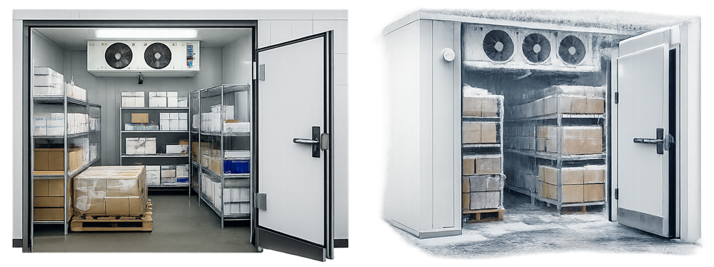
Cold rooms and walk-in freezers provide room-scale controlled storage using insulated enclosures, distributed refrigeration equipment, circulating airflow, fixed monitoring systems, and defined storage layouts.
Intended Use and System Boundary
The intended-use statement should establish:
- Materials or products to be stored
- Required temperature range
- Allowable operating variation
- Required storage capacity
- Expected pallet, rack, or shelving configuration
- Maximum storage height
- Minimum wall and ceiling clearances
- Maximum and minimum anticipated load
- Frequency and duration of personnel entry
- Frequency of material movement
- Required recovery performance
- Required local and remote alarms
- Continuous-monitoring requirements
- Emergency-power requirements
- Refrigeration redundancy
- Contingency-storage capacity
- Material-transfer requirements
- Required cleaning controls
- Personnel-safety requirements
- Expected ambient facility conditions
The system boundary should identify all components needed to maintain and demonstrate the controlled storage condition.
The boundary may include:
- Insulated wall, ceiling, and floor assemblies
- Doors, frames, seals, thresholds, and viewing panels
- Vapor barriers
- Panel joints and penetrations
- Refrigeration compressors
- Condensers
- Evaporators
- Expansion devices
- Refrigerant piping
- Defrost systems
- Condensate drains
- Circulation fans
- Temperature controllers
- Control sensors
- Independent monitoring sensors
- Local alarm devices
- Remote monitoring interfaces
- Electrical distribution
- Emergency-power interfaces
- Network connections
- Shelving and pallet racks
- Internal lighting
- Emergency-release mechanisms
- Associated procedures and contingency arrangements
The qualification boundary may include facility-owned and vendor-owned components. Responsibility for each component and interface should be defined before testing.
21 CFR 211.42 requires buildings used for manufacturing, processing, packing, or holding drug products to be suitably sized, constructed, and located to support cleaning, maintenance, and proper operations. 21 CFR 211.63 establishes corresponding expectations for equipment design, size, location, cleaning, and maintenance.
Insulated Enclosure Design
The enclosure limits heat transfer and moisture migration between the controlled room and the surrounding facility.
Cold rooms and walk-in freezers commonly use modular insulated panels with metal interior and exterior surfaces surrounding a polyurethane, polyisocyanurate, or other insulating core. The actual construction should be appropriate for the required temperature, fire rating, cleanability, traffic, moisture exposure, and installation environment.
Design assessment should address:
- Panel thickness
- Insulation type
- Thermal resistance
- Interior and exterior surface materials
- Panel-joint construction
- Floor insulation
- Ceiling support
- Structural loading
- Vapor-barrier location
- Door construction
- Window construction where provided
- Floor finish
- Impact protection
- Cleaning compatibility
- Penetration sealing
- Condensation prevention
- Repairability
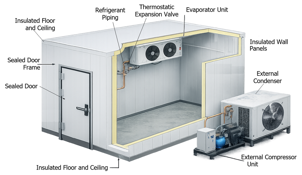
A controlled storage room depends on the combined integrity of insulated panels, sealed joints, doors, penetrations, vapor barriers, refrigeration equipment, and monitoring interfaces.
Vapor Barrier
The vapor barrier should be continuous across walls, ceiling, floor, doors, joints, and penetrations. Its location should reflect the expected direction of water-vapor migration.
A damaged or discontinuous vapor barrier can permit moisture to enter the insulation system. Potential consequences include:
- Condensation within panels
- Ice formation
- Reduced insulation performance
- Panel distortion
- Corrosion
- Mold or microbial growth in adjacent materials
- Frost around joints or penetrations
- Increased refrigeration load
- Progressive structural damage
Qualification cannot directly prove the long-term integrity of every concealed vapor-barrier surface. Design review, construction inspection, joint verification, pressure or leak testing where appropriate, thermographic assessment, and subsequent condition monitoring may provide supporting evidence.
Floor Construction
Walk-in freezer floors require particular attention because heat and moisture can enter from the supporting slab or adjacent structure.
Potential design features include:
- Insulated floor panels
- Subfloor vapor barrier
- Underfloor heating
- Heated glycol loops
- Electrical frost-protection systems
- Structural thermal breaks
- Slip-resistant internal finishes
Loss of underfloor frost protection can permit ice formation beneath the room, causing floor heaving, cracking, door misalignment, or structural damage. Where underfloor heating is critical, its operation, alarm, monitoring, and maintenance requirements should be included in the qualification strategy.
Doors, Seals, and Penetrations
Doors are major thermal and moisture boundaries.
Design features may include:
- Hinged or sliding doors
- Insulated door leaves
- Compressible perimeter gaskets
- Heated door frames
- Heated thresholds
- Automatic closers
- Door-position switches
- Door-open alarms
- Internal emergency-release mechanisms
- Vision panels
- Kick plates
- Impact protection
- Strip curtains or other infiltration controls
Verification should confirm:
- Correct door identity and construction
- Alignment
- Full closure
- Gasket contact
- Latching
- Automatic closing where specified
- Door-position indication
- Alarm initiation
- Heated-frame operation
- Internal emergency release
- Freedom from frost or ice that prevents closure
Penetrations for piping, electrical conduits, sensors, drains, sprinklers, lights, communication cables, or structural supports should be sealed appropriately. A penetration can create a thermal bridge, vapor leak, condensation point, or pathway for air infiltration.
A penetration should not be accepted solely because sealant is visually present. The installation should be assessed for continuity, adhesion, compatibility, low-temperature performance, cleanability, and movement.
Refrigeration-System Architecture
Room-scale systems typically use remotely located compressors and condensers connected to one or more evaporator units within the controlled room.
Major components may include:
- Compressors
- Condensers
- Receivers
- Expansion valves
- Evaporator coils
- Evaporator fans
- Refrigerant piping
- Oil-management components
- Pressure switches
- Temperature sensors
- Defrost heaters or valves
- Condensate drainage
- Controllers
- Motor starters or variable-frequency drives
- Safety devices
- Refrigerant leak detection where required
The architecture may use:
- One refrigeration circuit
- Multiple circuits
- Lead-lag compressors
- Staged capacity
- Duty-and-standby equipment
- Shared refrigeration infrastructure
- Dedicated systems
- Air-cooled condensers
- Water-cooled condensers
- Evaporative condensers
The presence of multiple compressors or evaporators does not automatically establish redundancy. The design assessment should determine what happens when each component fails.
Questions include:
- Can the remaining equipment maintain the approved storage range?
- Does the control system start the standby unit automatically?
- Is refrigeration capacity adequate at design ambient conditions?
- Are circuits truly independent?
- Do they share a common controller, condenser, power source, receiver, or refrigerant header?
- Will one failure disable multiple components?
- Is the remaining airflow adequate?
- How is failure detected and alarmed?
- How long can the room remain within limits?
A lead-lag arrangement may distribute runtime without providing full standby capacity. Redundancy claims should be supported by design information and functional testing.
Heat Loads and Design Capacity
The refrigeration system should be sized for the credible heat loads associated with intended operation. Heat loads may arise from:
- Transmission through walls, ceiling, and floor
- Door openings
- Air infiltration
- Incoming materials
- Personnel
- Lighting
- Fan motors
- Defrost heaters
- Material-handling equipment
- Adjacent facility conditions
- Solar or roof exposure
- Piping and electrical penetrations
- Product pull-down requirements
The design calculation should distinguish steady-state holding load from temporary pull-down or recovery load.
Incoming material can present a major thermal challenge. The room may be suitable for holding materials already at the required temperature but unsuitable for rapidly cooling large quantities of warm material. Qualification should not imply pull-down capability unless that function is part of the intended use and has been specifically evaluated.
Airflow Distribution
Evaporator fans circulate conditioned air through the room. The resulting temperature distribution depends on fan capacity, evaporator placement, discharge direction, return-air path, room geometry, storage arrangement, and operating state.
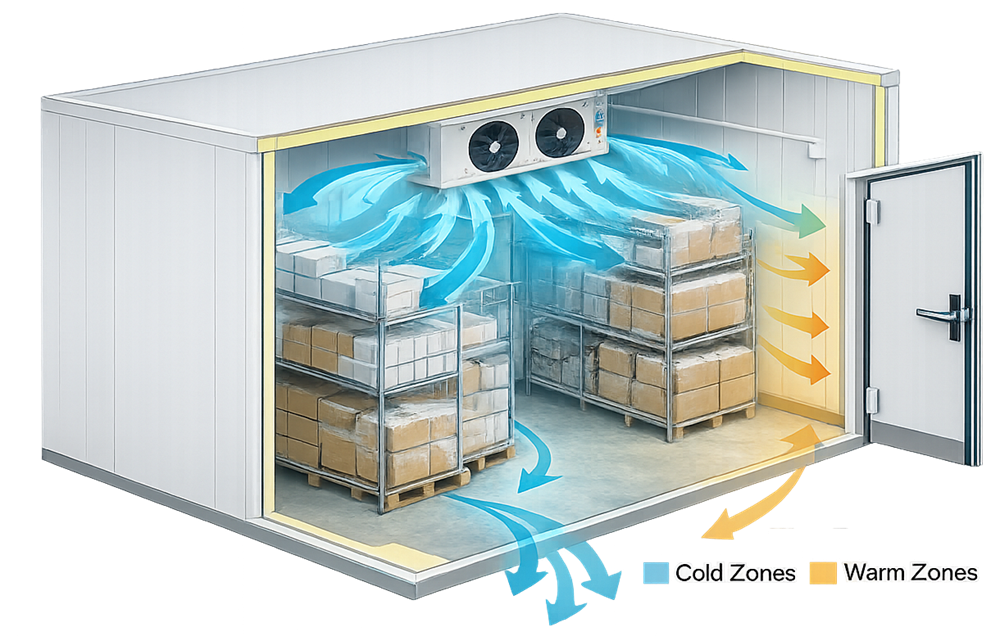
Cold-room airflow must travel around racks, shelving, pallets, stored materials, doors, and structural obstructions before returning to the evaporator. Potential temperature differences may occur:
- Near evaporator discharge
- Near evaporator return
- At the end of long aisles
- Behind densely loaded racks
- Near doors
- In corners
- At upper storage levels
- Near the floor
- Beneath or above solid shelving
- Between closely spaced pallets
- Near exterior walls or ceilings
- Near penetrations
- In areas shielded from circulation
Airflow can change when:
- Racks are installed or modified
- Pallet height changes
- Aisles are narrowed
- Temporary materials are staged
- Evaporator fans fail
- Frost accumulates
- Strip curtains are added
- Doors remain open
- The room is lightly loaded
- The room becomes densely loaded
Temperature uniformity should not be assumed from a design airflow pattern. It must be evaluated under defined operating and loading conditions.
Shelving, Pallet Racks, and Storage Configuration
Shelving and pallet racks are part of the qualified storage configuration when they materially affect airflow or define where materials may be stored.
Qualification and operating controls should define:
- Rack identity and layout
- Shelf type
- Shelf elevations
- Pallet positions
- Maximum pallet dimensions
- Maximum storage height
- Minimum ceiling clearance
- Minimum evaporator clearance
- Wall clearance
- Aisle width
- Prohibited storage zones
- Door-clearance zones
- Sensor-clearance zones
- Temporary-staging restrictions
- Floor-storage restrictions
- Maximum loading density
Wire shelving often permits greater airflow than solid shelving, but its use does not guarantee acceptable distribution. Pallets, boxes, insulated containers, shrink wrap, and large totes can still obstruct circulation.
A room should not be qualified using an idealized layout and then operated with materially different rack positions or loading patterns. The qualification report and routine procedure should use consistent storage-layout drawings.
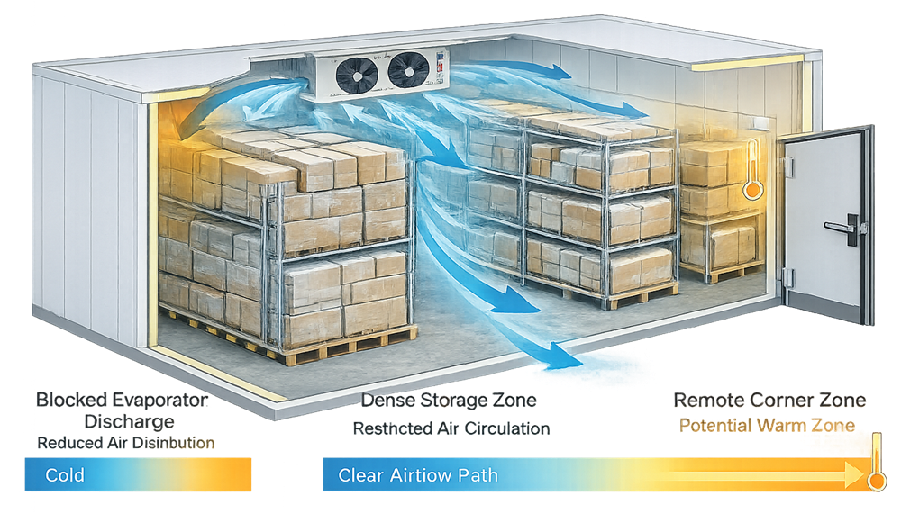
Storage layout can create cold locations near direct evaporator discharge and warmer locations behind dense loads, near doors, or in remote circulation zones.
Thermal mass can slow the temperature response during door openings or refrigeration failure. It does not correct an inadequate airflow path. A densely loaded room may remain thermally stable overall while still containing localized areas that do not meet acceptance criteria.
Condensation, Frost, and Ice
Moisture entering a refrigerated room may condense on cold surfaces. In a walk-in freezer, it may freeze on:
- Evaporator coils
- Fan guards
- Door frames
- Floors
- Ceilings
- Pipes
- Panel joints
- Stored materials
- Sprinkler components
- Monitoring probes
Potential consequences include:
- Reduced evaporator heat transfer
- Restricted airflow
- Blocked condensate drains
- Door-seal damage
- Inability to close the door
- Slip or trip hazards
- Ice falling from overhead surfaces
- Sensor response changes
- Packaging damage
- Increased defrost frequency
- Longer temperature recovery
Sources of moisture may include:
- Door openings
- Damaged seals
- Unsealed penetrations
- Wet cleaning
- Inadequate drainage
- Humid adjacent spaces
- Uncovered incoming materials
- Failure of door-frame heaters
Routine inspection should distinguish normal limited frost from progressive icing that indicates loss of control.
Defrost and Condensate Management
Evaporator frost can reduce airflow and heat-transfer efficiency. Defrost systems may use:
- Off-cycle defrost
- Electric heaters
- Hot-gas defrost
- Water defrost
- Manual defrost
- Manufacturer-specific methods
Defrost qualification should evaluate:
- Defrost initiation
- Frequency
- Duration
- Termination criterion
- Heater or hot-gas operation
- Fan operating state
- Drain-pan heating
- Condensate flow
- Drain-line heating
- Alarm inhibition
- Temperature response
- Recovery
- Operation with representative loading
- Restart after interrupted defrost
Rooms with multiple evaporators may defrost units sequentially to preserve cooling capacity and airflow. Qualification should verify the actual sequence and the system response if one evaporator remains in defrost longer than intended.
Alarm delays or inhibitions during defrost should be defined and tested. They should not mask an abnormal extended-defrost condition.
Condensate drains should be arranged to prevent freezing, blockage, leakage, backflow, or uncontrolled discharge. Drain heaters and traps should be included in maintenance and inspection where applicable.
Door Opening and Personnel Access
Opening the door creates air exchange between the controlled room and the surrounding facility. Warmer air generally enters through the upper portion of the opening while colder, denser air spills outward near the floor.
The effect depends on:
- Door size
- Opening duration
- Number of openings
- Traffic
- Ambient temperature
- Ambient humidity
- Room operating range
- Internal airflow
- Load configuration
- Thermal mass
- Use of strip curtains
- Use of air curtains
- Use of anterooms
- Material-handling practices
A door-opening challenge should represent a credible approved activity such as pallet movement, order picking, inventory access, or routine personnel entry.
The test should define:
- Initial stabilized condition
- Door used
- Door-opening duration
- Number of openings
- Simulated activity
- Load condition
- Ambient conditions
- Sensor locations
- Alarm response
- Recovery criterion
- Maximum acceptable recovery time
Recovery should not be based only on the controller display. Mapping locations and independent monitoring data should be evaluated as appropriate to the study objective.
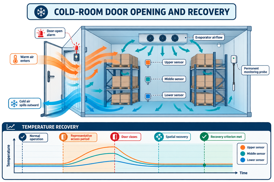
A representative door-opening challenge should evaluate air exchange, spatial temperature response, alarm behavior, and recovery throughout the qualified storage volume.
Strip curtains, air curtains, vestibules, or rapid doors may reduce infiltration, but their performance depends on installation and use. They may also obstruct movement, affect emergency egress, or alter airflow. Their effect should be included in qualification when they are part of the approved configuration.
Personnel Safety and Emergency Egress
Personnel-safety controls are not interchangeable with GMP product-protection controls. Both must be addressed.
Safety features may include:
- Internal emergency door release
- Emergency lighting
- Non-slip flooring
- Door-viewing panel
- Audible distress alarm
- Personnel-presence alarm
- Communication device
- Low-temperature protective equipment
- Ice-control procedures
- Safe shelving and pallet arrangements
- Refrigerant leak detection
- Oxygen monitoring where required by the refrigerant or system design
The internal door release should be tested from inside the room under representative conditions. Verification should address ice, frost, glove use, lighting loss, and any locking or access-control arrangement.
Door locking, badge access, or security controls must not prevent emergency egress.
Personnel-safety devices may be managed under facility safety programs rather than the GMP qualification package. The system boundary and responsibility should still be clear, particularly when a safety function can affect room access, refrigeration, alarms, or stored-material protection.
Control and Monitoring Architecture
The room controller regulates refrigeration operation using one or more control sensors. An independent monitoring system provides surveillance, alarm evidence, and records used for GMP decisions.
Control and monitoring functions may be separate or integrated, but their intended purposes and failure dependencies should be understood.
The architecture may include:
- Room control sensor
- Evaporator sensors
- Defrost-termination sensors
- Independent monitoring probes
- Local controller
- Building Management System
- Environmental Monitoring System
- Data historian
- Alarm server
- Notification service
- Network switches
- Local data buffering
- Backup power
- Time-synchronization service
The control sensor should not automatically be treated as representative of the entire storage volume. The independent monitoring location should be based on mapping results and the monitoring objective.
Potential monitoring locations include:
- A representative storage location
- A persistent warm location
- A location with slow recovery
- A critical storage zone
- A location susceptible to door effects
- Multiple locations where one probe cannot provide adequate surveillance
The absolute warmest point identified during one study is not automatically the best permanent monitoring location. The selected location should be accessible, protected from damage, representative of stored materials, stable across justified operating conditions, and capable of providing useful warning.
Detailed monitoring-system architecture, alarm logic, data buffering, electronic records, access control, and backup are addressed in Temperature Monitoring and Alarm Systems.
Alarm Strategy
Alarm settings should protect stored materials while avoiding delays or suppressions that conceal meaningful loss of control.
Potential alarms include:
- High room temperature
- Low room temperature
- Door open
- Refrigeration failure
- Compressor failure
- Evaporator-fan failure
- Defrost failure
- Sensor failure
- Communication failure
- Power failure
- Emergency-power failure
- Underfloor heating failure
- Monitoring-system failure
- Refrigerant leak
- Personnel distress
Alarm configuration should define:
- Initiating condition
- Setpoint
- Delay
- Deadband or hysteresis
- Priority
- Local annunciation
- Remote notification
- Escalation
- Acknowledgment
- Return-to-normal behavior
- Required response
- Event recording
Alarm testing should verify the entire response path rather than only the appearance of a message.
Testing may include:
- Create or simulate the initiating condition.
- Confirm detection by the correct sensor or device.
- Verify the configured delay.
- Verify local annunciation.
- Verify transmission to the monitoring system.
- Verify notification to the correct recipients.
- Verify acknowledgment and escalation.
- Verify event recording.
- Verify return-to-normal and reset behavior.
An alarm delay should be justified against equipment dynamics, normal operating disturbances, monitoring-probe response, stored-material risk, and required response time.
Qualification Strategy
Qualification should demonstrate that the installed room, refrigeration equipment, controls, monitoring system, alarms, storage configuration, procedures, and contingency arrangements collectively support the approved intended use.
The general qualification lifecycle is addressed in Validation Life Cycle. The cold-room-specific qualification strategy should address:
- Enclosure installation
- Refrigeration installation
- Control and monitoring architecture
- Airflow and temperature distribution
- Storage configuration
- Defrost
- Door access
- Alarm response
- Power interruption
- Refrigeration failure
- Emergency-power transfer
- Recovery
- Data integrity
- Contingency transfer
- Release
Vendor commissioning, Factory Acceptance Testing, and Site Acceptance Testing may support qualification when their scope, documentation, acceptance criteria, instruments, execution controls, and installed-configuration relevance are adequate. Vendor testing should not be accepted automatically as site qualification.
Design Review and Design Qualification
Design review should verify that the proposed room can meet the approved requirements before construction or purchase commitments are complete.
The review should address:
- Intended use
- Required range
- Storage capacity
- Room dimensions
- Qualified storage volume
- Panel construction
- Vapor barrier
- Floor design
- Door design
- Refrigeration capacity
- Design ambient conditions
- Heat-load calculation
- Pull-down requirements
- Refrigeration redundancy
- Evaporator arrangement
- Airflow pattern
- Defrost strategy
- Condensate drainage
- Shelving and rack layout
- Control sensors
- Independent monitoring sensors
- Alarm architecture
- Emergency power
- Material-transfer contingency
- Cleaning
- Maintenance access
- Personnel safety
- Refrigerant and environmental considerations
- Spare parts and vendor support
- Obsolescence
Design approval should not depend solely on nominal refrigeration capacity. The complete enclosure, load, airflow, access, monitoring, and failure strategy should be assessed.
Installation Qualification
Installation Qualification should confirm the as-built configuration.
Verification may include:
- Room identification
- Location
- Internal dimensions
- Panel type and thickness
- Wall, ceiling, and floor construction
- Panel joints
- Vapor-barrier records
- Door construction and orientation
- Door seals
- Heated frames and thresholds
- Emergency release
- Viewing panels
- Penetrations
- Lighting
- Drains
- Refrigeration components
- Refrigerant type and charge records where applicable
- Evaporator locations
- Fan identities
- Airflow direction
- Defrost components
- Temperature controllers
- Control sensors
- Monitoring sensors
- Local alarms
- Remote interfaces
- Electrical supply
- Emergency-power connection
- Network connection
- Shelving and rack layout
- Calibration status
- Software or firmware versions
- Drawings and manuals
- Preventive-maintenance requirements
- Spare-parts documentation
As-built drawings should reflect the installed room, refrigeration circuits, evaporators, sensors, alarms, electrical interfaces, rack layout, and storage boundaries.
Construction photographs and inspection records may provide important evidence for concealed insulation, vapor barriers, underfloor heating, joints, and penetrations.
Operational Qualification
Operational Qualification should challenge critical functions under controlled conditions.
Potential OQ tests include:
- Startup
- Initial pull-down
- Setpoint verification
- Controller accuracy
- Compressor staging
- Lead-lag operation
- Standby refrigeration
- Evaporator-fan operation
- Fan-failure response
- Defrost sequence
- Extended-defrost failure
- Condensate drainage
- Door-open alarm
- High-temperature alarm
- Low-temperature alarm
- Refrigeration-failure alarm
- Sensor failure
- Communication failure
- Power failure
- Emergency-power transfer
- Automatic restart
- Manual restart where required
- Controller recovery
- Access control
- Emergency release
- Electronic records
- Configuration security
- Backup and recovery
- Temperature mapping
- Door-opening recovery
21 CFR 211.68 requires automatic, mechanical, and electronic equipment to be routinely calibrated, inspected, or checked according to a written program designed to assure proper performance. Computerized functions supporting GMP records require appropriate controls, accuracy checks, and backup arrangements.
Three-Dimensional Temperature Mapping
Temperature mapping should characterize spatial and temporal conditions throughout the defined storage volume.
Cold rooms require three-dimensional consideration because temperature can vary:
- Across room length
- Across room width
- From floor to ceiling
- Between aisles
- Between open and obstructed locations
- Near exterior boundaries
- Near doors
- Near evaporators
- Behind racks
- Within remote corners
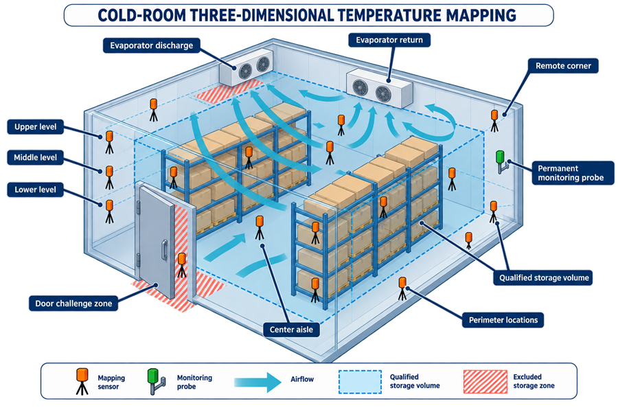
Three-dimensional mapping should represent the approved storage volume, vertical storage levels, doors, evaporators, racks, aisles, perimeter locations, and credible areas of reduced circulation.
Sensor count and placement should be justified according to:
- Room dimensions
- Geometry
- Rack configuration
- Evaporator arrangement
- Airflow
- Door locations
- Exterior boundaries
- Storage height
- Loading configuration
- Expected gradients
- Study objective
- Measurement uncertainty
No universal logger count applies to every room.
Mapping should capture relevant operating cycles, including compressor staging and defrost. A fixed study duration should not be selected without considering the system’s operating behavior and study objective.
General study design is addressed in Temperature Distribution and Qualification Strategy. Logger selection, calibration, response, sampling interval, drift, and measurement uncertainty are addressed in Thermal Mapping Instrumentation and Measurement Systems.
Empty, Loaded, and Representative-Load Studies
Empty mapping can characterize the inherent room and airflow performance without stored-material obstruction. It may also represent low thermal-mass conditions and help identify basic distribution problems.
Loaded or representative-load mapping evaluates:
- Routine rack and pallet configuration
- Airflow obstruction
- Storage density
- Vertical loading
- Material thermal mass
- Door-access practices
- Monitoring-probe suitability
- Recovery under representative use
Neither condition is universally sufficient by itself.
The qualification plan should determine whether the room requires:
- Empty mapping
- Representative-load mapping
- Maximum approved loading
- Minimum credible loading
- A challenging asymmetric load
- Multiple approved layouts
- Targeted studies at known difficult locations
A simulated load should represent relevant physical and thermal characteristics. Empty boxes may reproduce obstruction but not thermal mass. Water containers may provide thermal mass but may not represent frozen materials, palletized packaging, insulated shippers, or densely packed cartons.
Load diagrams should document:
- Rack identity
- Pallet locations
- Storage height
- Container type
- Load density
- Aisle condition
- Clearances
- Sensor positions
- Door-access route
- Prohibited storage areas
Seasonal Conditions
Seasonal mapping may be required when external weather or facility operating conditions can materially affect room performance.
Potential seasonal influences include:
- Outdoor condenser conditions
- Roof or exterior-wall exposure
- Facility ambient temperature
- Facility humidity
- Cooling-water temperature
- HVAC operating mode
- Door-infiltration conditions
- Loading patterns
- Defrost demand
Summer and winter do not automatically represent the worst conditions for every system. A high outdoor temperature may challenge condenser heat rejection, while a humid condition may create greater infiltration and frosting. A cold ambient condition may affect head-pressure control or other refrigeration functions.
The qualification strategy should determine:
- Whether seasonal effects are credible
- Which season or ambient condition is challenging
- Whether design data and commissioning evidence are sufficient
- Whether targeted seasonal mapping is required
- Whether routine trends provide supporting evidence
- Whether both summer and winter studies are justified
Seasonal qualification should be based on actual system dependencies, not on a universal calendar requirement.
Power-Loss and Refrigeration-Failure Testing
Power-loss testing and refrigeration-failure testing have related but different objectives.
Power loss may affect:
- Compressors
- Evaporator fans
- Controllers
- Monitoring systems
- Alarm transmission
- Lighting
- Door heaters
- Underfloor heating
- Network equipment
A refrigeration failure may occur while electrical power remains available. Monitoring, lighting, alarms, and fans may continue to operate while cooling capacity is lost.
Testing or documented simulation should address:
- Initial stabilized condition
- Load configuration
- Ambient conditions
- Failure introduced
- Alarm activation
- Remote notification
- Remaining refrigeration capacity
- Emergency-power transfer
- Controller restart
- Compressor restart delay
- Temperature holdover
- Recovery
- Material-transfer decision point
- Test-termination criterion
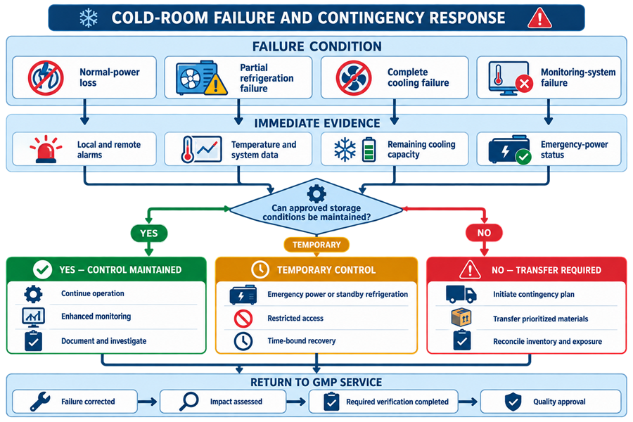
Qualification should distinguish loss of normal power, partial refrigeration failure, complete cooling failure, monitoring failure, and loss of emergency power because each condition can require a different response.
Failure testing should not create uncontrolled risk to GMP materials. Representative or simulated loads may be used.
The result should not be converted automatically into a universal allowable outage time. Actual holdover depends on room condition, ambient environment, load, access, remaining refrigeration capacity, and material thermal properties.
Performance Qualification
Performance Qualification should demonstrate acceptable operation under approved routine or simulated-use conditions.
The scope may include:
- Representative storage load
- Approved rack arrangement
- Routine personnel access
- Pallet movement
- Normal defrost sequences
- Compressor staging
- Independent monitoring
- Alarm response
- Trend review
- Execution by trained operators
- Contingency procedures
The number and duration of studies should be justified according to intended use, system variability, operating cycles, risk, and available design and OQ evidence.
A default requirement for three runs is not appropriate for every cold room. Repeat testing should provide meaningful evidence rather than satisfy an arbitrary number.
Acceptance Criteria and Data Evaluation
Acceptance criteria should be approved before execution and traceable to requirements.
Potential criteria include:
- The enclosure matches the approved design.
- Doors close and seal correctly.
- Penetrations are acceptably sealed.
- Refrigeration components operate as specified.
- Evaporator fans and defrost sequences operate correctly.
- Temperature remains within the approved criterion at required locations.
- The qualified storage volume is supported by mapping results.
- Defined load configurations are acceptable.
- Door-opening recovery meets the approved criterion.
- Alarm functions operate at approved settings.
- Notifications reach the correct recipients.
- Emergency-power transfer operates as intended.
- Failure response and recovery meet approved requirements.
- Electronic records are complete and retrievable.
- Required safety functions operate correctly.
- Contingency arrangements are available and effective.
Data evaluation should consider:
- Individual sensor results
- Spatial gradients
- Vertical stratification
- Temperature cycling
- Defrost events
- Compressor staging
- Door openings
- Recovery
- Sensor drift
- Missing data
- Measurement uncertainty
- Controller-to-reference differences
- Deviations
- Operating-state changes
Averages should not be used to conceal unacceptable individual locations. Mean kinetic temperature should not be used automatically to approve an unsuitable storage zone or dismiss an excursion.
Qualified Storage Volume
Mapping may demonstrate that some portions of the physical room cannot be used for storage.
Potential excluded areas include:
- Direct evaporator discharge
- Evaporator return path
- Areas immediately adjacent to doors
- Locations above approved storage height
- Areas close to walls or ceiling
- Floor areas
- Corners with poor circulation
- Locations around monitoring probes
- Fire-protection clearances
- Emergency-egress routes
- Temporary staging zones
The qualified storage volume should be defined through:
- Approved drawings
- Floor markings
- Rack labels
- Maximum-height indicators
- Physical barriers
- Operating procedures
- Training
An operator should be able to determine where storage is permitted without interpreting the complete mapping report.
Qualification Deviations and Release
Qualification deviations should be assessed for:
- Test validity
- Data integrity
- Effect on related tests
- Effect on the qualified storage volume
- Effect on alarm or monitoring strategy
- Effect on contingency response
- Root cause
- Corrective action
- Need for repeat testing
- Effect on release
A failed location should not be removed from the storage volume merely to avoid investigating the cause. Exclusion may be appropriate when the area was not intended for storage or when a technically justified permanent boundary is established. It should not replace correction of an actual system deficiency.
Release should occur only after:
- Required protocols are executed
- Deviations are resolved or acceptably dispositioned
- As-built documentation is approved
- Calibration is current
- Qualified storage boundaries are established
- Rack and loading configurations are approved
- Monitoring probes are installed
- Alarm settings are approved
- Contingency storage is available where required
- Procedures are effective
- Operators and alarm responders are trained
- The final report is approved
- Quality approval is obtained where required
Routine Operation and Continued Verification
Routine controls should maintain the qualified configuration.
Controls may include:
- Approved storage range
- Defined alarm limits
- Approved rack arrangement
- Storage-height limits
- Evaporator and wall clearances
- Door-opening practices
- Temporary-staging restrictions
- Continuous monitoring
- Daily or periodic data review
- Alarm response
- Excursion investigation
- Frost and ice inspection
- Door-seal inspection
- Evaporator inspection
- Condenser maintenance
- Defrost-system maintenance
- Drain inspection
- Calibration
- Emergency-power testing
- Contingency-storage verification
- Emergency-release testing
21 CFR 211.142 requires written warehousing procedures that include storage under appropriate temperature, humidity, and light conditions so that drug-product identity, strength, quality, and purity are not affected.
Trend review should evaluate:
- Temperature excursions
- Repeated short alarms
- Increasing recovery time
- Changing spatial differences
- Compressor runtime
- Compressor staging
- Fan failures
- Defrost duration
- Door-open frequency
- Frost or ice accumulation
- Sensor disagreement
- Communication failures
- Missing data
- Maintenance frequency
- Refrigerant repairs
- Emergency-power events
Cycle completion or return to normal temperature does not eliminate the need to assess repeated abnormal events.
Excursion and Contingency Response
A temperature excursion should trigger a documented response appropriate to the event and stored materials.
The assessment should address:
- Event start and end
- Maximum and minimum temperature
- Duration
- Affected room zones
- Stored materials
- Monitoring-data completeness
- Refrigeration status
- Door status
- Defrost status
- Power status
- Alarm history
- Notification and response time
- Immediate controls
- Material transfer
- Product or material impact
- Root cause
- Corrective action
- Qualification impact
The contingency plan should define:
- Alarm responders
- Escalation path
- Backup-room identity
- Available backup capacity
- Transfer decision criteria
- Material priority
- Required containers or carts
- Temperature control during transfer
- Inventory reconciliation
- Security and status segregation
- Documentation
- Authorization to return the original room to service
A backup room should not be considered available solely because it exists. Capacity, qualified range, monitoring, alarm status, access, and transfer logistics should be confirmed periodically.
Maintenance and Calibration
Maintenance should address components that can affect thermal control, monitoring, enclosure integrity, or personnel safety.
Potential activities include:
- Condenser cleaning
- Evaporator cleaning
- Fan inspection
- Compressor service
- Refrigerant-system inspection
- Leak testing
- Door adjustment
- Gasket inspection
- Heated-frame testing
- Defrost maintenance
- Drain cleaning
- Drain-heater testing
- Underfloor-heating testing
- Panel and joint inspection
- Penetration inspection
- Lighting maintenance
- Emergency-release testing
- Alarm testing
- Battery replacement
- Network-component maintenance
Calibration should address control, monitoring, alarm, and qualification instruments across their required operating ranges.
The program should define:
- Instrument identity
- Calibration range
- Calibration points
- Accuracy
- Tolerance
- Frequency
- Reference standards
- As-found result
- As-left result
- Adjustment
- Out-of-tolerance assessment
- Record retention
A control or monitoring sensor should not be calibrated only at room temperature when its required operating range is substantially different.
Change Control and Requalification
Potential changes include:
- Room expansion or reduction
- Panel repair
- Door replacement
- Gasket replacement
- New penetration
- Floor repair
- Rack relocation
- Shelf-height change
- Pallet-layout change
- Increased storage height
- Increased loading density
- Evaporator replacement
- Fan replacement
- Compressor replacement
- Refrigerant change
- Defrost change
- Controller replacement
- Control-sensor replacement
- Monitoring-sensor replacement
- Alarm-setting change
- Software or firmware update
- Monitoring-system change
- Emergency-power change
- Strip-curtain or air-curtain installation
- Change in intended use
- Change in operating range
- Extended shutdown
The impact assessment should determine whether existing evidence remains valid and whether additional verification is required.
Potential actions include:
- Documentation update
- Inspection
- Calibration
- Alarm testing
- Functional testing
- Airflow assessment
- Targeted mapping
- Door-opening recovery testing
- Defrost testing
- Failure testing
- Representative-load mapping
- Comprehensive requalification
A like-for-like classification should be based on technical comparison. Matching a general component description does not establish equivalence of capacity, airflow, range, accuracy, response, materials, control behavior, software, installation, or effect on temperature distribution.
Repeated excursions, slow recovery, increasing frost, sensor drift, repeated compressor repairs, loss of mapping records, or adverse trends can trigger requalification even when no formal design change occurred.
Risk-Based Requalification of GMP Equipment, Systems, and Utilities addresses the general decision process for targeted or comprehensive requalification.
Common Qualification Weaknesses
Common weaknesses include:
- Treating the room as an oversized refrigerator
- Assigning a universal operating range
- Failing to define the complete system boundary
- Accepting nominal refrigeration capacity without reviewing heat loads
- Assuming multiple compressors provide full redundancy
- Omitting vapor-barrier and penetration assessment
- Ignoring underfloor frost protection
- Mapping without the approved rack layout
- Using a universal logger count
- Mapping only at one vertical level
- Ignoring door and loading-dock effects
- Omitting defrost from the mapping period
- Assuming thermal mass corrects restricted airflow
- Using an unrepresentative empty-room study
- Failing to define the qualified storage volume
- Selecting monitoring-probe locations without mapping evidence
- Testing only local alarm indication
- Omitting emergency-power transfer and restart behavior
- Treating power loss and refrigeration failure as the same event
- Failing to test internal emergency release
- Using averages to conceal unacceptable locations
- Repeating failed tests without investigating the cause
- Changing racks or storage height without impact assessment
- Returning the room to service after major repair without verification
- Failing to maintain proven contingency-storage capacity
These weaknesses create gaps between room design, refrigeration performance, mapped storage conditions, monitoring, alarm response, routine loading, and material-protection decisions.
Conclusion
Cold-room and walk-in-freezer qualification should demonstrate more than the ability to reach a temperature setpoint. It should establish that the insulated enclosure, refrigeration equipment, evaporators, airflow, controls, monitoring system, alarms, storage layout, access practices, emergency power, and contingency arrangements collectively support the approved intended use.
A defensible qualification defines the system boundary and storage configuration, verifies installation, challenges normal and abnormal operation, maps the three-dimensional storage volume, evaluates door access, defrost, loading, power loss, and refrigeration failure, and establishes clear storage boundaries and release criteria.
Routine monitoring, alarm review, maintenance, calibration, excursion management, change control, and risk-based requalification then provide continuing evidence that the room remains suitable for controlled GMP storage.