

Liquid Nitrogen Cryogenic Storage: Design and Qualification
Liquid nitrogen cryogenic storage systems preserve cell banks, microbial cultures, tissues, biological samples, reference materials, and other temperature-sensitive materials at extremely low temperatures. Their suitability depends on more than the presence of liquid nitrogen. The vessel, storage configuration, liquid level, temperature distribution, sample location, filling system, monitoring, alarms, safety controls, procedures, and emergency arrangements must operate together.
Liquid nitrogen boils at approximately −196°C at normal atmospheric pressure. This does not mean every sample inside a cryogenic vessel remains at −196°C. Liquid-phase samples are exposed to conditions near the boiling point, while vapor-phase temperatures vary with height above the liquid, liquid level, vessel design, heat leakage, access frequency, rack configuration, and refill behavior.
Qualification should demonstrate that the defined storage zone remains within its approved conditions during normal operation and credible challenges. It should also verify that abnormal conditions are detected early enough to protect stored materials.
This article addresses equipment-specific design and qualification. General study design is addressed in Thermal Mapping Study Design and Qualification Strategy. Sensor selection, calibration, and uncertainty are addressed in Thermal Mapping Sensors, Data Loggers, and Measurement Uncertainty. Continuous monitoring and electronic records are addressed in Temperature Monitoring, Alarm Systems, and Data Integrity.
Intended Use and Storage Requirements
The intended use should be defined before selecting or qualifying a cryogenic storage system. Requirements should identify:
- Materials to be stored
- Required storage-temperature range
- Critical product or sample temperature
- Liquid-phase or vapor-phase operation
- Permitted storage locations within the vessel
- Maximum inventory
- Rack, canister, box, vial, or straw configurations
- Expected access frequency
- Maximum permitted access duration
- Manual or automatic filling
- Liquid-nitrogen supply arrangement
- Required monitoring parameters
- Alarm-response expectations
- Backup-vessel capacity
- Maximum acceptable transfer time
- Inventory and chain-of-custody requirements
- Electronic-record requirements
- Personnel-safety controls
The approved temperature requirement should be supported by material-specific stability, viability, development, or scientific information. Qualification should not substitute a generic cryogenic temperature for the actual storage requirement.
Very low temperatures substantially reduce biological and chemical activity, but statements that activity is completely halted should be avoided unless scientifically justified for the stored material.
Cryogenic Storage Vessel Design
Cryogenic storage vessels commonly use double-wall construction. The inner vessel contains the liquid nitrogen and storage assembly, while the outer shell provides mechanical protection. An evacuated space between the walls reduces conductive and convective heat transfer.
Multilayer reflective insulation may be installed within the vacuum space to reduce radiative heat transfer. The effectiveness of the vacuum and insulation influences:
- Static evaporation rate
- Nitrogen consumption
- Liquid-level stability
- Holdover time
- Temperature distribution
- Refill frequency
- Response to loss of supply
The vessel neck provides access to racks and samples but also represents an important heat-entry path. Neck geometry, lid construction, rack supports, access-port design, and sensor penetrations can affect the upper vapor-zone temperature.
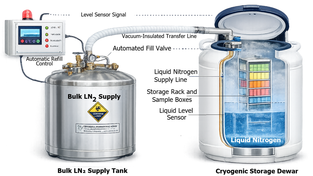
The following image shows representative cryogenic storage vessels.
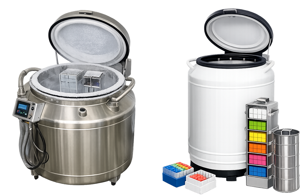
Cryogenic vessels may include:
- Removable racks or canisters
- Sample boxes and vial dividers
- Level sensors
- Temperature probes
- Automatic fill valves
- Vent and pressure-relief provisions
- Control and monitoring interfaces
- Local displays
- Remote alarm connections
- Inventory-identification systems
The vessel boundary, supply-system boundary, monitoring-system boundary, and facility-safety interfaces should be clearly defined during design review and qualification.
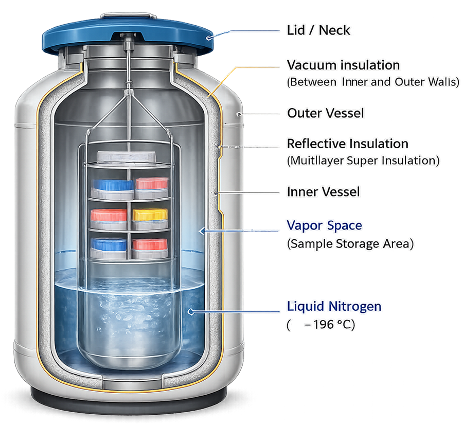
The cross-section should be verified against the installed vessel because internal supports, fill paths, sensor positions, and rack arrangements can differ between models.
Liquid-Phase and Vapor-Phase Storage
Cryogenic storage systems generally use liquid-phase storage, vapor-phase storage, or a defined combination of the two.
Liquid-Phase Storage
In liquid-phase storage, samples are submerged in liquid nitrogen. This configuration provides temperatures close to the boiling point of liquid nitrogen and generally limits vertical temperature variation.
The assessment should address:
- Container compatibility with immersion
- Seal integrity
- Liquid ingress into containers
- Container rupture during warming
- Handling of submerged racks
- Sample retrieval
- Potential contamination of the shared liquid phase
- Personnel exposure during access
Liquid-phase storage should not be described as inherently contamination-free. The risk depends on container integrity, sample type, handling practices, nitrogen quality, and the intended use of the stored materials.
Vapor-Phase Storage
In vapor-phase storage, samples remain above the liquid surface in cold nitrogen vapor. This reduces direct contact between samples and the liquid phase but introduces greater dependence on:
- Minimum liquid level
- Vertical sample position
- Distance from the liquid surface
- Vessel neck and lid performance
- Rack configuration
- Access duration
- Refill behavior
- Vapor circulation
The upper part of the storage zone may represent the most challenging temperature location. That location should be determined by mapping rather than assumed from the vessel drawing.
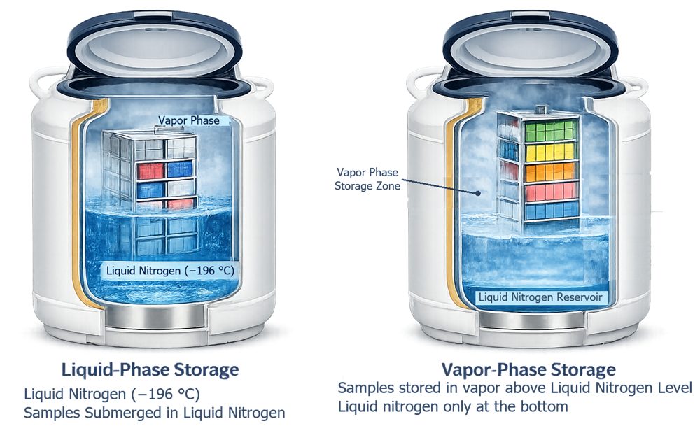
Selection between liquid- and vapor-phase storage should be based on the stored material, container system, contamination-control strategy, required temperature, operational practices, and risk assessment.
Rack Configuration and Inventory Control
Racks, canisters, boxes, dividers, and sample containers form part of the qualified storage configuration.
Qualification should confirm:
- Rack identity and dimensions
- Compatibility with the vessel
- Defined rack positions
- Maximum permitted storage height
- Sample-box compatibility
- Mechanical stability
- Retrieval without uncontrolled warming
- Prevention of obstruction to filling or venting
- Compatibility with level and temperature sensors
- Legible position identification
- Inventory-system alignment
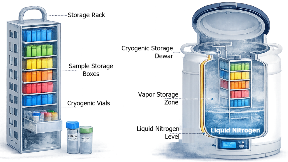
Inventory location should be traceable to the vessel, rack, vertical position, box, and sample location where required. This traceability supports targeted assessment when an excursion affects only part of the qualified storage zone.
Uncontrolled changes in rack type, storage height, inventory density, or box configuration can alter thermal behavior and should be assessed before implementation.
Liquid-Nitrogen Supply and Automatic Filling
Liquid nitrogen is continuously lost through normal evaporation. The system must replenish this inventory before the storage zone approaches an unacceptable condition.
Supply arrangements may include:
- Manual filling from portable dewars
- Connection to a dedicated supply vessel
- Distribution from a central bulk-storage system
- Automatic filling through vacuum-jacketed transfer lines
- Redundant or alternate supply arrangements
An automatic fill system commonly uses a level sensor, controller, fill valve, and defined start and stop conditions. Qualification should challenge the complete control path rather than merely demonstrate that the valve can open.
Testing should address:
- Low-level fill initiation
- Upper-level fill termination
- Fill duration
- Fill timeout
- Valve fail-open behavior
- Valve fail-closed behavior
- Interrupted fill
- Insufficient supply pressure
- Empty or isolated supply source
- Transfer-line leakage or excessive heat gain
- Sensor failure
- Overfill prevention
- Manual-fill operation
- Venting during filling
- Alarm and notification generation
- Recorded fill events
Cryogenic liquid must not be trapped between closed valves without appropriate pressure relief. Any trapped liquid can generate substantial pressure as it warms and expands.
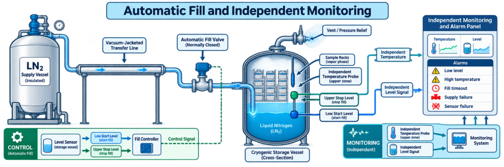
The filling controller and independent monitoring system may share components only when the resulting common-mode failure has been assessed. A control indication should not automatically be accepted as independent evidence that the storage condition remained acceptable.
Liquid Level and Temperature as Linked Conditions
Liquid level and storage-zone temperature are related but distinct parameters.
Liquid level provides early information about the remaining cooling inventory and refill status. Temperature demonstrates the thermal condition at the probe location. Neither measurement alone proves that the complete storage zone remains controlled.
A system can have:
- An acceptable liquid level but an abnormal upper-zone temperature
- A normal displayed temperature while the liquid supply is being depleted
- An apparently stable temperature during a failed level measurement
- A normal controller display during a monitoring-system failure
- Localized warming that is not detected by a poorly positioned probe
Critical installations should therefore consider independent level and temperature monitoring, with sensor locations supported by qualification data.
Temperature Distribution and Vapor-Zone Mapping
Cryogenic-vessel mapping differs from conventional refrigerator or room mapping. A rectangular grid may not represent the actual rack positions, vertical gradients, vessel geometry, or liquid-level dependency.
The study should define:
- Qualified storage-zone boundary
- Liquid- or vapor-phase configuration
- Minimum normal liquid level
- Representative or maximum approved rack configuration
- Normal inventory distribution
- Sensor locations at relevant vertical positions
- Central and peripheral locations
- Upper storage locations near the neck
- Access and rack-removal challenges
- Automatic refill cycles
- Stabilization and recovery
- Data-acquisition interval
- Sensor range and response
- Acceptance criteria
- Treatment of measurement uncertainty
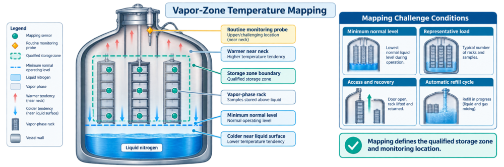
Mapping should evaluate credible normal and challenging conditions. Potential challenges include:
- Minimum normal operating level
- Representative inventory
- Maximum approved storage height
- Routine lid opening
- Extended but permitted access
- Rack removal and replacement
- Automatic filling
- Manual filling
- Short supply interruption
- Recovery following access
The required number of sensors, study duration, and number of runs should be justified. No universal configuration applies to every vessel.
Mapping results should define the approved storage zone and support routine monitoring-probe placement. A probe should not be placed only where it is convenient or where temperatures are expected to be coldest.
Monitoring and Alarm Systems
Monitoring should provide timely detection of conditions capable of compromising stored materials. Potential monitored parameters include:
- Storage-zone temperature
- Liquid-nitrogen level
- Fill status
- Fill duration
- Supply pressure or availability
- Valve status
- Controller condition
- Sensor condition
- Power availability
- Communication status
- Ambient oxygen concentration
Product-protection alarms may include:
- High storage-zone temperature
- Low liquid level
- Critically low liquid level
- Fill timeout
- Supply failure
- Valve failure
- Temperature-sensor failure
- Level-sensor failure
- Monitoring communication failure
- Power failure
- Missing data
Alarm setpoints and delays should be based on system behavior, material risk, normal access and filling events, response time, and remaining holdover. Delays should prevent nuisance alarms without allowing a meaningful failure to remain undetected.
Testing should verify the complete alarm path: Condition → Detection → Recorded Alarm → Local Indication → Remote Notification → Acknowledgment → Escalation → Response → Closure
Electronic records, access controls, time synchronization, audit trails, backup, and recovery should be addressed according to the intended use of the monitoring system and the principles in FDA’s Data Integrity and Compliance With Drug CGMP guidance.
Oxygen-Deficiency and Personnel-Safety Controls
Nitrogen gas can displace oxygen when liquid nitrogen evaporates. OSHA defines an oxygen-deficient atmosphere as containing less than 19.5 percent oxygen by volume. This definition does not establish a universal alarm design for every cryogenic room; the complete facility hazard assessment remains necessary. Safety controls may include:
- Room-volume assessment
- Maximum credible nitrogen release
- Normal and emergency ventilation
- Fixed oxygen monitors
- Audible and visual alarms
- Alarm indication outside the room
- Emergency egress
- Restricted entry after an alarm
- Vent and pressure-relief discharge routing
- Cryogenic gloves and face protection
- Procedures for spills and supply-line failures
- Training
- Inspection and calibration of oxygen monitors
Oxygen-sensor placement should be based on the room, release sources, air movement, ventilation, obstructions, and the behavior of nitrogen as it warms and mixes. A simplistic rule that every sensor must be mounted at one fixed height is not sufficient.
Product-protection monitoring and personnel-safety monitoring have different objectives. Both may be required, but successful temperature monitoring does not demonstrate that the room is safe for entry.
Calibration at Cryogenic Temperatures
Calibration at cryogenic temperatures requires specific consideration because conventional calibration arrangements may not represent the installed measurement condition.
The calibration strategy should address:
- Sensor technology
- Required measurement range
- Calibration points
- Reference-standard suitability
- Traceability
- Immersion depth
- Thermal equilibrium
- Lead-wire effects
- Sensor self-heating
- Installation configuration
- Display or transmitter contribution
- Measurement uncertainty
- As-found and as-left results
- Drift assessment
- Failed-calibration impact
A room-temperature calibration alone may be insufficient when the sensor’s critical use is at cryogenic temperature. Conversely, an exact −196°C calibration point should not be required without considering the approved storage range, available standards, uncertainty, and sensor performance.
Functional verification can confirm alarm or display operation, but it is not automatically equivalent to calibration.
Installation Qualification
Installation Qualification should verify that the installed system conforms to approved requirements and design documentation.
IQ may include:
- Manufacturer, model, and serial number
- Vessel capacity and configuration
- Liquid- or vapor-phase intended use
- Vessel and vacuum integrity documentation
- Rack and inventory configuration
- Liquid-nitrogen supply source
- Transfer-line routing and insulation
- Automatic fill valve
- Pressure-relief and vent paths
- Level sensors
- Temperature sensors
- Monitoring-system connections
- Alarm interfaces
- Power supplies
- Network connections
- Oxygen monitoring
- Room ventilation
- Equipment labels
- Drawings and manuals
- Material and component certificates where applicable
- Calibration status
- Preventive-maintenance requirements
- Approved procedures
The installed arrangement should be compared with approved drawings. Documentation should identify the precise system boundary and interfaces with facility utilities, safety systems, monitoring systems, and inventory systems.
Operational Qualification
Operational Qualification should demonstrate operation throughout the approved range and challenge credible abnormal conditions.
OQ may include:
- Level indication
- Low-level and critically low-level alarms
- Automatic fill initiation and termination
- Fill timeout
- Manual filling
- Supply interruption
- Valve failure response
- Temperature indication
- High-temperature alarm
- Sensor disconnection or failure
- Communication failure
- Power interruption
- Data buffering and recovery
- Local and remote alarm notification
- Alarm acknowledgment and escalation
- User access and audit trails
- Oxygen-monitor alarm and ventilation response
- Recovery after access
- Aborted or incomplete fill-event status
Testing should verify the required response, not only the appearance of an alarm message. For example, a fill-timeout test should confirm valve response, recorded status, notification, escalation, and recovery controls.
Performance Qualification
Performance Qualification should demonstrate that the vessel, supply, racks, inventory configuration, monitoring, procedures, and operators perform together under representative conditions.
PQ may include:
- Representative or challenging inventory
- Minimum normal liquid level
- Defined storage-zone mapping
- Temperature distribution
- Normal refill cycles
- Routine access
- Recovery after rack retrieval
- Nitrogen-consumption or boil-off evaluation
- Monitoring-probe suitability
- Alarm-response execution
- Operator response
- Backup-vessel readiness
- Inventory traceability
- Repeatability
PQ should use physically representative conditions. A deliberately invalid rack arrangement or an access period prohibited by procedure does not demonstrate routine performance.
The number of runs should be justified using risk, system variability, development information, previous testing, and intended use rather than an assumed universal convention.
Failure Response and Emergency Transfer
An approved response plan should be available before the system is released for routine use.
Potential initiating conditions include:
- Low liquid level
- High storage-zone temperature
- Failed automatic fill
- Depleted supply
- Transfer-line failure
- Level-sensor failure
- Temperature-sensor failure
- Monitoring-system failure
- Vessel damage
- Loss of vacuum
- Extended power or communication loss
- Oxygen-deficiency alarm
The initial assessment should review verified temperature and level data, alarm duration, remaining holdover, affected inventory positions, availability of manual filling, and readiness of the backup vessel.
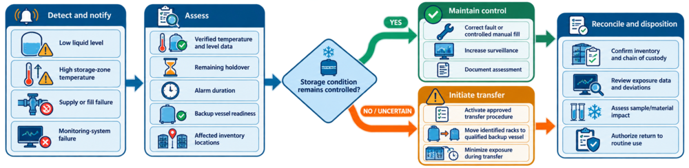
When the storage condition cannot be confirmed or maintained, the approved transfer procedure should define:
- Decision authority
- Qualified backup-vessel capacity
- Transfer priority
- Rack and sample identification
- Required personnel
- Cryogenic handling controls
- Maximum exposure during transfer
- Chain of custody
- Inventory reconciliation
- Temperature-data review
- Deviation documentation
- Material-impact assessment
- Return-to-service authorization
A backup vessel is not a meaningful contingency unless it has adequate capacity, remains qualified, is supplied with liquid nitrogen, and can receive the affected inventory within the required time.
Routine Operation and Continued Verification
Routine controls should confirm that the system remains in its approved operating state.
Reviews may include:
- Storage-zone temperature
- Liquid-nitrogen level
- Refill frequency and duration
- Nitrogen consumption
- Alarm history
- Communication failures
- Sensor status
- Power interruptions
- Inventory loading
- Access events
- Backup-vessel availability
- Calibration status
- Preventive maintenance
- Oxygen-monitor status
- Ventilation condition
- Open deviations
Changes in nitrogen consumption or refill frequency can provide early evidence of vacuum degradation, supply problems, valve leakage, changing access patterns, or altered operating conditions.
Alarm trends should be reviewed rather than treating each alarm as an isolated event.
Maintenance and Inspection
Maintenance should address components that can affect storage control or safety.
Potential activities include:
- Vessel inspection
- Lid and neck inspection
- Vacuum-performance assessment
- Static evaporation or consumption review
- Transfer-line inspection
- Fill-valve testing
- Pressure-relief inspection
- Level-sensor maintenance
- Temperature-sensor calibration
- Alarm testing
- Battery replacement
- Monitoring-system backup
- Oxygen-monitor calibration
- Ventilation testing
- Rack and handle inspection
Maintenance that affects the vessel, fill path, sensors, racks, monitoring configuration, or thermal performance should be evaluated before return to use.
Change Control and Requalification
Potentially significant changes include:
- New material or sample family
- Changed storage-temperature requirement
- Liquid-phase to vapor-phase operation
- Changed qualified storage zone
- New rack, box, or canister design
- Increased storage height
- Changed inventory density
- Vessel relocation
- Fill-valve replacement
- Level-sensor replacement
- Temperature-probe replacement or relocation
- Supply-source change
- Transfer-line modification
- Monitoring-system change
- Alarm-setting change
- Software or network change
- Ventilation modification
- Major vessel repair
- Extended shutdown
- Loss of vacuum
- Repeated temperature or level alarms
The assessment should determine whether existing evidence remains applicable and whether targeted or comprehensive requalification is required.
Potential requalification activities include:
- Installation verification
- Calibration
- Automatic-fill testing
- Alarm testing
- Temperature mapping
- Access-and-recovery testing
- Monitoring-probe confirmation
- Communication-failure testing
- Emergency-transfer verification
The rationale should identify both the tests selected for repetition and those not repeated. Broader trigger-to-scope decisions are addressed in Risk-Based Requalification of GMP Equipment, Systems, and Utilities.
Acceptance Criteria and Deviations
Acceptance criteria should be approved before execution and should be specific to the installed system.
Examples include:
- Installed components match approved drawings.
- The defined storage zone remains within its approved temperature limits.
- The minimum normal liquid level supports the qualified vapor zone.
- Automatic filling starts and stops at approved conditions.
- Fill timeout produces the required protective response.
- High-temperature and low-level alarms follow the approved notification path.
- Sensor and communication failures are detected.
- Required records are complete and retrievable.
- Access recovery meets the approved criterion.
- Backup capacity and transfer arrangements remain available.
- Personnel-safety alarms and ventilation responses meet approved requirements.
Deviations should be assessed for test validity, stored-material impact, related testing, root cause, corrective action, repeat testing, and qualification status.
Testing should not be repeated solely to obtain a passing result.
Common Qualification Weaknesses
Common weaknesses include:
- Treating the presence of liquid nitrogen as proof of acceptable storage
- Assuming all samples remain at −196°C
- Failing to define the qualified storage zone
- Qualifying an empty vessel without representative racks
- Ignoring the minimum normal liquid level
- Monitoring temperature without monitoring level
- Monitoring level without verifying vapor-zone temperature
- Placing the routine probe without mapping evidence
- Testing the fill valve without challenging supply or sensor failure
- Omitting fill-timeout and overfill response
- Treating controller data as independent monitoring
- Using room-temperature calibration for an unassessed cryogenic application
- Ignoring upper-zone temperature gradients
- Failing to test access and recovery
- Maintaining a backup vessel without verified capacity
- Omitting inventory reconciliation from emergency transfer
- Confusing product-protection monitoring with oxygen-safety monitoring
- Repeating qualification only by calendar rather than assessing changes and trends
Conclusion
Liquid nitrogen cryogenic storage qualification should establish control of the complete storage system, not merely verify that the vessel contains liquid nitrogen.
A defensible qualification defines the approved storage zone, distinguishes liquid- and vapor-phase operation, verifies the relationship between liquid level and temperature, challenges automatic filling and credible failures, establishes monitoring and alarm performance, evaluates cryogenic calibration limitations, and confirms emergency-transfer capability.
Routine review of temperature, level, refill behavior, alarms, inventory configuration, maintenance, calibration, oxygen-safety controls, changes, and adverse trends then provides continuing evidence that the cryogenic storage system remains suitable for its intended use.