

Dissolution Apparatus Qualification and Lifecycle Control
Dissolution apparatuses create controlled hydrodynamic and thermal conditions for measuring drug release from tablets, capsules, and other dosage forms. Although the final concentration may be measured by UV-Vis spectroscopy, HPLC, or another analytical technique, the dissolution apparatus determines the physical conditions under which the dosage form releases the drug substance.
Small differences in vessel geometry, shaft alignment, paddle or basket position, rotational speed, temperature, vibration, sampling location, or medium preparation can affect the observed dissolution profile. Qualification must therefore address the physical apparatus, sampling system, control software, analytical interface, and continued control of components that influence the test environment.
This article focuses primarily on USP Apparatus 1, the rotating basket, and USP Apparatus 2, the rotating paddle. These are the configurations most commonly used for dissolution testing of immediate-release and modified-release solid oral dosage forms. The same lifecycle principles apply to other dissolution and drug-release apparatuses, but their specific mechanical and operational requirements must be addressed separately.
Purpose and Qualification Objectives
Dissolution apparatus qualification should demonstrate, as applicable, that:
- the installed configuration matches the approved intended use
- vessels, shafts, paddles, baskets, and related components conform to applicable requirements
- vessel position and tool alignment are controlled
- shafts are centered and vertical
- paddles and baskets are positioned at the required height
- rotational speed is accurate and stable
- shaft wobble and runout remain acceptable
- basket condition and rotational characteristics are suitable
- vessel temperature is accurate and sufficiently uniform
- timers and programmed operating periods are accurate
- vibration and environmental influences are controlled
- manual or automated sampling occurs at the correct position and time
- sample withdrawal, filtration, transfer, and volume replacement are controlled
- communication with UV-Vis, HPLC, or another analytical system is reliable
- calculations and electronic records remain complete and accurate
- mechanical qualification and performance verification are scientifically integrated
- routine checks and maintenance sustain continued fitness for use
- changes, failures, and component replacements receive proportionate assessment and verification
Qualification depth should follow the approved risk-based analytical instrument qualification strategy and the system’s analytical instrument risk classification.
Dissolution System Architecture
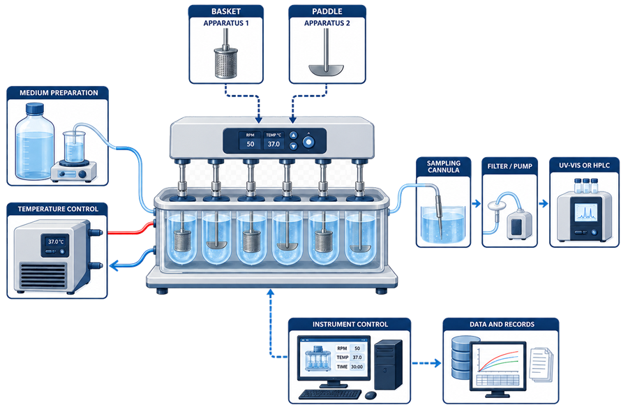
A conventional dissolution system may include:
- six, seven, eight, or more vessel positions
- glass or other qualified vessels
- vessel covers
- rotating shafts
- interchangeable paddles or baskets
- drive head and motor
- speed-control system
- water bath or individual vessel heaters
- temperature sensors
- external circulator or heater
- timer and sequence controls
- manual or automated dosage-delivery mechanism
- sampling cannulas
- sampling manifolds
- filters
- tubing
- pumps
- fraction collector
- medium-replacement system
- control workstation
- dissolution software
- UV-Vis or HPLC interface
- electronic-record storage
- network and backup services
The qualified boundary depends on intended use. A manually operated apparatus with offline UV-Vis testing has a different boundary from a fully automated system that introduces dosage units, withdraws and filters samples, replaces medium, performs online UV measurements, calculates results, and transfers records to LIMS.
The following illustration shows the principal dissolution apparatus functions and the sample path to the analytical finish.
USP Apparatus Configurations
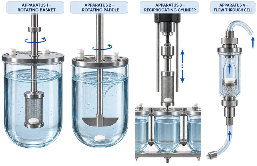
Apparatus 1—Rotating Basket
USP Apparatus 1 uses a cylindrical basket attached to a rotating shaft. The dosage form is placed inside the basket, which rotates in the dissolution medium.
The basket configuration may be appropriate when a dosage form:
- floats
- adheres to the vessel
- disintegrates into material requiring containment
- must be maintained at a controlled position
- is specified for basket testing by an approved analytical procedure
Qualification must address basket dimensions, mesh condition, attachment, deformation, cleanliness, wobble, and rotational behavior.
Apparatus 2—Rotating Paddle
USP Apparatus 2 uses a paddle attached to a rotating shaft. The dosage form is normally placed at the bottom of the vessel beneath the paddle.
The paddle configuration is widely used for tablets, capsules, and suspensions. Qualification must address paddle dimensions, blade condition, shaft alignment, tool height, rotational speed, wobble, and the condition of the vessel bottom.
Sinkers may be used when permitted by the approved method to keep a dosage form submerged. Sinker design and use can alter hydrodynamics and should be controlled by the analytical procedure.
Other Apparatus Types
Other compendial configurations include:
- Apparatus 3—reciprocating cylinder
- Apparatus 4—flow-through cell
- Apparatus 5—paddle over disk
- Apparatus 6—rotating cylinder
- Apparatus 7—reciprocating holder
These systems have different mechanical and operational characteristics. Their qualification may require verification of reciprocation rate, stroke length, cell dimensions, flow rate, flow profile, media switching, holder configuration, disk placement, or other technology-specific functions.
A protocol written for Apparatus 1 and 2 should not be applied automatically to Apparatus 3–7.
The following illustration compares the mechanical arrangements and fluid-motion principles of four principal dissolution apparatus configurations.
Intended Use and User Requirements
The analytical instrument user requirements should define the actual intended use of the dissolution system.
Applicable requirements may include:
- dosage forms and product types
- immediate-release or modified-release testing
- required apparatus types
- number of vessel positions
- required medium volumes
- operating-temperature range
- rotational-speed range
- applicable sampling intervals
- manual or automated dosage introduction
- manual or automated sampling
- simultaneous or sequential sampling
- filtration requirements
- medium replacement
- offline or online analysis
- UV-Vis or HPLC integration
- calculation requirements
- report format
- electronic-record controls
- audit trails
- interfaces
- backup and retention
- throughput
- cleaning
- preventive maintenance
- environmental requirements
Requirements should distinguish equipment capability from product-specific analytical conditions. The system may be capable of a broad speed or temperature range while routine procedures use only a limited portion of that range.
Design Qualification and Supplier Assessment
Design Qualification and supplier assessment should confirm that the proposed configuration supports the approved intended use.
The assessment should consider:
- apparatus configuration
- vessel capacity and geometry
- vessel mounting and retention
- shaft design
- paddle and basket compatibility
- tool-change controls
- drive-head stability
- centering capability
- height adjustment
- speed range and control
- heating technology
- temperature-control range
- temperature uniformity
- vessel-cover design
- evaporation control
- dosage-delivery options
- sampling configuration
- filtration
- tubing materials
- pump type
- medium replacement
- analytical interfaces
- software functions
- electronic-record controls
- cleaning access
- calibration access
- supplier qualification documents
- service support and replacement parts
For automated systems, the design review should evaluate whether the sample path is compatible with the intended compounds, media, surfactants, concentrations, sampling volumes, and analytical finish.
Supplier documentation may support qualification only after its applicability to the purchased configuration and intended use has been assessed.
Installation Qualification
Analytical Instrument Installation Qualification should document the installed configuration and supporting environment.
Applicable IQ checks include:
- manufacturer and model
- serial number
- equipment identification
- number of vessel positions
- installed vessel type
- installed shaft types
- paddle and basket identification
- water bath or vessel-heating configuration
- external circulator
- temperature probes
- sampling system
- pumps
- filters
- tubing
- fraction collector
- medium-replacement system
- dosage-delivery system
- UV-Vis or HPLC interface
- control computer
- software version
- firmware version
- network configuration
- data-storage location
- backup connection
- manuals and certificates
- supplier installation records
The installed baseline should also document:
- apparatus location
- bench or support surface
- leveling
- electrical supply
- water connections where applicable
- drain arrangements
- environmental conditions
- proximity to vibration sources
- airflow or drafts capable of affecting temperature or evaporation
- surrounding equipment
- space for operation, maintenance, and mechanical measurements
Replacement vessels, paddles, baskets, shafts, cannulas, and other product-contact or hydrodynamically significant components should be identified and controlled.
Operational Qualification Strategy
Operational Qualification and functional testing should verify critical mechanical, thermal, sampling, control, alarm, and data functions.
The OQ scope may include:
- vessel condition and dimensional conformity
- vessel position
- apparatus level
- shaft centering
- shaft verticality
- paddle and basket condition
- tool dimensions
- paddle or basket height
- shaft wobble
- basket wobble
- rotational-speed accuracy
- rotational-speed stability
- temperature accuracy
- temperature uniformity
- timer accuracy
- dosage-delivery functions
- sampling position
- sampling timing
- sample-volume accuracy
- replacement-volume accuracy
- pump operation
- filtration
- carryover
- communication
- calculations
- alarms and error handling
- software
- electronic records
- backup and restoration
The following illustration maps the principal dissolution components to their mechanical qualification controls.
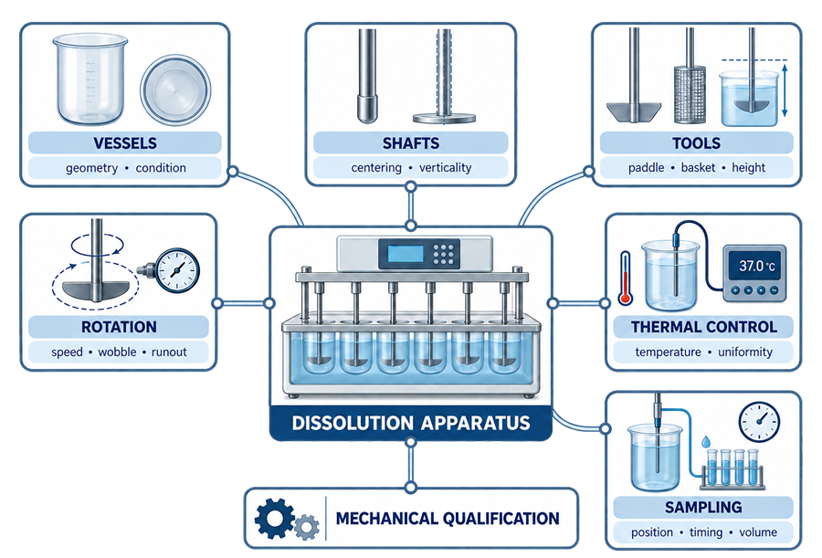
Acceptance criteria should be taken from the applicable compendial chapter, approved procedure, manufacturer specification, internal requirement, or scientifically justified qualification standard. Criteria should not be reconstructed from memory or copied from an obsolete protocol without verification.
Mechanical Qualification
Mechanical qualification confirms that measurable physical and operational characteristics of the apparatus remain within defined requirements.
For Apparatus 1 and 2, the program should address applicable characteristics such as:
- vessel dimensions
- vessel condition
- vessel seating
- apparatus level
- shaft centering
- shaft verticality
- paddle or basket height
- shaft wobble
- basket wobble
- rotational speed
- temperature
- timer operation
- vibration
Mechanical qualification should use calibrated reference devices with suitable range, resolution, and uncertainty.
Results should be recorded by vessel position where position-specific performance is relevant. An average across all positions can conceal an unacceptable individual position.
Apparatus Level
The apparatus should be installed and maintained in a level condition.
Level affects:
- shaft verticality relative to the vessel
- paddle or basket position
- dosage-form location
- vessel hydrodynamics
- repeatability among positions
Level should be checked using a suitable calibrated or verified device at locations defined by the apparatus design or qualification procedure.
Movement of the apparatus, bench adjustment, floor work, major maintenance, or relocation may require the level to be rechecked.
Vessel Condition and Geometry
Vessel geometry directly affects fluid movement around the dosage form. Qualification and routine inspection should address:
- overall dimensions
- internal diameter
- height
- hemispherical bottom
- flange or rim
- wall condition
- bottom condition
- scratches
- chips
- cracks
- deformation
- residue
- etching
- clouding
- manufacturing irregularities
- secure seating
- position identification
A vessel can appear serviceable while having dimensional or surface differences capable of changing hydrodynamics. Conversely, a minor cosmetic mark does not automatically make a vessel unsuitable. The decision should consider location, severity, applicable dimensional requirements, and potential effect on testing.
Vessels should not be interchanged without control when the qualification strategy or historical baseline is position-specific.
Vessel Positioning and Retention
Each vessel should sit reproducibly in the apparatus.
Checks should address:
- correct seating
- stable retention
- repeatable orientation where required
- absence of rocking
- alignment with the shaft
- compatibility with vessel covers
- clearance for sampling cannulas
- correct position identification
Clamps, locating rings, clips, or other retention components should not distort the vessel.
Shaft Centering
Shaft centering verifies the position of the rotational axis relative to the vessel.
An off-center shaft can create position-dependent flow patterns and change the interaction between the medium and dosage form. Centering should therefore be measured relative to the vessel at the specified location or locations using a suitable device.
The assessment should distinguish:
- vessel centering within the apparatus
- shaft centering relative to the vessel
- sampling-cannula position relative to the shaft and vessel
A centered shaft does not by itself demonstrate verticality or acceptable wobble.
Shaft Verticality
Verticality confirms that the shaft is acceptably perpendicular to the horizontal reference plane.
A tilted shaft can cause the paddle or basket to follow an eccentric path even when it appears centered at one elevation. Verticality should be checked using a suitable measurement device and defined procedure.
Apparatus level, shaft verticality, shaft centering, and wobble are related but separate characteristics. One passing measurement should not be used as evidence that the others are acceptable.
Paddle and Basket Dimensions
Paddles and baskets should meet applicable dimensional and material requirements.
Inspection and measurement may address:
- shaft diameter
- overall tool dimensions
- paddle-blade dimensions
- paddle-blade shape
- basket dimensions
- basket mesh
- basket attachment
- basket clips
- welds or joints
- coating condition
- corrosion
- deformation
- cleanliness
- identification
Tools should be protected from bending and damage during cleaning, transport, and storage.
A visibly damaged or distorted paddle or basket should not remain in service solely because the apparatus passes a speed check.
Paddle and Basket Height
Tool height controls the vertical location of the paddle or basket relative to the vessel bottom.
Height should be measured using a suitable gauge or measurement system with the vessel correctly seated. The measurement approach should account for the geometry of the tool and vessel.
Potential causes of incorrect height include:
- improper installation
- loose shaft coupling
- incorrect adjustment
- mismatched shaft
- damaged component
- incorrect vessel seating
- drive-head movement
Height should be rechecked after tool replacement, shaft work, drive-head adjustment, vessel-retention repair, or another change capable of altering vertical position.
Shaft Wobble and Runout
Wobble describes lateral movement of a rotating shaft or attached tool. Runout is commonly evaluated using a dial indicator or another suitable measurement device.
Excessive movement may result from:
- bent shaft
- damaged coupling
- incorrect installation
- worn bearing
- misalignment
- distorted paddle
- damaged basket
- loose attachment
- drive-system wear
Measurement location and method must be defined because the observed value depends on where and how it is measured.
Wobble should not be evaluated only by visual observation when a quantitative requirement applies.
Basket Wobble
Basket wobble may arise from deformation, poor attachment, damaged clips, off-center mounting, shaft misalignment, or basket construction.
The qualification program should define:
- basket installation procedure
- measurement location
- rotational speed during measurement
- reference device
- acceptance criterion
- handling of position-specific failures
A passing shaft-wobble measurement does not necessarily establish acceptable basket behavior.
Rotational-Speed Accuracy and Stability
Rotational speed affects hydrodynamics and drug-release rate.
Qualification should verify:
- displayed versus measured speed
- accuracy at representative operating speeds
- stability during operation
- position consistency where relevant
- response to speed changes
- programmed operation
- alarm or failure response
- recovery after interruption
Speed should be measured with a calibrated tachometer or another suitable reference method. Testing should cover the speeds used by approved procedures rather than only one convenient setpoint.
The apparatus should reach and maintain the required speed before or at the procedurally defined start of the test.
Temperature Accuracy and Uniformity
Dissolution testing commonly requires the medium to be maintained near physiological temperature. The exact requirement must come from the applicable procedure or compendial standard.
Qualification should evaluate:
- displayed temperature
- reference temperature
- temperature at each vessel position
- uniformity among positions
- heating response
- stabilization time
- control during a representative run
- recovery after vessel access or medium addition
- high- and low-temperature alarms
- circulator or heater failure response
Temperature should be measured in the medium or at a location demonstrated to represent the medium. A water-bath display alone does not establish the temperature in each dissolution vessel.
Where individual vessel heaters are used, each heating position should be evaluated.
Water Bath and Individual Vessel Heating
A water-bath system may include:
- heater
- circulation pump
- water-level control
- temperature sensor
- bath cover
- drain
- external circulator
Continued control should address bath cleanliness, microbial growth, corrosion, leaks, circulation, evaporation, water level, and temperature stability.
Individual vessel-heating systems eliminate the shared bath but introduce position-specific heaters, sensors, controllers, and heat-transfer characteristics. Their qualification should establish equivalent control at every intended position.
Timer and Sequence Control
Timing can affect dosage introduction, sampling, medium replacement, and calculated dissolution results.
Applicable checks include:
- elapsed-time accuracy
- programmed sampling times
- sequence start
- staggered dosage introduction
- simultaneous dosage introduction
- alarm timing
- sampling duration
- replacement timing
- event timestamps
- synchronization with connected analytical systems
For staggered introduction, the system should preserve the correct elapsed time for each vessel. It should not assign one common nominal time where actual vessel start times differ.
Vibration Control
External or apparatus-generated vibration can affect dosage-form movement, disintegration, cone formation, and hydrodynamics.
Potential sources include:
- drive motor
- worn bearings
- circulation pump
- water-bath components
- loose panels
- unstable bench
- centrifuges
- shakers
- compressors
- nearby production equipment
- doors or building movement
- repeated contact with the apparatus
Qualification should include an assessment of the installed environment and observation during representative operation.
A universal numerical vibration limit may not be appropriate without a defined measurement method and applicable requirement. The control strategy should emphasize stable installation, absence of abnormal vibration, investigation of changes, and quantitative testing where justified.
Medium Preparation and Control
The apparatus qualification boundary may include medium-preparation equipment when it is dedicated to or integrated with the dissolution system.
Relevant controls include:
- medium identity
- composition
- volume
- pH
- temperature
- mixing
- deaeration
- surfactant preparation
- hold time
- storage
- transfer
- contamination prevention
Medium preparation is primarily a procedural and method-control activity, but equipment failures can affect dissolution results.
Qualification should distinguish apparatus capability from product-specific decisions about medium composition, sink conditions, surfactants, and pH.
Deaeration
Dissolved gases can form bubbles on the dosage form, basket, vessel, or paddle and may alter dissolution behavior.
Where deaeration is required, controls may include:
- deaeration method
- temperature
- vacuum
- mixing
- duration
- transfer
- hold time
- prevention of re-aeration
- verification of effectiveness where appropriate
Possible approaches include vacuum filtration, heating with vacuum, membrane degassing, helium sparging, or another validated procedure.
The apparatus should not be considered qualified merely because a medium-degassing function operates. The effectiveness and suitability of the selected procedure belong to analytical method development or verification.
Medium Volume and Evaporation
Medium volume affects concentration calculations, hydrodynamics, and sink conditions.
Controls should address:
- preparation volume
- delivered volume
- vessel fill level
- volume at test temperature
- sampling losses
- medium replacement
- evaporation
- vessel covers
- test duration
- calculation corrections
Long-duration tests and elevated-temperature operations may require specific evaporation controls. Differences among vessel covers or sampling openings can create position-dependent loss.
Dosage-Unit Introduction
Dosage units may be introduced manually or by an automated delivery mechanism. Qualification or procedural controls should address:
- correct vessel
- correct sequence
- timing
- complete release
- absence of sticking
- synchronization with test start
- detection of failed delivery
- recovery from interruption
- electronic documentation
For manual introduction, analyst technique and timing controls may be significant. For automated introduction, the mechanism and software become part of the qualified system.
Sinkers and Dosage-Form Position
Sinkers may be used to prevent capsules or tablets from floating.
Controls should include:
- approved sinker design
- dimensions
- material
- condition
- cleanliness
- assignment to the method
- consistent use
- effect on hydrodynamics
- replacement criteria
Improvised or inconsistent sinkers should not be used in GMP testing. A change in sinker design can be a method change rather than simple consumable replacement.
Manual Sampling
Manual sampling should follow a defined procedure controlling:
- sampling time
- sampling position
- cannula depth
- radial location
- distance from moving components
- withdrawal volume
- withdrawal rate
- filtration
- sample container
- medium replacement
- calculation correction
- documentation
The analyst should avoid disturbing the dosage form, cone, basket, paddle, or medium flow.
Manual sampling variability may require analyst training and qualification in addition to apparatus qualification.
Automated Sampling Systems
An automated sampling system may include:
- fixed or movable cannulas
- manifold
- valves
- pumps
- tubing
- filters
- sample loops
- fraction collector
- online UV-Vis cells
- medium-replacement system
- control software
Qualification should verify the complete sample path and its coordination with vessel timing.
Applicable tests include:
- cannula position
- insertion and withdrawal
- sampling time
- sampling duration
- withdrawal volume
- volume repeatability
- replacement volume
- pump direction
- tubing assignment
- vessel-to-channel mapping
- filtration
- carryover
- sample recovery
- fraction-collector position
- vial identification
- communication failure
- interrupted sequence
- return-to-safe-state behavior
Automation reduces some operator variability but adds pumps, tubing, software, interfaces, and opportunities for cross-channel or sample-identification errors.
Sampling Position
Sampling location should be controlled because concentration may not be uniform throughout the vessel.
The procedure should define:
- vertical depth
- radial location
- relationship to the vessel wall
- relationship to the shaft
- relationship to the paddle or basket
- cannula orientation
- whether the cannula remains inserted
A fixed sampling assembly should be verified at each vessel position. A movable system should be evaluated for repeatable insertion and withdrawal.
An incorrectly positioned cannula can alter the sample result or disturb the hydrodynamic environment.
Sample-Volume Accuracy and Replacement
Qualification should verify the amount withdrawn when automated sampling volume affects:
- reported concentration
- remaining vessel volume
- subsequent time points
- replacement-medium calculations
- dilution
- final percentage dissolved
Where medium is replaced, the replacement volume and timing should also be verified.
The calculation must account appropriately for cumulative withdrawal and replacement. Qualification of volume delivery does not by itself establish that the calculation is correct.
Filtration
Filters may remove undissolved particles before UV-Vis or HPLC analysis, but they can also retain drug substance or release interfering material.
Equipment qualification should address:
- correct filter installation
- filter integrity where applicable
- housing compatibility
- automated filter handling
- channel assignment
- leakage
- blockage
- pressure or flow effects
Product-specific filter suitability should be established during analytical procedure development or validation. It may include:
- analyte recovery
- extractables
- adsorption
- required discard volume
- comparison with centrifuged or unfiltered samples
- compatibility with the dissolution medium
A mechanically functional filter is not necessarily analytically suitable.
Tubing, Pumps, and Carryover
Automated sample paths can retain analyte, dilute the sample, adsorb compounds, or transfer residue between time points.
Qualification and method controls should consider:
- tubing material
- internal diameter
- tubing length
- pump type
- pump calibration
- dead volume
- rinse volume
- flow direction
- sample recovery
- adsorption
- carryover
- cross-channel contamination
- replacement interval
- cleaning
Carryover testing should use concentrations and compounds representative of intended applications.
Results obtained from an automated system should be compared with an appropriate reference or manual sampling approach when establishing sample-path recovery.
UV-Vis and HPLC Integration
The dissolution apparatus creates and samples the test environment. UV-Vis or HPLC performs the analytical measurement.
Integrated qualification should address:
- vessel-to-sample mapping
- sample identification
- time-point identification
- dilution
- standard association
- analytical method association
- data transfer
- units
- calculation
- retransmission
- duplicate prevention
- failed sample handling
- reconciliation
- interrupted communication
The connected analytical instrument requires its own qualification. For systems using HPLC as the analytical finish, relevant controls are addressed in HPLC and UHPLC Qualification and Lifecycle Control. UV-Visible spectrophotometers should be qualified separately for wavelength accuracy, photometric accuracy, linearity, stray light, resolution, software, and data integrity.
Mechanical Qualification and Performance Verification
Mechanical qualification and performance verification evaluate different aspects of dissolution apparatus suitability.
| Activity | Primary purpose |
|---|---|
| Mechanical qualification | Confirms measurable physical and operational characteristics such as geometry, alignment, speed, temperature, and wobble |
| Performance verification testing | Evaluates integrated apparatus performance using a defined reference standard and procedure |
| Method system suitability | Confirms acceptable performance for the current analytical method and test sequence |
| Analytical procedure validation | Demonstrates that the product-specific dissolution procedure is suitable for its intended purpose |
These activities are related but are not interchangeable.
Mechanical measurements can identify specific physical deficiencies, but they do not challenge every interaction affecting integrated performance. Performance verification can detect combined effects, but a passing result should not be used to disregard an identified mechanical defect.
USP states that the purpose of its Dissolution Performance Verification Test is to provide evidence of instrument and apparatus suitability. Current procedures and acceptance criteria should be obtained from the applicable USP sources rather than copied from historical protocols.
Performance Verification Testing (PVT)
Performance verification testing should use:
- the currently applicable reference standard
- the current official procedure
- qualified analysts
- controlled medium preparation
- controlled deaeration
- calibrated analytical measurement
- defined apparatus configuration
- complete documentation
- current acceptance criteria
The protocol should control:
- reference-standard lot
- storage and handling
- medium
- medium preparation
- medium volume
- temperature
- apparatus type
- paddle or basket speed
- sampling time
- sampling position
- filtration
- analytical finish
- calculation
- acceptance evaluation
An unsuccessful PVT should trigger a documented investigation. Potential causes include:
- mechanical condition
- vessel variability
- shaft alignment
- basket condition
- temperature
- speed
- vibration
- medium preparation
- deaeration
- sampling
- filtration
- analyst technique
- analytical measurement
- calculation
- reference-standard handling
The investigation should not assume that the apparatus is the only possible source of failure.
Performance Qualification and Intended-Use Verification
Analytical Instrument Performance Qualification and Continued Verification should demonstrate that the qualified apparatus supports representative intended-use procedures.
PQ evidence may include:
- representative product or surrogate
- approved apparatus configuration
- representative speed
- representative medium volume
- representative temperature
- manual or automated dosage introduction
- sampling at applicable time points
- filtration
- sample recovery
- UV-Vis or HPLC integration
- calculations
- reports
- system suitability
- data review
- interface transfer
PQ should not duplicate product-specific method validation when applicable method evidence already demonstrates performance on the identified qualified system.
Analytical Procedure Validation Boundary
Dissolution apparatus qualification does not establish that a dissolution procedure is discriminatory or suitable for a specific product.
Method development and validation may address:
- apparatus selection
- agitation rate
- medium composition
- medium volume
- pH
- buffer capacity
- surfactant
- sink conditions
- deaeration
- dosage-form behavior
- sinker selection
- sampling intervals
- sampling position
- filtration
- sample stability
- analytical finish
- specificity
- accuracy
- precision
- linearity
- range
- robustness
- discriminatory capability
- acceptance criteria
FDA’s Dissolution Testing of Immediate Release Solid Oral Dosage Forms describes dissolution testing as a tool for formulation development, batch quality assessment, and continued product quality after certain changes.
The qualification article should remain focused on apparatus capability and lifecycle control rather than becoming a product-specific dissolution-method article.
Software and Data Integrity
Dissolution software may control:
- apparatus configuration
- temperature
- speed
- timers
- dosage introduction
- sampling schedules
- pumps
- medium replacement
- UV-Vis acquisition
- analytical interfaces
- calculations
- result evaluation
- reports
- audit trails
- electronic signatures
- data retention
Qualification should be coordinated with analytical instrument software validation.
Site-specific testing should address applicable functions such as:
- method creation
- method approval
- version control
- apparatus selection
- vessel-position assignment
- sample identification
- product and batch identification
- sequence creation
- dosage-introduction timing
- sampling schedule
- sampling-volume configuration
- replacement-volume configuration
- dilution factors
- standard calculations
- percentage-dissolved calculations
- cumulative-volume corrections
- acceptance-stage calculations
- result rounding
- reintegration or reprocessing where applicable
- review and approval
- report generation
- user roles
- audit trails
- electronic signatures
- backup and restoration
- interfaces
Dynamic electronic records may include:
- instrument method
- dissolution conditions
- sample sequence
- vessel assignment
- actual speed
- actual temperature
- event times
- sampling events
- raw absorbance or chromatographic data
- calibration data
- calculations
- results
- audit trails
- review records
- metadata
These records should remain linked and available for reconstruction of the test.
Applicable regulatory controls include 21 CFR 211.68 and 21 CFR 211.194. The FDA Data Integrity and Compliance With Drug CGMP guidance should be considered when establishing access, audit-trail, review, backup, and retention controls.
Calculation Verification
Calculation testing should address applicable formulas such as:
- concentration from absorbance or chromatographic response
- dilution factors
- standard potency
- standard preparation
- sample volume
- dosage strength
- percentage of label claim dissolved
- cumulative sample withdrawal
- replacement-medium correction
- volume change
- result rounding
- staged acceptance evaluation
Calculations should be challenged with known inputs and independently verified expected outputs.
A correct concentration result does not demonstrate that vessel assignment, time point, dosage strength, withdrawal correction, or acceptance-stage logic is correct.
Audit Trails and Access Control
Audit-trail testing should address changes to GMP-relevant information such as:
- instrument methods
- sampling times
- rotational speed
- temperature
- vessel assignment
- sample identification
- calculation parameters
- results
- report templates
- user roles
- system configuration
User access should reflect assigned responsibilities. Analysts should not have uncontrolled administrator privileges or the ability to overwrite original records.
Additional controls are discussed in:
- Audit Trails and Data Change Control
- Access Control and Electronic Signatures
- Electronic Record Lifecycle and Retention
Routine Operational Checks
Routine checks should be capable of detecting conditions that may develop between formal qualification events.
Checks may include:
- apparatus level
- vessel cleanliness and condition
- vessel seating
- shaft condition
- paddle condition
- basket condition
- tool attachment
- tool height
- speed
- temperature
- bath level
- abnormal vibration
- unusual noise
- sampling-cannula position
- tubing and filter condition
- leaks
- system readiness
- date and time
- available data storage
The program should define:
- check frequency
- responsible role
- method
- acceptance criterion
- documentation
- failure response
- escalation requirements
Not every mechanical characteristic must necessarily be measured before every run. The control strategy should combine pre-use inspection, scheduled measurement, calibration, PVT, system suitability, maintenance, and trend review.
System Suitability and Continued Performance
Product-specific system suitability may evaluate:
- standard response
- standard precision
- vessel-to-vessel precision
- dissolution result variability
- reference-product behavior
- blank response
- filter performance
- analytical finish
- calculation
- other method-defined criteria
System suitability evaluates the current analytical sequence. It does not replace apparatus qualification, calibration, or method validation.
Aggregated results can support continued performance review by identifying:
- increasing vessel-to-vessel variability
- recurring position-specific differences
- declining sample recovery
- increasing carryover
- timing problems
- temperature instability
- repeated mechanical adjustment
- repeated PVT difficulty
- increasing invalid or aborted runs
Qualification and Verification Intervals
No single qualification interval is appropriate for every dissolution system. Intervals should consider:
- intended use
- frequency of operation
- product criticality
- apparatus configuration
- manual or automated sampling
- number of interchangeable components
- historical mechanical stability
- PVT history
- calibration results
- maintenance history
- failure history
- relocation frequency
- environmental vibration
- supplier recommendations
- applicable compendial requirements
- internal procedures
The program should identify which controls are:
- checked before use
- checked for each run
- measured periodically
- verified through PVT
- reviewed through system suitability
- triggered by maintenance
- triggered by change or failure
Calendar-based activities and event-driven verification should operate together.
Preventive Maintenance
Preventive maintenance may include:
- drive belts
- motor
- bearings
- shaft couplings
- height-adjustment mechanisms
- vessel-retention devices
- water-bath circulator
- heater
- bath sensor
- individual vessel heaters
- pumps
- valves
- tubing
- sampling cannulas
- filters
- dosage-delivery mechanisms
- fraction collector
- workstation
- data-storage components
Maintenance frequency should reflect equipment use, supplier recommendations, observed wear, medium exposure, failure history, and performance trends.
Maintenance should not include uncontrolled adjustment of qualified characteristics. Post-maintenance verification must be selected according to the functions affected.
Component Replacement
Replacement of a vessel, shaft, paddle, basket, sampling cannula, pump tube, or other component should follow a defined process.
The process should address:
- approved replacement part
- material and dimensions
- component identification
- incoming inspection
- installation
- position assignment
- cleaning
- impact assessment
- required mechanical checks
- required functional testing
- baseline update
- release to use
Examples:
| Replacement | Typical verification considerations |
|---|---|
| Vessel | Dimensions, condition, seating, centering, tool height, applicable performance evidence |
| Shaft | Verticality, centering, height, wobble, speed |
| Paddle | Dimensions, condition, height, wobble |
| Basket | Dimensions, mesh, attachment, wobble |
| Temperature probe | Calibration, position-specific temperature verification |
| Sampling cannula | Position, depth, volume, channel assignment |
| Pump or tubing | Volume accuracy, recovery, carryover, leakage |
| Control computer | Software configuration, communication, data integrity, regression testing |
The exact scope should be justified by impact rather than selected automatically from a fixed list.
Common Failure Modes
Vessel and alignment failures
- scratched or damaged vessel
- dimensional nonconformity
- incorrect vessel seating
- unstable vessel
- off-center shaft
- nonvertical shaft
- incorrect tool height
- bent shaft
- excessive wobble
Paddle and basket failures
- bent paddle
- damaged blade
- corroded surface
- distorted basket
- damaged mesh
- loose basket
- incorrect attachment
- contamination
- use of the wrong tool
Drive and speed failures
- speed bias
- unstable speed
- worn belt
- bearing wear
- coupling failure
- position-dependent rotation
- abnormal vibration
- motor failure
Temperature failures
- bath-temperature bias
- inadequate circulation
- position nonuniformity
- failed heater
- failed temperature sensor
- inadequate stabilization
- low bath level
- excessive evaporation
Sampling failures
- incorrect cannula position
- incorrect sampling time
- wrong vessel-to-channel mapping
- inaccurate withdrawal volume
- incorrect replacement volume
- blocked tubing
- leaking connection
- pump failure
- filter adsorption
- sample carryover
- fraction-collector misalignment
Software and data failures
- incorrect method version
- unauthorized parameter change
- incorrect vessel assignment
- incorrect time-point association
- calculation error
- cumulative-volume correction error
- communication failure
- incomplete record
- audit-trail deficiency
- unavailable storage
- failed backup
- uncontrolled report template
Recurring failures should be evaluated collectively rather than closed only as isolated maintenance events.
Change and Requalification
Potential requalification triggers include:
- relocation
- bench replacement
- leveling adjustment
- drive-head repair
- motor or bearing replacement
- shaft replacement
- paddle or basket replacement
- vessel replacement
- vessel-retention modification
- speed-controller replacement
- temperature-sensor replacement
- heater or circulator repair
- sampling-system modification
- pump replacement
- tubing-material change
- cannula replacement or repositioning
- filtration-system change
- medium-replacement change
- dosage-delivery modification
- UV-Vis or HPLC interface change
- workstation or server replacement
- software or firmware upgrade
- calculation change
- repeated PVT failure
- recurring mechanical failure
- adverse performance trend
- expansion to a more demanding intended use
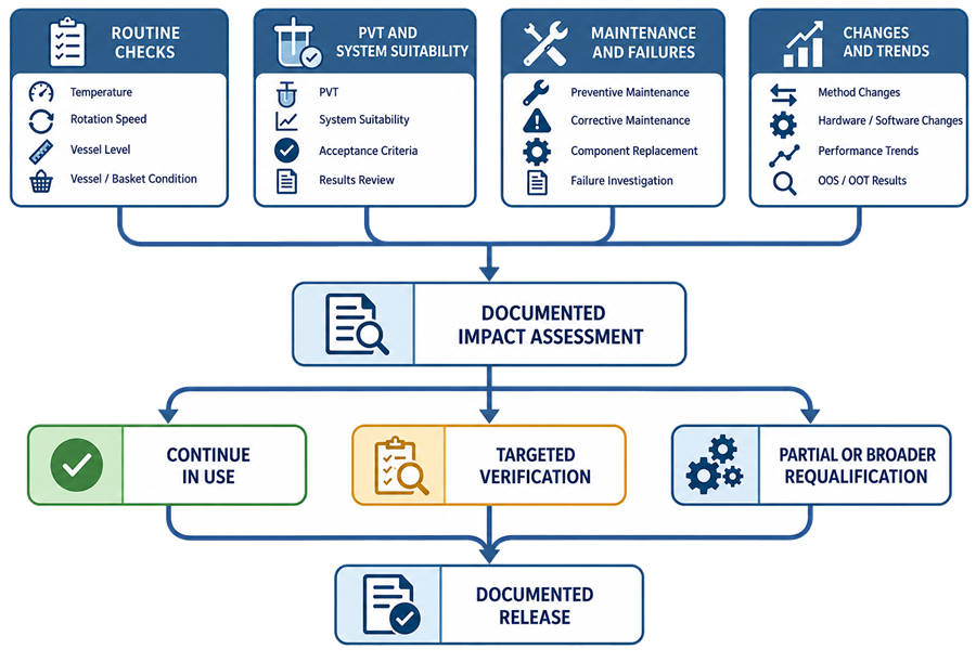
The impact assessment should determine whether the appropriate response is:
- routine operational check
- component inspection
- calibration
- targeted mechanical measurement
- temperature verification
- sampling-volume verification
- sample-recovery study
- carryover testing
- software regression testing
- interface testing
- PVT
- targeted PQ
- partial requalification
- broader requalification
The analytical instrument requalification framework should determine scope. Full repetition of the original qualification is not automatically required after every maintenance activity.
The following illustration shows how routine evidence, maintenance, failures, and changes should be translated into continued-use or requalification decisions.
Return to Service
Return-to-service evidence may include:
- completed maintenance record
- correct component installation
- visual inspection
- apparatus level
- shaft centering
- shaft verticality
- tool height
- wobble
- rotational speed
- temperature
- sampling position
- sampling volume
- replacement volume
- sample recovery
- carryover
- communication check
- software regression testing
- PVT
- system suitability
- approved release
A supplier service report confirms that work was performed. It does not by itself demonstrate that all affected GMP functions remain acceptable.
Periodic Review
Periodic review should consolidate evidence from:
- qualification
- calibration
- PVT
- system suitability
- routine checks
- maintenance
- component replacement
- deviations
- invalidated tests
- out-of-specification investigations
- adverse trends
- software changes
- audit-trail review
- user-access review
- backup and restoration
- supplier support
- obsolescence
The review should determine whether:
- the intended use remains unchanged
- the installed configuration matches the approved baseline
- mechanical performance remains acceptable
- specific vessel positions show adverse behavior
- maintenance frequency remains appropriate
- recurring adjustments indicate deterioration
- sampling performance remains controlled
- software and data controls remain effective
- qualification intervals remain justified
- additional verification or replacement is required
Common Qualification Deficiencies
Common deficiencies include:
- treating dissolution as only a temperature-and-speed test
- failing to control vessel geometry and condition
- averaging results across positions and concealing an unacceptable vessel
- checking centering without checking verticality
- checking verticality without checking wobble
- visually assessing wobble when quantitative criteria apply
- failing to measure paddle or basket height
- using damaged or unidentified baskets
- interchanging vessels without control
- relying only on the water-bath display for temperature
- ignoring environmental or apparatus-generated vibration
- qualifying the base apparatus but excluding automated sampling
- failing to verify cannula position
- omitting sample-withdrawal and replacement-volume accuracy
- failing to evaluate filtration recovery
- ignoring tubing adsorption and carryover
- failing to verify vessel-to-channel mapping
- treating PVT as a substitute for mechanical qualification
- treating mechanical qualification as proof of method suitability
- using obsolete PVT instructions or acceptance criteria
- failing to investigate recurring position-specific results
- accepting a service report without post-maintenance verification
- failing to assess vessel, shaft, paddle, or basket replacement
- omitting calculations, audit trails, or electronic records from qualification
Conclusion
Dissolution apparatus qualification must establish control of the physical environment in which drug release is measured. Vessel geometry, shaft alignment, paddle or basket position, rotational behavior, temperature, vibration, dosage introduction, and sampling can all influence the observed dissolution result.
Mechanical qualification provides direct evidence that measurable apparatus characteristics remain acceptable. Performance verification provides complementary evidence of integrated apparatus suitability. Product-specific system suitability and analytical procedure validation provide different forms of evidence and should not be treated as replacements for instrument qualification.
Continued fitness for use depends on routine inspection, calibration, mechanical measurements, performance verification, system suitability, preventive maintenance, component control, data review, change assessment, and proportionate requalification throughout the apparatus lifecycle.