

Gas Chromatography and Headspace System Qualification
Gas chromatography (GC) separates, identifies, and quantifies volatile or semivolatile compounds. In pharmaceutical laboratories, GC is commonly used for residual solvents, volatile impurities, alcohols, residual monomers, degradation products, packaging-related compounds, and extractables and leachables.
A headspace sampler introduces volatile compounds from the gas phase above a sealed liquid or solid sample. It is commonly integrated with GC for residual-solvent testing because it limits transfer of nonvolatile sample matrix into the chromatographic inlet and column.
Qualification should demonstrate that the complete GC or GC–headspace system is suitable for its intended analytical use. The qualified boundary may include gas supplies, pressure and flow controls, inlet, autosampler, headspace sampler, column oven, detector, instrument controller, acquisition workstation, chromatography software, electronic-record storage, and applicable interfaces.
Purpose and Qualification Objectives
GC and headspace qualification should demonstrate, as applicable, that:
- the installed configuration matches the approved system design
- carrier-gas and detector-gas supplies are suitable
- pressure and flow controls operate accurately and consistently
- the gas path is acceptably leak-tight
- inlet temperature and operating functions are controlled
- liquid autosampler injections are sufficiently precise
- the GC oven maintains temperature and executes programmed ramps correctly
- the headspace sampler controls incubation, agitation, pressurization, sampling, and transfer
- sample-loop and transfer-line temperatures remain suitable
- detector response, stability, sensitivity, and gases are controlled
- data are acquired without loss, distortion, or incorrect sample association
- chromatography software performs approved processing, calculation, review, and reporting functions
- electronic records and metadata remain complete and protected
- representative methods meet defined performance and system-suitability criteria
- routine checks, maintenance, and performance review maintain continued fitness for use
- changes, repairs, and failures receive a documented requalification assessment
Qualification depth should follow the approved risk-based analytical instrument qualification strategy and the system’s analytical instrument risk classification.
GC and Headspace System Architecture
A typical GC system includes:
- carrier-gas source
- regulators and gas lines
- gas purifiers or traps
- electronic pressure or pneumatic control
- inlet
- liquid autosampler or manual injection port
- capillary or packed column
- programmable column oven
- detector
- detector-gas controls
- instrument controller
- acquisition workstation
- chromatography data system
- database or electronic-record repository
- network and interfaces
- backup and archival services
A static headspace sampler may include:
- vial tray
- robotic vial transport
- incubation oven
- agitation mechanism
- vial-pressurization system
- heated sampling needle
- sample loop or gas-tight syringe
- heated valve
- heated transfer line
- carrier or pressurization gas
- GC synchronization
- headspace control software
The following illustration shows the main GC gas and sample path and the integration of the static headspace sampler with the GC inlet.
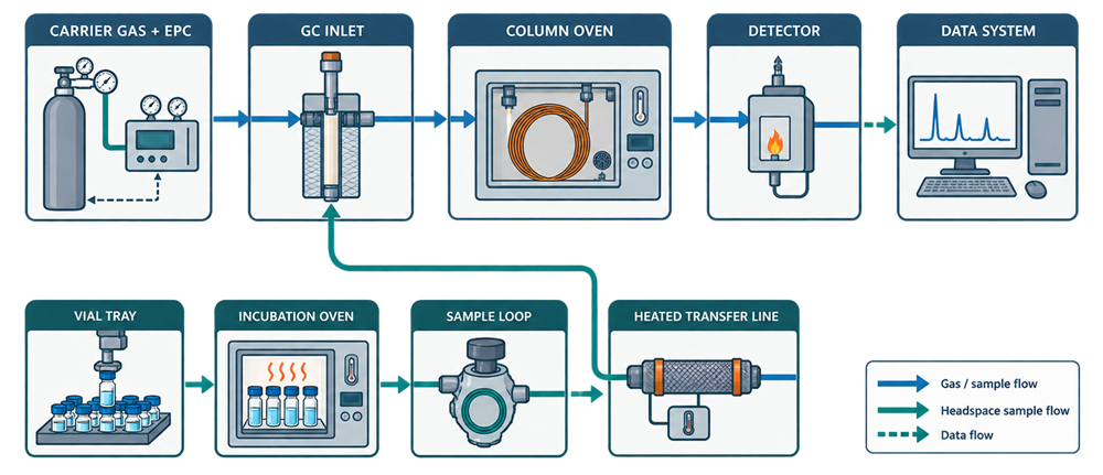
The headspace sampler performs sample preparation and introduction. The GC performs separation and detection. Qualification should verify both subsystems and their coordinated operation.
Static and Dynamic Headspace
Static headspace is the most common pharmaceutical headspace technique. A sealed vial is incubated under controlled conditions until the volatile compounds reach a reproducible distribution between the sample matrix and the gas phase. A portion of the gas phase is then transferred to the GC.
Static headspace qualification commonly addresses:
- incubation temperature
- incubation time
- agitation
- vial pressurization
- sampling
- loop or syringe volume
- valve temperature
- transfer-line temperature
- injection timing
- carryover
- precision
Dynamic headspace, purge-and-trap, and thermal-desorption systems use different collection and transfer principles. They may require qualification of purge flow, trap temperature, desorption, focusing, drying, breakthrough, and recovery. These systems should not automatically be covered by a static-headspace protocol.
This article focuses primarily on conventional GC and static headspace systems.
Intended Use and User Requirements
The analytical instrument user requirements should define how the GC or GC–headspace system will be used.
Applicable requirements include:
- intended tests and sample types
- target compounds
- expected concentration range
- required sensitivity
- required selectivity
- carrier gas
- inlet type
- injection mode
- column type
- oven-temperature range
- temperature-programming requirements
- detector type
- detector gases
- headspace requirement
- headspace-vial type and size
- incubation range
- agitation
- pressurization
- sample-loop or syringe configuration
- sequence capacity
- throughput
- data-acquisition rate
- processing functions
- calculations
- report requirements
- electronic-record controls
- interfaces
- backup and retention
- maintenance and service needs
Requirements should describe the actual analytical applications rather than reproduce the full manufacturer specification.
A system used for routine residual-solvent testing by headspace GC–FID has different qualification needs from a GC–MS system used for identification of unknown volatile compounds.
Design Qualification and Supplier Assessment
Design Qualification and supplier assessment should confirm that the proposed GC and headspace configuration can meet the approved intended use.
The review should address:
- carrier-gas compatibility
- pressure and flow range
- availability of gas purifiers
- inlet design
- split, splitless, on-column, programmed-temperature, or other required injection modes
- autosampler capacity
- syringe range
- oven-temperature range
- oven ramp capability
- cooling and cycle time
- column compatibility
- detector type
- detector gases
- sensitivity
- data-acquisition rate
- headspace incubation capacity
- agitation
- vial-pressurization technology
- loop or syringe sampling
- heated transfer path
- software functions
- electronic-record controls
- infrastructure compatibility
- supplier qualification documents
- service and spare-parts support
For headspace systems, the design review should specifically evaluate whether the incubation, sampling, and transfer design supports the volatility, concentration, matrix, and throughput requirements of the intended procedures.
Supplier documentation may support qualification after its technical adequacy and applicability to the purchased configuration have been assessed.
Installation Qualification
Analytical Instrument Installation Qualification should establish the installed configuration and supporting environment.
Applicable IQ checks include:
- manufacturer and model
- serial numbers
- equipment identification
- installed inlet
- autosampler
- headspace sampler
- sample-loop or syringe configuration
- heated transfer line
- column oven
- detector
- gas-control modules
- computer and workstation
- software version
- firmware versions
- drivers and communication modules
- licenses and enabled features
- network configuration
- data-storage location
- interfaces
- manuals and certificates
- supplier installation records
Gas installation should address:
- gas identity
- required purity
- cylinder, bulk, or generator source
- regulator compatibility
- line materials
- line identification
- operating pressure
- gas filters and purifiers
- moisture, oxygen, or hydrocarbon traps
- detector-gas supplies
- ventilation and exhaust
- leak-check arrangements
- applicable safety controls
The system flow path, headspace connection, software configuration, user roles, data location, system time, and backup connection should be documented as part of the installed baseline.
Operational Qualification Strategy
Operational Qualification and functional testing should challenge the critical functions of the installed GC and headspace configuration. The OQ scope may include:
- gas pressure and flow
- electronic pneumatic control
- leak integrity
- inlet temperature
- liquid injection
- autosampler precision
- oven temperature
- oven programming
- headspace incubation
- vial agitation
- vial pressurization
- sample-loop temperature
- transfer-line temperature
- headspace sampling and transfer
- detector response
- detector stability
- alarms and error handling
- module communication
- data acquisition
- chromatography software
- electronic records
- interfaces
- backup and restoration
The following illustration maps the primary GC and headspace modules to their principal qualification controls.
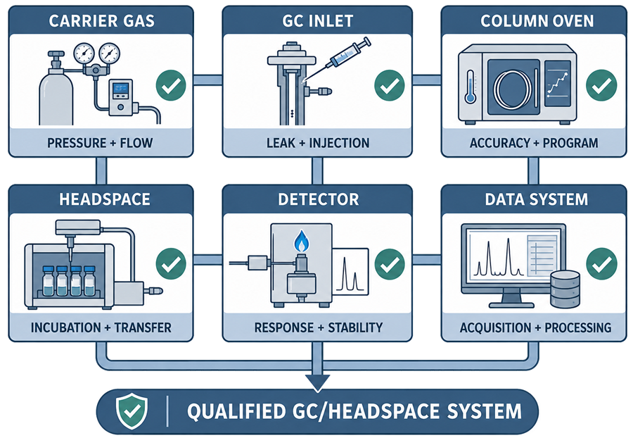
Acceptance criteria should be based on intended use, approved analytical procedures, manufacturer specifications, development knowledge, compendial requirements where applicable, and scientific justification.
Carrier-Gas Quality and Control
Carrier gas transports the sample through the inlet and column. Gas identity, purity, pressure, flow, and cleanliness can affect retention, resolution, detector response, baseline stability, column life, and system reliability.
Qualification and operational controls should consider:
- gas identity
- gas purity
- supply pressure
- regulator condition
- gas-line compatibility
- moisture removal
- oxygen removal
- hydrocarbon removal
- trap condition
- electronic pressure-control configuration
- column flow
- linear velocity
- split flow
- septum purge flow
- detector makeup gas
- response to low supply pressure
- response to depleted gas
- communication of gas-control status
Gas specifications should support the detector and column technology. The suitability of helium, hydrogen, nitrogen, or another carrier gas depends on the analytical procedure and system design.
A gas generator should be treated as supporting equipment with defined maintenance, alarms, purity controls, and service requirements.
Pressure and Flow Qualification
Pressure and flow control influence retention time, efficiency, resolution, response, and method transfer. Applicable tests may address:
- inlet pressure accuracy
- column-flow accuracy
- flow repeatability
- split flow
- septum purge flow
- detector gases
- makeup-gas flow
- pressure programming
- flow programming
- constant-pressure mode
- constant-flow mode
- response to supply-pressure change
- low-pressure alarm
- shutdown or safe response
Testing should cover the range and operating modes used by intended procedures.
Flow may be verified using a calibrated flow-measurement device appropriate for the gas and expected range. The verification should account for measurement conditions where necessary, including temperature, pressure, and gas type.
Electronic pressure-control values should not be accepted solely because they appear on the instrument display. Critical values should be verified through a suitable independent approach or supported by applicable supplier calibration evidence.
Leak Testing
Leaks can change carrier-gas flow, introduce oxygen or moisture, damage columns, create unstable baselines, reduce detector response, and generate unreliable results.
Leak evaluation should address applicable connections such as:
- gas-source connection
- regulator
- purifier and trap connections
- inlet fittings
- septum
- liner seals
- column inlet connection
- column detector connection
- detector gas connections
- headspace gas connections
- vial-pressurization path
- sample loop and valve
- transfer-line connection
Leak testing may use:
- instrument diagnostic functions
- approved electronic leak detector
- pressure-decay test
- flow comparison
- another suitable method
Flammable gas systems require appropriate safety practices. Unapproved leak-detection liquids should not be applied to heated, contaminated, or sensitive analytical connections.
A pressure reading that remains within range does not by itself demonstrate that every relevant connection is leak-tight.
GC Inlet Qualification
The inlet vaporizes and transfers the sample to the chromatographic column. Depending on the configuration, qualification may address:
- inlet temperature accuracy
- temperature stability
- heating response
- split ratio
- split flow
- septum purge flow
- inlet pressure
- purge timing
- injection mode
- inlet liner
- septum condition
- leak integrity
- response to overtemperature
- communication with the data system
Inlet types may include:
- split/splitless
- direct
- on-column
- programmed-temperature vaporizing
- multimode
- gas-sampling valve
Qualification should reflect the installed inlet and intended operating modes. Tests designed for a split/splitless inlet should not be applied automatically to an on-column or valve-injection configuration.
Liquid Autosampler Qualification
A liquid autosampler affects injection precision, sample identity, carryover, sequence execution, and throughput. Applicable tests may include:
- vial position
- tray recognition
- sequence execution
- syringe identification
- syringe-volume configuration
- injection precision
- injection range
- wash cycles
- sample carryover
- solvent selection
- pre- and post-injection washes
- plunger movement
- missing-vial response
- insufficient-sample response
- communication with the GC
- recovery after interruption
Injection precision is commonly assessed through repeated injections of a homogeneous standard and evaluation of peak-area or peak-height variation.
This test principally evaluates autosampler and measurement repeatability. It does not demonstrate independent sample-preparation precision.
Carryover should be challenged using concentrations and compounds representative of the intended analytical procedures.
Manual Injection
Where manual injection is part of the approved use, the qualification strategy should separate instrument capability from analyst technique. Manual injection performance may be influenced by:
- syringe condition
- injection volume
- injection speed
- needle insertion
- timing
- inlet mode
- analyst technique
- sample viscosity
- volatilization
Instrument qualification should verify the inlet and detector functions. Analyst qualification, procedural controls, and method-performance studies may be needed to control manual-injection variability.
Column-Oven Temperature Accuracy
Oven temperature affects retention time, selectivity, resolution, column efficiency, and analysis time. Qualification may address:
- temperature accuracy
- temperature stability
- operating range
- displayed versus measured temperature
- spatial distribution
- heating response
- cooling response
- overtemperature protection
- door-open response
- communication with the data system
Temperature should be measured using a calibrated reference device positioned to represent the controlled column environment.
The number and placement of reference sensors should reflect oven size, configuration, intended temperature range, and risk. Full chamber mapping is not universally necessary for every GC oven, but a single unrepresentative measurement may be insufficient for a large or unusual configuration.
Oven Temperature Programming
Programmed temperature controls are fundamental to many GC procedures. Testing may address:
- initial temperature
- initial hold time
- ramp rate
- intermediate temperature
- intermediate hold
- final temperature
- final hold
- multiple-ramp programs
- maximum programmed rate
- cooling and readiness for the next run
- repeatability
- recorded versus programmed values
The test should represent the rates and temperatures required by intended methods. Testing only a static oven setpoint does not demonstrate the ability to execute a programmed GC method.
Acceptance criteria should consider both temperature accuracy and the ability to follow the programmed profile.
Headspace Sample Preparation
Static headspace analysis depends on reproducible partitioning of volatile compounds between the sample and the gas phase. The amount transferred to the GC may be affected by:
- sample mass or volume
- vial volume
- headspace volume
- diluent
- matrix
- temperature
- incubation time
- agitation
- pressure
- sample-loop volume
- transfer conditions
- vial closure integrity
Qualification should focus on equipment functions, while analytical procedure development and validation establish appropriate sample preparation and equilibration conditions.
The headspace sampler should not be qualified using arbitrary conditions unrelated to the intended methods.
Headspace Incubation Temperature
Incubation temperature strongly affects analyte vapor pressure and partitioning. Qualification may address:
- temperature accuracy
- temperature stability
- operating range
- displayed versus measured temperature
- spatial variation among vial positions
- heating recovery
- programmed setpoint
- overtemperature response
Reference sensors or suitable temperature-measurement methods should represent the vial incubation environment.
The required number of locations should reflect oven design, vial capacity, intended loading pattern, method sensitivity, and risk. A multi-position headspace oven may require more than one measurement location to establish representative control.
Incubation Time and Sequence Timing
Incubation time affects equilibration and analyte response. Qualification should verify applicable timing functions such as:
- incubation duration
- agitation duration
- pressurization time
- loop-fill time
- loop-equilibration time
- injection time
- transfer time
- cycle time
- overlap of vial preparation and GC analysis
- synchronization with GC readiness
Timing may be verified through system records, controlled observation, or another suitable method.
The system should prevent or identify transfer when the GC is not ready. Sequence timing should not permit silent loss, duplication, or misassociation of a headspace injection.
Headspace Agitation
Agitation can accelerate equilibration and improve repeatability. Testing may address:
- agitation enabled or disabled
- agitation speed
- agitation pattern
- programmed duration
- vial handling
- response to mechanical obstruction
- communication of agitation status
Not every method requires agitation. Qualification should verify the functions used by intended methods rather than imposing agitation universally.
Vial Pressurization and Leak Integrity
Many headspace systems pressurize the vial before sampling.
Applicable controls include:
- pressurization-gas identity
- gas pressure
- pressurization time
- pressure release
- sampling-needle operation
- vial sealing
- vial-cap integrity
- detection of missing or leaking vials
- safe handling of pressurized vials
Poor vial sealing can produce low or variable response. Qualification and method procedures should define compatible vial, septum, cap, crimping, or closure arrangements.
Vial closure performance is affected by user technique and consumable selection as well as instrument operation.
Sample-Loop and Transfer-Line Temperature
The sample loop, valve, needle, and transfer line should remain hot enough to avoid condensation or adsorption of target compounds.
Qualification may address:
- sample-loop temperature accuracy
- valve temperature
- needle temperature
- transfer-line temperature
- temperature stability
- displayed versus measured temperature
- overtemperature alarm
- undertemperature alarm
- readiness interlock
Setpoints should support the volatility of target compounds and remain compatible with materials and system limits.
A qualified incubation oven does not demonstrate that the downstream sampling and transfer path is adequately heated.
Headspace Injection Precision
Headspace precision evaluates the reproducibility of incubation, pressurization, sampling, transfer, GC injection, separation, and detection.
The test may use multiple identically prepared vials containing a suitable volatile standard.
The test design should distinguish:
- repeated sampling from one vial, if the system permits it
- injections from independently prepared vials
- vial-to-vial precision
- sequence-position effects
- incubation-position effects
- instrument repeatability
- preparation variability
Independently prepared vials generally provide a more representative challenge of routine headspace operation but include sample-preparation variability.
Acceptance criteria should be based on method requirements and intended use rather than a universal precision limit.
Headspace Carryover
Carryover may occur in:
- sampling needle
- sample loop
- valve
- transfer line
- GC inlet
- column
- detector
A carryover challenge may include:
- analysis of a high-concentration volatile standard
- analysis of a blank vial
- evaluation of target-compound response in the blank
- additional blanks where needed to characterize persistence
The challenge concentration should reflect the highest relevant method concentration and the sensitivity of subsequent tests.
Failure should trigger evaluation of sampling conditions, loop and transfer temperatures, purge functions, contamination, inlet components, column retention, and sequence design.
Detector Qualification
Detector qualification should be specific to the installed detector technology and intended use.
Common GC detectors include:
- flame ionization detector
- thermal conductivity detector
- electron capture detector
- nitrogen-phosphorus detector
- flame photometric detector
- mass-selective detector
Testing appropriate for one detector should not be applied automatically to another.
Flame Ionization Detector
FID qualification may address:
- hydrogen flow
- air flow
- makeup-gas flow
- ignition
- flame status
- detector temperature
- response
- response linearity
- repeatability
- baseline noise
- drift
- flame-out response
- gas-safety controls
Thermal Conductivity Detector
TCD qualification may address:
- reference and column flow
- detector temperature
- filament operation
- response
- stability
- noise
- drift
- gas compatibility
Electron Capture Detector
ECD qualification may address:
- detector temperature
- makeup gas
- response
- sensitivity
- baseline stability
- noise
- applicable source and safety controls
Nitrogen-Phosphorus and Flame Photometric Detectors
Testing may address detector gases, ignition, temperature, element-specific response, sensitivity, noise, drift, and stability.
Mass-Selective Detection
GC–MS qualification may include:
- vacuum
- leak check
- mass-axis calibration
- tuning
- resolution
- sensitivity
- abundance criteria
- mass assignment
- scan and selected-ion modes
- data acquisition
- library or identification functions where used
A GC–MS system requires additional detector-specific scope beyond the basic GC tests described in this article.
Detector Response, Noise, and Drift
Detector response testing may evaluate:
- sensitivity
- repeatability
- response linearity
- reference-compound response
- detector-gas influence
- baseline stability
- signal-to-noise ratio
- noise
- drift
Test conditions should define:
- reference material
- concentration
- injection mode
- column or restriction
- gas conditions
- oven condition
- detector temperature
- data-acquisition rate
- filtering
- measurement interval
- calculation method
Noise represents short-term signal variation. Drift represents progressive baseline movement. They should be evaluated separately when both affect intended method performance.
Data Acquisition
The acquisition path should preserve the detector signal as complete, accurate, and attributable electronic data. Testing may address:
- instrument connection
- detector-channel assignment
- acquisition start and stop
- sampling rate
- sequence association
- sample identification
- method association
- raw-data creation
- metadata
- time synchronization
- interrupted acquisition
- communication failure
- unavailable storage
- record retrieval
- recovery behavior
Narrow GC peaks require an acquisition rate adequate to preserve peak shape, area, and height. The required rate should reflect intended methods and detector response settings.
The system should not silently lose data or associate a chromatogram with an incorrect vial, sample, or sequence entry.
Chromatography Software and Data Integrity
GC software may control:
- instrument configuration
- gas and temperature methods
- headspace methods
- sequences
- acquisition
- integration
- calculations
- reprocessing
- system suitability
- review
- reporting
- audit trails
- electronic signatures
- data retention
Qualification should be coordinated with analytical instrument software validation.
Site-specific testing should address applicable functions such as:
- method creation and approval
- method version control
- sequence creation
- sample and vial identification
- GC–headspace synchronization
- acquisition
- integration
- reintegration
- calculations
- residual-solvent reporting
- system-suitability calculations
- review and approval
- report templates
- user roles
- audit trails
- electronic signatures
- backup and restoration
- interfaces
Dynamic electronic records may include:
- original chromatographic signal
- acquisition method
- headspace method
- sequence
- sample and vial information
- integration events
- processing method
- calculations
- results
- audit trails
- review and approval records
- metadata
These records should remain linked and available for reconstruction of the analytical activity.
The FDA Data Integrity and Compliance With Drug CGMP guidance should be considered when defining access, processing, audit-trail, review, backup, and retention controls.
Additional internal guidance is provided in:
- Audit Trails and Data Change Control
- Access Control and Electronic Signatures
- Electronic Record Lifecycle and Retention
Applicable regulatory requirements include 21 CFR 211.68 and 21 CFR 211.194.
Interface Qualification
GC systems may transfer results to LIMS, stability systems, reporting platforms, or other applications. Interface testing should address:
- sample and vial identifier
- test identifier
- target compound
- result
- units
- decimal precision
- reporting limit
- specification status
- complete transfer
- rejected records
- duplicate prevention
- interrupted transfer
- error notification
- reconciliation
- protection from unauthorized modification
Additional interface controls are discussed in Analytical Instrument–LIMS Integration.
Performance Qualification and Intended-Use Verification
Analytical Instrument Performance Qualification and Continued Verification should demonstrate that the qualified GC or GC–headspace system supports representative intended-use procedures.
Applicable evidence may include:
- representative direct-injection or headspace procedure
- retention-time consistency
- injection precision
- headspace vial-to-vial precision
- detector response
- resolution
- sensitivity
- carryover
- blank performance
- temperature-program execution
- sequence performance
- data processing
- calculations
- reporting
- system suitability
- representative interface transfer
PQ should use procedures, compounds, concentrations, matrices, and conditions appropriate to the approved use.
For residual-solvent applications, relevant references may include USP General Chapter <467> and FDA’s Q3C(R8) Impurities: Guidance for Residual Solvents. USP chapter text should be cited without linking to subscriber-controlled content.
PQ should not duplicate analytical procedure validation. Existing method-validation evidence may be leveraged when the instrument configuration is identified and the evidence remains applicable.
System Suitability
GC system-suitability parameters may include:
- injection precision
- headspace precision
- retention time
- resolution
- peak symmetry
- detector response
- signal-to-noise ratio
- blank response
- carryover
- reference-standard response
- mass-spectrometer tune criteria
System suitability verifies performance for the current analytical procedure and sequence. It does not replace qualification, calibration, or method validation.
Aggregated system-suitability results also support continued performance verification by revealing changes in retention, precision, response, resolution, noise, carryover, or detector sensitivity.
Calibration Versus Qualification
Calibration control for analytical instruments may address:
- gas pressure
- gas flow
- inlet temperature
- oven temperature
- headspace incubation temperature
- sample-loop temperature
- transfer-line temperature
- detector temperature
- timing
- applicable detector parameters
- reference devices used during qualification
Qualification evaluates the integrated operation of the complete system, including injection, temperature programming, headspace transfer, detector response, software, electronic records, and interfaces.
A calibrated oven sensor does not demonstrate correct temperature programming. A calibrated flow controller does not demonstrate leak integrity or suitable chromatographic performance. Passing system suitability does not eliminate the need for calibration of critical functions.
Routine Verification and Continued Performance
Routine verification should evaluate the functions most capable of detecting loss of GC or headspace performance.
Inputs may include:
- gas pressure and flow checks
- leak checks
- oven checks
- inlet checks
- injection precision
- headspace precision
- reference-standard response
- detector tune or performance checks
- system-suitability results
- blank and carryover results
- calibration results
- failed injections
- aborted sequences
- communication failures
- maintenance history
- service calls
- repeat repairs
- instrument downtime
The following illustration shows how routine GC and headspace performance evidence should be converted into continued-use, targeted-verification, or requalification decisions.
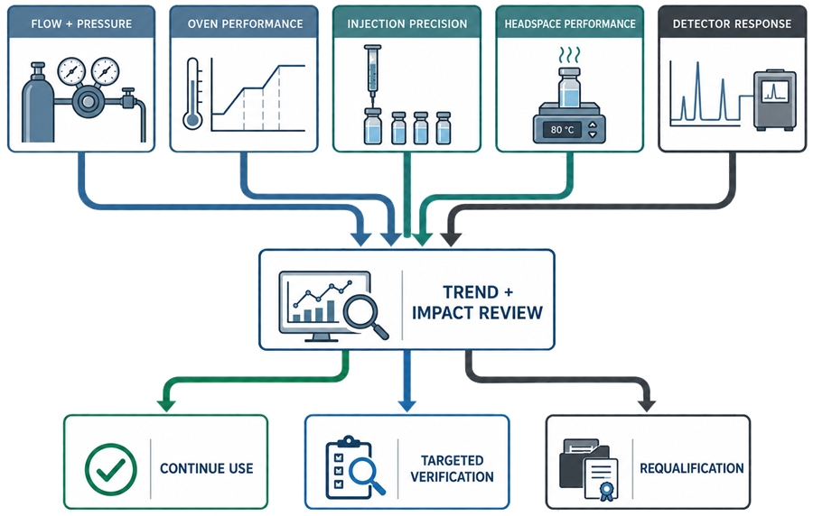
Routine evidence should be reviewed for:
- gradual drift
- increasing variability
- recurring leaks
- increasing gas consumption
- worsening injection precision
- temperature instability
- detector-response decline
- increasing noise or drift
- recurring headspace carryover
- repeated failed system suitability
- repeated service interventions
An individual result may remain within its limit while contributing to an adverse trend.
Qualification and Verification Intervals
No single qualification interval is appropriate for every GC or headspace system. Intervals should consider:
- intended use
- data criticality
- detector type
- headspace use
- system complexity
- frequency of use
- method sensitivity
- routine system suitability
- calibration history
- failure history
- maintenance history
- supplier recommendations
- environmental conditions
- previous qualification performance
- change frequency
Some activities may be scheduled periodically. Others should be event-driven or supported through routine performance checks and trend review.
The program should define which tests are performed, their frequency, acceptance criteria, failure response, and relationship to calibration and requalification.
Preventive Maintenance
GC and headspace maintenance may include:
- gas regulators
- gas purifiers and traps
- inlet septa
- inlet liners
- inlet seals
- gold seals
- split vent traps
- gas valves
- pressure and flow controllers
- autosampler syringes
- wash stations
- injection towers
- oven fans and sensors
- column connections
- detector jets
- detector collectors
- detector lamps or filaments where applicable
- FID ignition components
- headspace needles
- sample loops
- headspace valves
- transfer lines
- vial-handling mechanisms
- incubation-oven components
- workstations and data storage
Maintenance frequency should reflect use, sample matrix, detector type, gas quality, contamination, supplier recommendations, and failure history.
Post-maintenance testing should be selected according to the function affected.
Common Failure Modes
Gas-system failures
- depleted carrier gas
- regulator malfunction
- contaminated or exhausted trap
- moisture or oxygen intrusion
- incorrect gas
- line leakage
- pressure instability
- flow-controller failure
Inlet and injection failures
- leaking septum
- contaminated liner
- damaged seal
- blocked split vent
- syringe wear
- needle blockage
- poor injection precision
- carryover
- incorrect inlet mode
Oven and column failures
- temperature bias
- temperature instability
- incorrect ramp
- cooling failure
- fan failure
- column leak
- column contamination
- column degradation
- incorrect column installation
Headspace failures
- incubation-temperature error
- inadequate equilibration
- agitation failure
- leaking vial
- pressurization failure
- needle blockage
- loop contamination
- valve leakage
- transfer-line condensation
- carryover
- poor vial-to-vial precision
- GC synchronization failure
Detector failures
- FID flameout
- incorrect detector-gas flow
- contaminated detector
- response loss
- excessive noise
- excessive drift
- TCD filament failure
- ECD response decline
- MS vacuum or tune failure
Data-system failures
- interrupted acquisition
- incorrect instrument configuration
- unauthorized method change
- uncontrolled integration
- failed calculation
- failed interface
- unavailable storage
- incomplete backup
- time mismatch
- audit-trail deficiency
Recurring failures should be reviewed collectively rather than treated only as isolated maintenance events.
Change and Requalification
Potential requalification triggers include:
- relocation
- carrier-gas change
- regulator or gas-line modification
- electronic pressure-controller replacement
- inlet replacement
- major autosampler repair
- syringe-system change
- oven sensor or controller replacement
- detector replacement
- major detector repair
- headspace oven repair
- sampling-needle replacement where performance may be affected
- sample-loop or valve replacement
- transfer-line replacement
- workstation or server replacement
- software or firmware upgrade
- interface change
- repeated performance failure
- unresolved adverse trend
- expansion to a more demanding intended use
The impact assessment should determine whether the appropriate response is:
- routine operational check
- calibration
- leak testing
- targeted functional verification
- detector performance testing
- headspace precision testing
- carryover testing
- targeted PQ
- software regression testing
- interface testing
- partial requalification
- broader requalification
The analytical instrument requalification framework should determine scope rather than automatically repeating the entire original qualification.
Return to Service
Return-to-service evidence may include:
- maintenance completion
- correct component installation
- leak test
- gas pressure and flow verification
- calibration
- inlet verification
- oven-temperature verification
- temperature-program verification
- injection precision
- headspace precision
- carryover
- detector-response check
- communication check
- software regression test
- system suitability
- approved release
A supplier service report confirming completion of repair is not sufficient by itself. The laboratory should confirm that affected GMP functions and data controls remain acceptable.
Common Qualification Deficiencies
Common deficiencies include:
- qualifying the GC but excluding the headspace sampler
- treating the headspace sampler as a simple autosampler
- omitting gas purity and trap controls
- verifying displayed pressure without independent evidence
- failing to test leak integrity
- testing only static oven temperature
- omitting programmed temperature ramps
- applying one detector protocol to every detector type
- failing to verify sample-loop and transfer-line temperatures
- using one vial repeatedly to represent headspace precision
- using an inadequate carryover challenge
- ignoring vial closure and leak effects
- omitting GC–headspace synchronization testing
- failing to verify data-acquisition rate for narrow peaks
- treating system suitability as a substitute for qualification
- accepting supplier OQ documents without applicability assessment
- returning the system to use without targeted post-maintenance testing
- reviewing recurring leaks or precision failures only as isolated events
- failing to retain original chromatograms, metadata, integration history, and audit trails
Conclusion
GC and headspace qualification should demonstrate control of the complete analytical system, from gas supply and sample introduction through temperature-controlled separation, detection, data acquisition, processing, review, and electronic-record retention.
The qualification strategy should distinguish the GC and headspace functions while verifying their integrated operation. Carrier-gas control, leak integrity, oven programming, injection performance, headspace incubation and transfer, detector response, software, and data integrity all contribute to reliable analytical results.
Continued fitness for use depends on calibration, system suitability, routine checks, preventive maintenance, failure investigation, performance trending, change control, and proportionate requalification throughout the system lifecycle.