

Clean Steam System Design and Quality Attributes
Clean steam system design must do more than produce vapor at the required pressure. It must establish and preserve the chemical and physical qualities needed at each GMP point of use while controlling entrainment, condensate accumulation, noncondensable gases, superheat, contamination, unstable demand, and equipment-interface risks.
A defensible design begins with intended use. Steam used for sterilization-in-place, a moist-heat sterilizer, direct product contact, or cleanroom humidification may not require identical attributes, sampling locations, capacity margins, or controls. The system must therefore connect each application to defined requirements, then translate those requirements into generator, distribution, drainage, instrumentation, sampling, capacity, and redundancy decisions.
Purpose and Scope
This article addresses the design and quality-attribute definition of clean steam systems used in pharmaceutical, biotechnology, and other regulated GMP applications. It covers:
- Feed-water selection and control
- Clean steam generation
- Separation of droplets and control of carryover
- Hygienic materials and fabrication
- Distribution architecture
- Drainage, condensate removal, and steam traps
- Point-of-use and equipment interfaces
- Chemical and physical steam-quality attributes
- Condensate and physical-quality sampling provisions
- Instrumentation, automation, alarms, and data needs
- Capacity, diversity, turndown, and redundancy
- Maintainability and lifecycle design evidence
Application selection and the boundary between clean steam and plant steam are addressed in Clean Steam Systems for GMP Applications. Qualification execution, routine monitoring, change assessment, and requalification are addressed in Clean Steam System Qualification, Monitoring, and Requalification.
This article does not prescribe one universal system arrangement or one specification for every clean steam use. The approved design basis must reflect intended application, product and process risk, applicable compendial requirements, sterilizer or process-equipment needs, site standards, and regulatory commitments.
Clean Steam, Pure Steam, and the Design Basis
“Clean steam” is an engineering and GMP term commonly used for steam generated and distributed under controlled conditions for applications where steam or condensate quality matters. “Pure Steam” is an official USP article with defined source-water and condensate requirements. A clean steam system may be designed to produce condensate meeting the USP Pure Steam monograph, but that status should not be assumed from the equipment name.
The USP Pure Steam monograph defines Pure Steam as water vaporized in a manner that prevents source-water entrainment. It permits specified drinking-water sources, contains no added substance, and states that saturation or dryness and noncondensable-gas requirements are determined by the application. Site requirements may be more restrictive. For example, a facility may require Purified Water or WFI feed, bacterial-endotoxin control, a defined dryness value, limits for noncondensable gases or superheat, or application-specific condensate criteria.
The design basis should identify, for every use:
- Whether steam or resulting condensate contacts product
- Whether it contacts product-contact or sterile-path surfaces
- Whether it is the sterilizing medium
- Whether condensate can remain after the operation
- Required delivery pressure, temperature, and flow
- Minimum and maximum demand
- Required chemical condensate quality
- Whether bacterial endotoxins must be controlled
- Required saturation, dryness, noncondensable-gas, or superheat characteristics
- Required warm-up, exposure, and recovery performance
- Permitted plant-steam or other utility interfaces
- Sampling and monitoring expectations
- Consequences of interruption or quality failure
Selection of Purified Water, WFI, or another justified feed-water quality should follow the intended-use principles in Pharmaceutical Water Quality Categories and Intended Use.
System Boundary and Design Responsibilities
The clean steam boundary should be defined before detailed design. A typical boundary begins at the approved feed-water connection and includes the generator, separator, controls, clean-side distribution, condensate-removal devices, branches, sampling assemblies, and defined points of delivery. It may also include portions of connected equipment when those components influence delivered steam quality or drainage.
The design record should identify interfaces with:
- Feed-water generation and distribution
- Plant steam or another heating medium supplied to the generator
- Electrical power and instrument air
- Cooling water serving sample coolers or auxiliary equipment
- Drains and condensate recovery systems
- Sterilizers and autoclaves
- SIP circuits and process vessels
- HVAC humidification systems
- Building-management or utility-monitoring systems
- Equipment controls and data historians
The P&IDs and boundary narrative should distinguish clean-side components from plant-utility components. A plant-steam-to-clean-steam generator requires a defined barrier between the heating medium and the clean side. Heat-exchanger or tube failure must be considered because a pressure differential can drive the lower-quality utility into the clean steam or feed-water side.
Responsibility boundaries also require definition. The utility owner may control the header, while manufacturing or equipment owners control final branches, traps, valves, or sterilizer piping. Qualification and maintenance gaps frequently occur when a component lies physically between systems but is not assigned to either owner.
The general GMP classification of utility boundaries and direct or indirect impact is discussed in Utility Systems in GMP Manufacturing.
Clean Steam Generator and Distribution Overview
The existing illustration should remain in this location without modification.
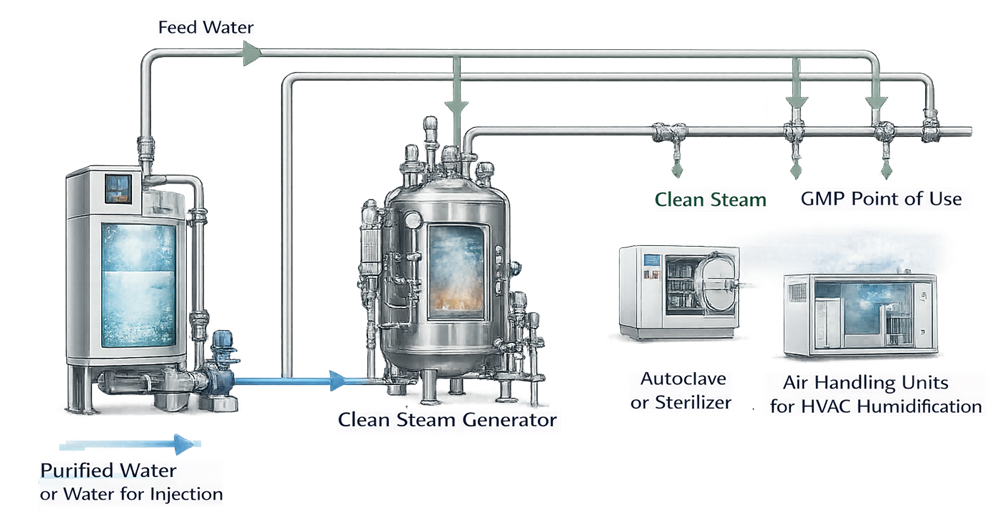
The illustration shows the functional relationship among feed water, steam generation, distribution, condensate removal, and GMP users. Actual designs may use different generation technologies, header arrangements, pressure-reduction strategies, and redundancy configurations.
Feed-Water Quality and Supply Design
The generator cannot consistently produce acceptable clean steam if its feed-water supply is unstable, contaminated, or incompatible with the generator design. Feed-water selection should consider both condensate requirements and generator reliability.
Potential feed sources include Drinking Water meeting applicable requirements, Purified Water, or WFI. The USP Pure Steam monograph permits specified drinking-water sources, but this does not make potable water the correct choice for every GMP application. Feed-water quality should be selected from intended use, endotoxin risk, generator technology, expected carryover control, site procedures, approved filings, and the quality required at use points.
The feed-water design should address:
- Chemical and microbial quality
- Bacterial-endotoxin loading where relevant
- Hardness, silica, chlorides, and other constituents affecting scaling or corrosion
- Dissolved gases that may contribute to noncondensable gases
- Seasonal and source-water variability
- Supply pressure and temperature
- Minimum and maximum available flow
- Feed interruptions and recovery
- Backflow prevention
- Stagnation between the water system and generator
- Sampling and monitoring at the feed interface
Where Purified Water or WFI provides feed, the connection should preserve the control strategy of the water system. Branch length, use frequency, circulation, flush arrangements, sanitization, and backflow control should be considered. Detailed water-generation and distribution principles are addressed in Pharmaceutical Water System Design and Distribution.
A feed-water tank or break tank may stabilize supply but also creates a stored-water risk. Its need, hygienic design, venting, turnover, temperature, drainage, sanitization, and monitoring should be justified. A poorly controlled feed tank can defeat the quality provided by the upstream water system.
Clean Steam Generation
Clean steam may be generated by a dedicated unit using plant steam, electricity, or another energy source. Multi-effect or other configurations may be used when they meet the intended capacity and quality requirements. The technology name alone does not establish suitability.
Evaporation and Separation
The generator should vaporize feed water and separate vapor from liquid droplets. Entrainment is important because droplets can carry nonvolatile feed-water contaminants, endotoxins, treatment residues, and particulates into the clean steam distribution system.
Separation may rely on disengagement space, controlled vapor velocity, baffles, cyclonic action, demisters, or other proven features. The design should be effective through the approved operating range, not only at a nominal load. High demand, rapid load changes, foaming, abnormal feed conditions, high liquid level, or inadequate blowdown can increase carryover risk.
The generator design should define:
- Normal and allowable water level
- Level-control method and protective interlocks
- Feed-water control response
- Evaporation capacity and turndown
- Separator design and maximum vapor loading
- Blowdown method and operating basis
- Start-up and warm-up sequence
- High-pressure and low-pressure protection
- High-level, low-level, and feed-failure responses
- Conductivity or other feed/blowdown monitoring where justified
- Safe shutdown and recovery behavior
Plant-Steam Heating Interface
Where plant steam supplies energy through a heat exchanger, the heating side should remain physically isolated from the clean side. Materials, tube or plate configuration, pressure relationships, leak detection, inspection access, and response to suspected failure should be defined.
A double-tube-sheet or double-barrier arrangement may provide additional protection or leak indication, but it is not automatically required for every generator. The selected barrier should be based on the consequence and detectability of cross-contamination, applicable code, equipment construction, pressure differential, and maintenance strategy.
Blowdown and Concentration Control
As water evaporates, nonvolatile material concentrates in the generator. Blowdown removes concentrated liquid and helps control scaling, foaming, and carryover. The blowdown rate should be established from feed-water quality, generator design, operating load, and supplier data. Excessive blowdown wastes energy and water; inadequate blowdown can impair quality and reliability.
Blowdown piping should discharge safely, drain freely, resist thermal stress, and avoid backpressure that can interfere with generator operation. Where blowdown is automated, the initiating measurement, setpoint, valve action, alarm, and failure position should be specified.
Materials, Fabrication, and Hygienic Construction
Clean-side materials must be compatible with steam, condensate, feed water, cleaning or passivation chemicals, temperature cycling, and the required condensate quality. Austenitic stainless steel is commonly used, but the alloy grade, product-contact definition, surface finish, welding standard, gasket material, and documentation should be specified rather than assumed.
Design and construction requirements may include:
- Defined stainless-steel grade and component specifications
- Controlled internal surface finish where justified
- Hygienic tube and fitting geometry
- Weld procedures and welder qualifications
- Weld identification, inspection, and acceptance criteria
- Boroscope or other internal inspection scope
- Control of weld discoloration and oxidation
- Passivation and post-passivation rinsing
- Compatible valves, gaskets, diaphragms, traps, and instruments
- Traceable material and fabrication records
- Cleaning and preservation before turnover
ASME BPE provides recognized design and fabrication requirements for high-purity bioprocessing equipment and piping. Its application should be defined in project requirements; citing “BPE construction” without specifying the applicable edition, sections, classifications, and acceptance criteria is insufficient.
Elastomers and valve diaphragms require particular attention because repeated steam exposure can cause hardening, creep, cracking, shedding, or loss of sealing. Design review should confirm temperature ratings, replacement access, expected service life, and inspection or preventive-maintenance provisions.
Distribution Architecture
The distribution system must deliver steam within the pressure, flow, and quality envelope required by all users. The design may use a main header with branches, multiple pressure zones, dedicated subheaders, or local pressure reduction. The arrangement should minimize condensate accumulation and unstable pressure while allowing isolation and maintenance.
Distribution design should address:
- Header size and vapor velocity
- Pressure drop at peak and minimum demand
- Main and branch slope
- Thermal expansion and pipe support
- Condensate collection and removal
- Branch orientation and takeoff geometry
- Pressure-reducing stations
- Isolation valves and drainage of isolated sections
- Warm-up and start-up condensate load
- Low-use and future branches
- Dead-ended sections
- Cross-connection prevention
- Accessible sampling locations
- Safe maintenance and lockout
Oversizing is not automatically conservative. An oversized header may increase warm-up time, surface area, heat loss, and condensate formation and may perform poorly at low loads. Undersizing can cause excessive pressure drop, high velocity, erosion, unstable control, and wet steam. Sizing should consider the full demand profile rather than only a single peak-flow number.
Insulation should limit heat loss and personnel exposure while allowing inspection where needed. Jacket and insulation materials should suit the surrounding area, cleaning regime, corrosion risk, and classified-space requirements. Insulation does not replace correct drainage.
Drainability and Condensate Control
Steam condenses during warm-up and whenever heat is lost from the distribution system. Condensate must be removed without allowing steam loss, water hammer, flooding, or stagnant liquid. Effective drainage is therefore a functional requirement, not merely a piping preference.
The existing illustration should remain in this location without modification.
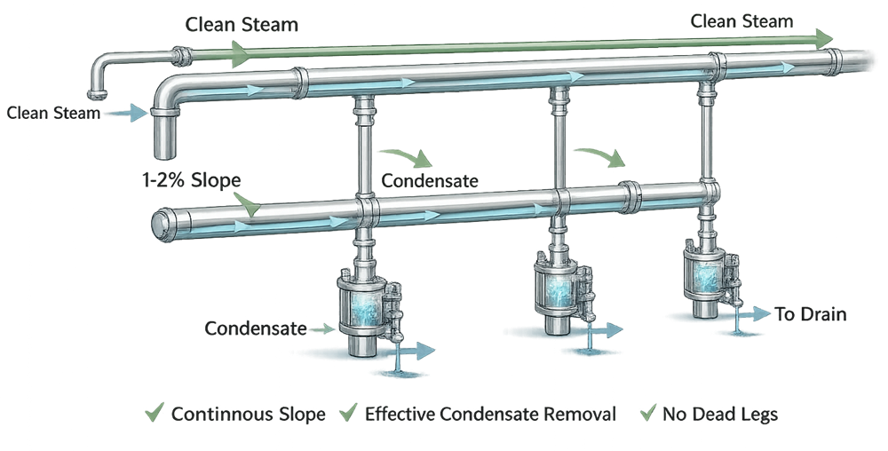
Slope and Low Points
Piping should slope continuously toward defined condensate-removal points under installed and operating conditions. The design must consider construction tolerances, pipe support, thermal expansion, settlement, seismic restraints, and branch geometry. A slope value on a drawing is not sufficient if field routing creates unintended pockets.
Low points should be deliberate, drainable, accessible, and represented on the P&ID or isometric drawings. Valves and reducers should be oriented so they do not create liquid traps. Isolation of a branch should not leave an undrainable volume that later discharges condensate into a user.
Steam Traps and Drip Legs
Steam traps should suit clean service, expected condensate load, pressure differential, start-up air removal, orientation, and maintenance access. Trap selection should consider:
- Maximum start-up and steady-state condensate load
- Ability to discharge air and noncondensable gases
- Minimum operating differential pressure
- Failure mode and detectability
- Cleanability and internal retention
- Installation orientation
- Upstream collection volume
- Downstream backpressure
- Inspection, testing, and replacement access
A trap that is correct in principle can fail in application when installed without adequate collection volume, with a closed downstream valve, against excessive backpressure, or where condensate must rise after discharge.
Condensate Disposition
Condensate from clean steam should be directed to a controlled drain or a specifically designed recovery system. It should not be returned automatically to a clean feed-water or clean steam system merely because its origin is clean. Recovery introduces risks from connected equipment, traps, drains, backpressure, contamination, and mixed users. Energy recovery may be feasible through an isolated heat exchanger or a designed condensate system after documented assessment.
Condensate discharge must not create an open path for drain contamination, aerosols, or backflow into the clean steam system. Air gaps, break tanks, closed recovery, and other arrangements should be selected according to the pressure and contamination risks.
Point-of-Use and Equipment Interfaces
The point of use is where utility design and process-equipment design meet. Delivered steam may be unacceptable even when the header is well controlled if the final branch, valve, hose, pressure regulator, trap, or equipment inlet retains condensate or introduces contamination.
The interface specification should define:
- Delivery pressure and allowable variation
- Required flow throughout the operating cycle
- Branch warm-up and drainage
- Valve and regulator arrangement
- Sampling location relative to the user
- Condensate discharge path
- Backflow and reverse-pressure protection
- Equipment isolation and maintenance boundary
- Responsibility for instruments and traps
- Required alarm or permissive signals
Sterilizers and Autoclaves
Sterilizer performance can be affected by saturation, dryness, noncondensable gases, superheat, pressure stability, and supply capacity. The steam-supply design should be coordinated with chamber manufacturer requirements, load types, air-removal method, cycle demand, and applicable moist-heat sterilization standards.
Physical steam-quality criteria used for a sterilizer should not automatically be imposed on every process use, and a condensate chemistry result does not demonstrate acceptable sterilizer steam behavior. ISO 17665:2024 provides the current general framework for development, validation, and routine control of moist-heat sterilization processes for medical devices; other applicable standards and regulatory expectations may also govern the specific sterilizer application.
Sterilization-in-Place
SIP performance depends on the integrated steam path through the process equipment. Supply pressure alone does not demonstrate that all locations receive saturated steam or that air and condensate are removed. Equipment geometry, venting, trap capacity, drain location, control-valve response, noncondensable gases, and cold spots must be addressed with the process-equipment design. The relationship between the utility and the sterilized circuit is discussed in Steam-in-Place (SIP) Utility Systems.
HVAC Humidification
Clean steam used for direct injection into supply air should be evaluated for condensate chemistry, additive absence, particulate or corrosion products, dispersion, absorption distance, droplet carryover, duct wetting, and microbial consequences. The humidifier assembly and steam separator should prevent liquid water from entering or collecting in the air-handling system. Drain pans or duct drainage should not be treated as compensation for an inadequately designed injection system.
Indirect Heating
Where steam is separated from product or a clean utility by a heat exchanger, the design assessment should evaluate barrier integrity, pressure differential, leak detection, failure response, and whether contamination can reach the protected side. Plant steam may be acceptable on the heating side when the barrier and failure controls are adequate; clean steam is not automatically required for every indirect heating duty.
Clean Steam Quality Attributes
Quality attributes should be assigned to the application and verified at representative locations. They fall into two related but distinct groups:
- Condensate attributes, which assess material carried with the steam after condensation.
- Physical steam attributes, which assess suitability of the vapor as a heat-transfer or sterilizing medium.
The existing illustration should remain in this location without modification.
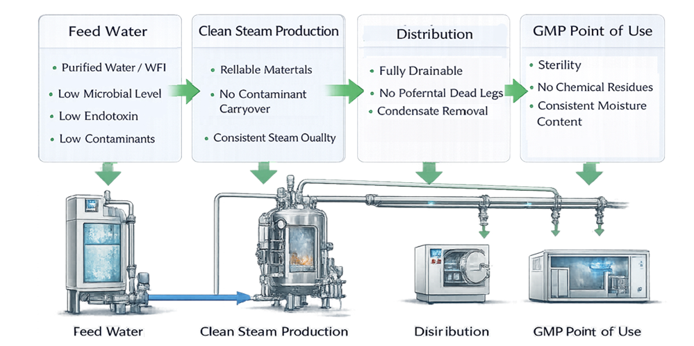
| Quality attribute | What it indicates | Principal design influences | Applicability |
|---|---|---|---|
| Conductivity | Ionic contamination in condensate | Feed water, entrainment, corrosion, contamination, sampling | Common condensate requirement when USP or site criteria apply |
| Total organic carbon | Organic contamination in condensate | Feed water, carryover, materials, residues, sampling | Common condensate requirement when USP or site criteria apply |
| Bacterial endotoxins | Pyrogenic contamination risk | Feed-water endotoxin, entrainment, system contamination, sampling | Required where specified by monograph, process, product, or site risk assessment |
| Appearance or visible residue | Gross contamination or carryover | Generator separation, corrosion, construction residue | Supporting observation; not a substitute for analytical tests |
| Saturation relationship | Whether temperature and pressure are consistent with saturated steam | Pressure control, heat loss, superheat, measurement accuracy | Important for heat-transfer and sterilization applications |
| Dryness | Fraction of steam mass present as vapor rather than entrained liquid | Generator separation, drainage, insulation, demand, pressure reduction | Application-dependent; especially relevant to sterilizers and some SIP uses |
| Noncondensable gases | Air or other gases that can impair steam contact and heat transfer | Feed-water gases, air ingress, venting, start-up, generator operation | Application-dependent; important where air removal and heat transfer are critical |
| Superheat | Steam temperature above saturation at the measured pressure | Pressure reduction, dry heat input, low moisture, measurement location | Application-dependent; excessive superheat may impair moist-heat performance |
| Pressure and flow stability | Ability to support the user cycle | Capacity, controls, header sizing, simultaneous demand | Required for all uses, with application-specific limits |
Chemical Condensate Quality
Chemical condensate requirements should be stated explicitly. Where the system claims USP Pure Steam, the applicable official monograph governs. Site requirements may add endotoxin, microbial, particulate, elemental, or other tests when justified by the use and risk.
Condensate is not identical to the vapor at the instant of use. Sampling condenses steam and can introduce contamination from the valve, tubing, condenser, cooling water leak, container, environment, or collection technique. The method and apparatus must therefore be designed to produce a representative sample.
Physical Steam Quality
Physical steam quality cannot be inferred from conductivity or TOC. Dryness, noncondensable gases, saturation, and superheat address different failure mechanisms and may require specialized field tests.
Acceptance criteria should come from the application, equipment requirements, applicable standard, process development, and qualification strategy. FDA’s current biological drug-substance inspection program directs investigators to determine whether saturation or dryness, noncondensable gases, and superheat are suitable for the intended pure-steam application. It does not establish one numerical criterion for every clean steam system.
Sampling-System Design
Sampling capability should be designed with the utility, not improvised during qualification. The sampling plan should distinguish condensate chemistry sampling from physical steam-quality testing because the equipment, location, and operating conditions differ.
Condensate Sampling
A condensate sampling assembly should:
- Represent the steam supplied to the intended user
- Use compatible, cleanable materials
- Drain completely after use
- Avoid retained water and contamination traps
- Permit safe pressure reduction and cooling
- Control cooling-water cross-contamination risk
- Support reproducible flushing and collection
- Protect personnel from steam and hot condensate
- Provide sufficient sample volume without destabilizing the header
- Allow documented identification of location and collection conditions
A permanently installed sample cooler may improve consistency but requires hygienic design, drainage, maintenance, and leak control. A portable condenser may be appropriate when its cleaning, assembly, transport, storage, and connection are controlled. Neither arrangement is inherently superior.
Sampling directly from a trap discharge may not represent the steam delivered to a user because the condensate can include material accumulated in the drip leg or branch. Conversely, a header sample may fail to represent a long, low-use, or pressure-reduced branch. Locations should be selected from the distribution design and risk assessment.
Physical-Quality Test Connections
Dryness, noncondensable-gas, and superheat testing may require dedicated connection geometry, adequate straight run, stable pressure, safe discharge, and sufficient flow. The design team should confirm these needs before fabrication. A connection that is convenient for condensate chemistry may be unsuitable for physical-quality testing.
The system should support testing at representative worst-case conditions, such as remote locations, low-pressure zones, large users, or points affected by pressure reduction and simultaneous demand.
Instrumentation, Automation, and Alarms
Instrumentation should demonstrate and control the parameters that matter to generator protection, delivery performance, and quality. Instrument quantity should be driven by control and evidence needs, not by a presumption that every variable requires continuous recording.
Potential measurements include:
- Feed-water pressure, temperature, flow, conductivity, or quality status
- Generator water level
- Clean steam pressure and temperature
- Plant-steam or heating-medium pressure
- Generator output or calculated load
- Blowdown conductivity, flow, or valve status
- Header pressure at critical or remote locations
- Pressure upstream and downstream of reducing stations
- Condensate temperature or trap performance indicators
- Utility availability and standby-generator status
Alarms and protective functions may include:
- High or low generator water level
- Loss of feed water
- High or low clean steam pressure
- Heating-medium failure
- Excessive feed or blowdown conductivity where applicable
- Control-valve failure or abnormal position
- Standby-unit failure to start
- Instrument failure or signal loss
- Communication or historian failure where data are relied upon
Each GMP-relevant instrument should have a defined range, accuracy, location, calibration strategy, tag, data owner, and relationship to operating or quality decisions. Sensor location matters: a pressure transmitter at the generator may not detect unacceptable pressure loss at a remote user.
Automation requirements should define sequences, permissives, interlocks, alarm delays, fail-safe states, user access, data retention, time synchronization, backup, and recovery as applicable. Requirements should be traceable from the approved URS for GMP Facilities, Utilities, and Equipment through design and qualification evidence.
Capacity, Demand, Turndown, and Redundancy
Capacity should be based on a documented demand model rather than the sum of every nameplate maximum or an unsupported diversity factor. The model should include:
- Normal production demand
- Maximum credible simultaneous demand
- Sterilizer and SIP cycle profiles
- Warm-up and start-up peaks
- Header and branch heat losses
- Future approved expansion
- Minimum stable demand
- Generator turndown and cycling behavior
- Pressure losses at the most demanding user
- Condensate load during start-up
- Recovery after a large user opens or closes
Cycle timing matters. Two users with equal total consumption can impose very different requirements if one draws steam steadily and the other creates a short high-flow peak. The design should use time-based demand profiles where batch cycles, sterilizers, or SIP sequences dominate load.
Operating at very low demand can be as problematic as peak demand. Frequent cycling, unstable level control, wet steam, excess pressure variation, and poor separation may occur when a large generator operates below its effective turndown. Multiple smaller units or staged control may provide better operating coverage, but increase valves, controls, maintenance, and qualification scope.
Redundancy should reflect business continuity and product-quality risk. N+1 capacity is not a universal GMP requirement. The design assessment should evaluate:
- Consequence of complete loss of clean steam
- Maximum acceptable outage
- Ability to stop processes safely
- Product or equipment hold-time limits
- Time to repair or obtain critical parts
- Whether one unit can support essential loads
- Automatic or manual changeover
- Common-mode failures in feed water, plant steam, power, controls, or headers
- Maintenance isolation without contaminating or depressurizing the operating unit
- Testing and exercising of standby equipment
Nominally redundant generators do not provide independent capacity when they share an undersized feed line, one control panel, one heating-medium supply, one distribution header without isolation, or a single unmaintainable pressure-reduction station. Redundancy claims should be verified at the complete utility level.
Maintenance, Inspection, and Access by Design
The system should permit maintenance without creating avoidable contamination or lengthy uncontrolled recovery. Design review should confirm access for:
- Generator inspection and internal cleaning
- Separator and demister inspection where applicable
- Instrument calibration and replacement
- Safety-valve testing
- Steam-trap inspection and testing
- Valve and diaphragm replacement
- Sampling assembly cleaning or replacement
- Heat-exchanger integrity testing
- Weld and support inspection
- Blowdown maintenance
- Insulation removal and restoration where required
Isolation points should allow safe work and controlled return to service. Temporary piping, jumpers, or unplanned open breaks should not be the routine maintenance strategy. Components expected to be replaced should be located and oriented so replacement does not alter slope, introduce excessive dead space, or require uncontrolled fabrication.
Spare-part specifications should preserve materials, surface finish, temperature rating, elastomer compatibility, control configuration, and hygienic geometry. A mechanically interchangeable part may not be equivalent for a clean steam application.
Design Review and Qualification Readiness
Design Qualification should confirm that the proposed system can meet approved requirements before construction or purchase commitments make correction difficult. General DQ methods are described in Design Qualification (DQ) for GMP Systems and Equipment.
The review should evaluate:
- Intended-use matrix and quality attributes
- System boundary and owner responsibilities
- Feed-water basis and variability
- Generator capacity, turndown, and separation
- Distribution pressure-drop calculations
- Slope, drainage, and trap strategy
- Materials, fabrication, welding, and passivation
- Point-of-use and equipment interfaces
- Sampling and physical-test connections
- Instrumentation and control philosophy
- Alarm and failure responses
- Capacity, diversity, and redundancy
- Maintainability, spares, and obsolescence
- Applicable codes, standards, and regulatory commitments
- Commissioning and qualification testability
Design outputs should include, as applicable:
- Approved URS and design basis
- Process-flow diagram and P&IDs
- System-boundary drawing
- Intended-use and point-of-use schedule
- Steam-quality attribute matrix
- Heat and mass balance
- Demand profile and capacity calculations
- Pressure-drop and pipe-sizing calculations
- Drainage and trap schedule
- Instrument list and calibration requirements
- Alarm list and cause-and-effect matrix
- Materials, surface-finish, and weld specifications
- Sampling-location and test-connection plan
- Equipment-interface requirements
- Maintenance and spare-parts strategy
- Requirements traceability matrix
- Design-review actions and resolution records
Unresolved design risks should not be transferred silently into qualification. Qualification can verify that the installed system meets an adequate design; it is not an efficient substitute for correcting a design that cannot support drainage, sampling, capacity, or required steam quality.
Common Design Weaknesses
Recurring weaknesses include:
- Specifying “clean steam” without defining intended applications or attributes
- Assuming all clean steam must use WFI feed, or assuming potable feed is always adequate
- Treating USP condensate compliance as proof of physical steam quality
- Applying sterilizer criteria to every use without justification
- Ignoring endotoxin loading and entrainment risk
- Sizing only for average demand or nameplate peak demand
- Failing to evaluate minimum-load operation and turndown
- Installing oversized headers without a drainage and low-load assessment
- Using convenient rather than representative sample locations
- Omitting connections needed for physical-quality testing
- Leaving final equipment branches outside the utility boundary
- Poor slope, unintended low points, or inaccessible traps
- Returning condensate without a contamination-risk assessment
- Claiming redundancy while retaining common-mode failures
- Locating instruments where they cannot detect remote-user conditions
- Selecting components that cannot be maintained without changing hygienic geometry
- Relying on downstream equipment to compensate for wet, unstable, or contaminated steam
These conditions should be corrected through requirements, design review, construction controls, and commissioning rather than accepted as permanent qualification exceptions.
Lifecycle Position
The approved design establishes the baseline for installation verification, functional challenges, steam-quality testing, monitoring, maintenance, change control, and requalification. Design calculations and risk decisions should remain available throughout the system lifecycle because future changes may alter demand, pressure distribution, drainage, sampling representativeness, control performance, or redundancy.
Utility performance, maintenance history, alarms, changes, adverse trends, and periodic-review outcomes are addressed in Utility System Lifecycle Control and Monitoring. Changes to generators, distribution, points of use, controls, feed water, capacity, or intended applications should be assessed under Utility Change Control and Requalification.
Summary
An effective clean steam design connects intended use to measurable quality attributes and then provides the equipment, distribution, drainage, sampling, instrumentation, capacity, and lifecycle features needed to preserve those attributes at each point of use.
The principal design conclusions are:
- Clean steam and USP Pure Steam claims must be defined, not assumed.
- Feed-water quality must be suitable for the intended condensate and application risk.
- Generator separation must control entrainment throughout the operating range.
- Distribution sizing must address peak demand, minimum load, pressure loss, and condensate formation.
- Continuous drainage and correctly applied steam traps are essential functional controls.
- Condensate chemistry and physical steam quality answer different questions.
- Sampling and physical-test connections must be designed before qualification.
- Instrumentation must represent the conditions that matter at critical users.
- Capacity and redundancy must be evaluated at the complete utility level, including common-mode failures.
- Design evidence must support qualification and later lifecycle decisions.