

Compressed Air Systems for GMP Manufacturing
Purpose and Scope
Compressed air supports equipment operation, process control, material handling, cleaning, drying, and product manufacturing throughout pharmaceutical and biopharmaceutical facilities. Its GMP significance does not arise from the name of the utility. It arises from how the air is generated, conditioned, distributed, and used, and from whether a loss of pressure or air-quality control could affect product quality, a product-contact surface, a sterile boundary, data reliability, or personnel safety.
This article establishes the technical and regulatory framework for compressed-air systems used in GMP manufacturing. It addresses:
- Instrument air, process air, product-contact air, and breathing air
- Intended-use and product-impact classification
- System architecture and boundaries
- Particles, water, oil, microorganisms, and gaseous contaminants
- Application of ISO 8573 purity classes and test methods
- User requirements and point-of-use specifications
- Compressor, dryer, filtration, receiver, and distribution design
- Point-of-use controls and equipment interfaces
- Capacity, turndown, recovery, and redundancy
- Instrumentation, alarms, sampling provisions, and data needs
- Maintenance activities and temporary configurations that can place air quality at risk
- Design evidence needed for qualification and continued lifecycle control
The article focuses on the system and design basis. Detailed execution of qualification, routine monitoring, periodic review, and requalification is addressed in Qualification, Monitoring, and Requalification of Gas Utilities.
Compressed Air as a GMP Utility
Compressed air is normally generated on site from ambient air. The generation train raises pressure and removes heat, liquid water, particles, oil, and other contaminants before the air enters storage and distribution. The system may serve hundreds of use points with different functions and different potential consequences of failure.
Unlike a purchased process gas supported by a supplier certificate, on-site compressed air is continuously manufactured by an interconnected facility system. Its quality can change because of intake conditions, compressor condition, cooling performance, separator efficiency, dryer operation, filter loading, condensate-drain failure, distribution corrosion, demand changes, maintenance, or an abnormal operating lineup. A satisfactory result at one sample point does not establish that every use point is suitable.
The general classification and lifecycle principles for pharmaceutical utilities are described in Utility Systems in GMP Manufacturing. For compressed air, those principles require a use-point inventory, defined system boundaries, documented quality requirements, suitable engineered controls, and evidence that the delivered air remains fit for each approved use.
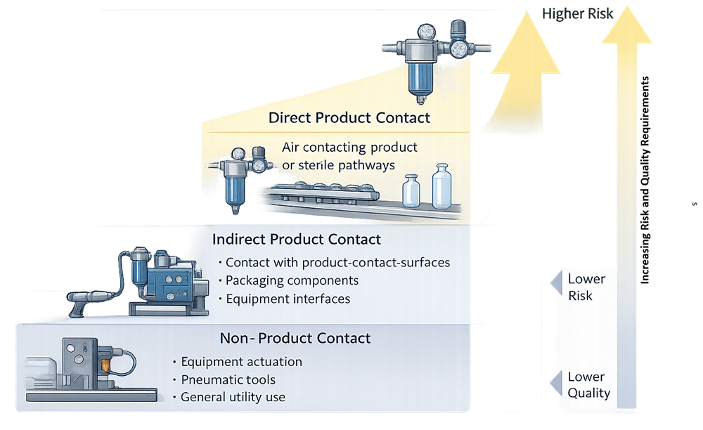
Compressed air should not automatically be classified as either a direct-impact or indirect-impact utility for the entire facility. A common header may supply non-GMP pneumatic tools, critical instrument actuators, equipment-cleaning stations, and air that directly contacts exposed product. The appropriate control strategy must therefore consider both the central system and each materially different use-point category.
Functional Types of Compressed Air
The terms instrument air, process air, product-contact air, and breathing air describe different aspects of use. They should not be treated as four mutually exclusive quality grades.
Instrument Air
Instrument air operates pneumatic valves, actuators, cylinders, positioners, dampers, and control devices. In many applications, the air remains physically separated from product and product-contact surfaces by equipment construction. Its principal requirements may therefore be reliable pressure, adequate flow, freedom from damaging liquid water and oil, and cleanliness sufficient to protect instruments and controls.
Instrument air can still have significant GMP impact. Loss of pressure may move a valve to an unsafe position, interrupt a critical process, defeat an isolation function, or prevent a control loop from maintaining an approved parameter. A leaking diaphragm, actuator interface, or air-to-product barrier may also create an unexpected contamination path. System classification must consider the failure position, barrier design, detectability, and process consequence rather than assuming that all instrument air is low risk.
Process Air
Process air performs a manufacturing or equipment function. Examples include:
- Drying cleaned equipment, components, granules, or product-contact parts
- Agitating, conveying, fluidizing, atomizing, or aerating material
- Purging equipment or process spaces
- Operating air knives or blow-off devices
- Supporting coating, filling, packaging, or container-handling operations
- Pressurizing a vessel or assisting transfer
- Breaking a vacuum or displacing liquid from a process path
“Process air” describes function, not a fixed quality level. Some process air has no credible product-contact pathway. Other process air directly contacts product, a product-contact surface, or a sterile process path. Requirements must be assigned at the actual use point.
Product-Contact Air
Product-contact air is air that directly contacts exposed product, an intermediate, a component, a primary packaging surface, a product-contact surface, or a process path where deposited contamination could be transferred to product. It may be a form of process air, but the term identifies the contamination-risk pathway rather than the mechanical function.
Examples include air used to:
- Dry a product-contact vessel or cleaned parts
- Aerate or agitate a product
- Convey powders or granules
- Atomize a coating or process liquid
- Blow residual material from product-contact equipment
- Pressurize a product-containing vessel
- Break vacuum on sterile equipment
- Enter a lyophilizer, autoclave, or sterilized holding system after sterilization
Product-contact air requires a documented specification derived from the product, process, exposure, and downstream controls. Where compressed air enters an aseptic operation or a sterilized pathway, a suitably designed sterilizing-grade gas filter is generally required at the appropriate terminal location. The filter, housing, sterilization method where applicable, integrity-testing strategy, and protection against wetting or backflow become part of the sterile-boundary control.
Breathing Air
Breathing air supplies atmosphere-supplying respirators or similar personnel-protection systems. Its controlling requirements arise primarily from occupational safety regulations, not from the ISO 8573 purity class selected for GMP process use.
Under OSHA 29 CFR 1910.134, compressed breathing air must meet at least the specified Grade D requirements, including requirements for oxygen, condensed hydrocarbons, carbon monoxide, carbon dioxide, and lack of noticeable odor. Additional controls apply to compressor location, high-temperature or carbon-monoxide alarms, sorbent maintenance, and prevention of incompatible connections.
Breathing air should be identified and managed as a distinct service. A plant compressed-air header is not acceptable as breathing air merely because it is dry or labeled “oil-free.” Conversely, compliance with Grade D breathing-air requirements does not demonstrate suitability for product contact or aseptic use. If a common source is proposed, the design must reconcile both sets of requirements, prevent cross-connection and backflow, and establish which system controls and records govern the shared supply.
Intended-Use and Product-Impact Classification
Every permanent use point should be identified in a controlled inventory. The inventory should describe location, equipment served, function, contact pathway, operating pressure and flow, required quality, terminal components, monitoring or testing requirements, and responsible owner.
The assessment should determine whether the air:
- Has no reasonable pathway to product or a product-contact surface.
- Can indirectly affect a product-contact surface, clean component, primary packaging surface, or controlled environment.
- Directly contacts product, an intermediate, or a product-contact path.
- Enters an aseptic process, sterilized system, or sterile boundary.
- Performs a critical equipment or control function where loss of pressure or flow can affect product quality.
- Is supplied for breathing or another personnel-safety purpose.
These classifications can overlap. An instrument-air branch may have no contact pathway but high functional criticality. Process air used for pneumatic conveying is also product-contact air. Air used for a sterile vacuum break is product-contact air with an aseptic-boundary requirement. Breathing air is evaluated through a separate safety framework even when it originates from a shared compressor plant.
System Architecture and Boundaries
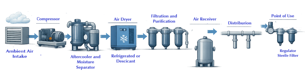
A GMP compressed-air system is a treatment and distribution train, not simply a compressor connected to piping. A typical architecture may include:
- Ambient intake positioned and protected to reduce ingestion of exhaust, solvent vapors, combustion products, dust, moisture, and other contaminants.
- Inlet filtration to protect the compressor from bulk particulate loading.
- Compressor stage or stages selected for capacity, turndown, lubricant strategy, discharge conditions, maintainability, and failure risk.
- Aftercooler and moisture separator to reduce discharge temperature and remove bulk condensed water.
- Wet receiver, where used, to buffer compressor operation and support bulk moisture separation.
- Coalescing and particulate prefiltration to protect the dryer and downstream treatment equipment.
- Dryer selected to deliver the required pressure dew point across defined loads and environmental conditions.
- Post-filters or adsorption stages to control desiccant dust, oil aerosol, oil vapor, odor, or other contaminants as required.
- Dry receiver, where used, to provide storage downstream of treatment and stabilize demand.
- Distribution header and branches designed to preserve pressure, dryness, cleanliness, and access for inspection or modification.
- Point-of-use regulation, filtration, monitoring, or sterile filtration selected for the specific application.
The exact order varies with compressor and dryer technology. The approved process and instrumentation diagram must show the actual configuration, normal and alternate flow paths, isolation valves, bypasses, drains, sample points, instruments, alarms, and connections to supporting utilities.
System Segregation and Shared Headers
A shared compressed-air plant can be appropriate when the central quality, capacity, reliability, and distribution controls satisfy all connected uses. Sharing can reduce equipment duplication and improve operating efficiency, but it can also extend the impact of a common failure across unrelated processes.
Separate generation, treatment, or distribution may be justified when:
- A use requires materially different dew point, oil, particle, or microbial control
- A breathing-air service cannot be adequately protected within the plant-air architecture
- Solvent, potent-compound, biological, or containment risks create a backflow concern
- Aseptic applications require a controlled terminal filtration and sterilization strategy
- Pressure or demand variation from one user can destabilize another critical user
- Maintenance or shutdown of the common system would create unacceptable production risk
- The common header contains legacy materials or contamination risks that cannot be adequately controlled
Segregation alone does not assure quality. A dedicated branch that is wet, corroded, poorly maintained, or inadequately filtered may present greater risk than a well-controlled shared system. The decision should be based on credible failure modes and the effectiveness of the complete control strategy.
System Boundary Definition
The system boundary should identify where responsibility transfers from the utility system to receiving equipment or the process. Boundaries commonly occur at a branch isolation valve, regulator, terminal filter, flexible hose connection, equipment connection, or valve manifold.
The boundary must not create an evidence gap. Utility ownership may end at an equipment connection, but the product-quality pathway continues through hoses, regulators, filters, check valves, manifolds, and equipment piping. Requirements should assign responsibility for maintenance, sterilization, filter integrity, replacement, sampling, and change control across the complete path.
Contamination Hazards and Control Strategy
Compressed-air quality is affected by contaminants entering with ambient air, generated during compression, introduced by treatment equipment, released from distribution materials, or transferred backward from connected processes. The control strategy should address the following hazard groups.
Solid Particles
Particles may enter through the intake or arise from compressor wear, pipe corrosion, desiccant attrition, filter-media damage, seal degradation, maintenance debris, or construction work. Particle control normally uses staged filtration so that each filter operates within its intended loading range and protects downstream equipment.
A high-efficiency terminal filter cannot compensate indefinitely for a contaminated or corroding distribution system. High upstream loading shortens terminal-filter life, increases differential pressure, and makes breakthrough or maintenance-related contamination more likely.
Water and Moisture
Ambient humidity becomes concentrated during compression. Cooling then causes water to condense. Separators, drains, dryers, and distribution design must prevent liquid water from remaining in the system.
Moisture can cause:
- Internal corrosion and particle generation
- Microbial survival or proliferation in wet locations
- Desiccant or filter degradation
- Instrument freezing or malfunction
- Product or surface contamination
- Blockage or damage at regulators and use points
The moisture specification should identify pressure dew point, the pressure at which it applies, and relevant operating conditions. Dew-point selection should consider the lowest credible pipe-surface temperature, seasonal conditions, expansion cooling, pressure reduction, and shutdown states. Specifying only “dry air” or an unexplained dryer rating is insufficient.
Oil and Hydrocarbons
Oil can occur as liquid, aerosol, or vapor. Potential sources include lubricated compressors, ambient intake contamination, compressor seals, downstream equipment, maintenance products, and process backflow.
An oil-free compressor reduces one important source but does not make the delivered air automatically oil free. Intake air can contain hydrocarbons, and treatment or distribution components can introduce contamination. The required total-oil control and test method must reflect the use. Where vapor control is important, coalescing filtration alone may be inadequate because it is primarily intended to remove liquid and aerosol rather than vapor.
Microorganisms
Compressed air is not inherently sterile. Dryness restricts microbial growth but does not prove absence of viable organisms. Organisms or spores can enter from intake air, persist in wet system locations, be introduced during maintenance, or move backward from a process connection.
Microbial requirements should be based on the exposure pathway and process risk. Non-contact instrument air may not require routine microbial testing. Air that directly contacts product or a critical surface may require a justified microbial limit and representative monitoring. Air entering an aseptic process or sterilized pathway generally requires a validated sterilizing-grade filtration strategy and controls that maintain filter integrity and dryness.
Gaseous Contaminants, Vapors, and Odor
Carbon monoxide, carbon dioxide, sulfur compounds, solvent vapors, cleaning-agent vapors, and other gaseous contaminants may enter through a poorly located intake or arise from compressor overheating or nearby activities. These contaminants may not be removed by particulate or coalescing filters.
The intake should be evaluated against nearby exhausts, vehicle traffic, boiler stacks, cooling towers, emergency-generator exhaust, solvent handling, roof work, and seasonal sources. The assessment should consider both normal operation and temporary conditions such as construction or portable equipment.
Backflow and Cross-Contamination
Connected process equipment can introduce liquid, vapor, microorganisms, powder, cleaning solution, or another gas into the compressed-air branch. Pressure reversal may occur during shutdown, vessel pressurization, cleaning, sterilization, or a control failure.
Backflow protection may include check valves, air gaps where technically feasible, automatic isolation, pressure monitoring, break tanks or intermediate barriers, dedicated branches, and operating sequences. A check valve should not be treated as an infallible contamination barrier without considering failure, fouling, inspection, and testability.
Applying ISO 8573 to GMP Compressed Air
ISO 8573-1:2010 provides a standardized system for expressing compressed-air purity classes for particles, water, and oil. It is a useful engineering and specification framework, but it is not a pharmaceutical GMP specification and does not assign one required class to every pharmaceutical application.
Assign Each Attribute Independently
An ISO 8573-1 designation uses separate classes for particle, water, and oil purity. The required class for one contaminant does not determine the other two. A specification should therefore define the required combination and the point in the system where it applies.
The selected classes should be derived from:
- Product and process sensitivity
- Direct or indirect contact pathway
- Aseptic or non-aseptic use
- Required equipment reliability
- Distribution temperature and condensation risk
- Compressor and treatment technology
- Downstream filtration or process controls
- Measurement capability and uncertainty
- Consequence of an excursion
Copying a commonly used three-number class into a user requirement without this assessment creates an appearance of precision without demonstrating fitness for use.
ISO Class 0 Claims
ISO 8573-1 includes Class 0 for particles, water, and oil. Class 0 is not a universal compressed-air specification and does not mean that a contaminant is absent. It represents a defined limit more stringent than Class 1 for the applicable contaminant.
Class 0 is encountered most often in supplier claims for oil-free compressors. Such a claim should identify the contaminant covered, numerical limit, test method, sampling location, and operating conditions. Certification at the compressor discharge does not demonstrate compliance throughout the distribution system or at GMP points of use.
For GMP applications, compressed-air specifications should be based on intended use and contamination risk. Particles, moisture, oil, microorganisms, and other relevant contaminants should be specified independently rather than relying on a general “Class 0 air” designation.
Define the Measurement Location and Condition
Purity can differ at the dryer outlet, receiver outlet, main header, remote branch, downstream of a regulator, and at the actual use point. The specification should state:
- Sampling or compliance location
- System pressure and demand condition
- Pressure dew point or atmospheric dew point, as applicable
- Whether the sample is upstream or downstream of terminal treatment
- Required stabilization or flushing
- Sampling equipment and materials
- Test method, detection capability, and uncertainty
- Treatment of intermittent or non-detect results
The corresponding ISO 8573 parts provide methods for measuring specific contaminants. Method selection must match the limit and contaminant form. For example, oil aerosol and oil vapor require different measurement considerations. ISO 8573-7:2003 provides a method for viable microbiological contaminant assessment, but ISO 8573-1 does not establish pharmaceutical microbiological acceptance limits.
Do Not Use ISO Classification as the Entire Specification
A GMP compressed-air specification may also need requirements for:
- Viable microorganisms
- Sterility or terminal-filter integrity
- Pressure and available flow
- Temperature
- Odor or specified gases
- Filter differential pressure
- Recovery after demand changes
- Alarm response
- Materials or cleanliness at the user interface
ISO classification should be one part of a use-specific requirement set rather than a substitute for process understanding.
Developing Use-Specific Air-Quality Specifications
One facility-wide specification may be appropriate when the complete system is designed and maintained to meet the most demanding connected use. It is not automatically required. Multiple specifications may be more technically justified when clearly segregated branches or terminal treatments serve materially different applications.
| Use category | Primary risk | Typical requirement focus | Additional considerations |
|---|---|---|---|
| Non-contact instrument air | Loss of control function; equipment damage | Pressure, flow, dew point, particles, oil protection | Fail position, reserve capacity, alarm response, barrier failure |
| Non-contact process air | Process interruption or environmental effect | Pressure, flow, dryness, particles, application-specific contaminants | Exhaust destination, room impact, cleaning status |
| Indirect-contact air | Deposition on a surface or component later exposed to product | Particles, oil, moisture, microbial risk as justified | Exposure duration, surface status, downstream cleaning or sterilization |
| Direct product-contact air | Transfer of contaminants to product | Particles, total oil, moisture, microorganisms, pressure and flow | Product sensitivity, dose or duration of exposure, downstream removal |
| Aseptic or post-sterilization air | Loss of sterile boundary | Appropriate upstream quality plus sterilizing-grade terminal filtration | Filter sterilization, integrity testing, dryness, backflow prevention |
| Breathing air | Personnel exposure | OSHA Grade D requirements and required source controls | CO alarm or monitoring, compressor location, incompatible connections |
Acceptance limits should be scientifically justified and practically measurable. A limit below the validated capability of the sampling and analytical method does not provide stronger control. The specification should also distinguish routine operating limits, alert or action criteria where used, and qualification acceptance criteria.
For product-contact applications, the assessment should evaluate the amount of air contacting the product, exposure duration, product moisture sensitivity, microbial susceptibility, route of administration, batch stage, downstream processing, and ability of later steps to remove or control introduced contamination.
For aseptic processing, FDA guidance states that compressed gas should have appropriate purity and that its microbiological and particle quality after filtration should be equal to or better than the environment into which it is introduced. FDA also recommends sterile membrane filters for specified operations involving sterile materials and integrity testing for filters serving as sterile boundaries or supplying sterile gases that can affect product.
Compressor Selection and Contamination Control
Compressor selection should consider the delivered-air requirement, not only nominal capacity or the label applied to the compression chamber.
Oil-Lubricated Compressors
Oil-lubricated compressors can provide reliable service when supported by effective separation, coalescing, adsorption where needed, monitoring, and maintenance. Their use requires explicit assessment of oil carryover, abnormal separator performance, lubricant suitability, and detection of deterioration.
Oil-Free Compressors
Dry-screw, water-injected, centrifugal, or other oil-free compression technologies reduce the risk of lubricant entering through the compression chamber. They do not eliminate ambient hydrocarbons, bearing or gearbox failure pathways, downstream contamination, or the need to control particles and water.
The term “oil-free” should be tied to the applicable compressor design standard or supplier claim and should not be converted into an unsupported claim about point-of-use air quality.
Compressor Controls and Sequencing
Multiple compressors should be sequenced to maintain pressure efficiently across the operating range. Control should avoid excessive cycling, prolonged unloaded operation, overheating, unstable pressure, or operation outside the efficient range. Lead-lag rotation, standby availability, permissives, alarms, and failure response should be defined.
The design should establish the acceptable operating state if one compressor is unavailable and identify whether production restrictions are required. A compressor marked “standby” does not provide redundancy if it lacks automatic or controlled transfer, adequate capacity, equivalent treatment, current maintenance, or routine exercise.
Drying, Filtration, and Condensate Management
Dryer Selection
Refrigerated, desiccant, membrane, and hybrid drying systems provide different dew-point capability, turndown behavior, energy demand, and failure modes.
Selection should consider:
- Required pressure dew point and seasonal minimum temperature
- Minimum and maximum flow
- Compressor discharge condition
- Pressure and temperature at the dryer inlet
- Regeneration method and purge demand
- Dew-point performance during switching or regeneration
- Desiccant attrition and downstream dust control
- Bypass arrangement and risk of untreated-air release
- Maintenance access and standby capability
- Recovery after shutdown or saturation
A dryer sized only for average flow may fail during peak demand or the worst seasonal inlet condition. A redundant dryer train may still share controls, prefilters, drains, or a common bypass that represents a single point of failure.
Filtration Strategy
Filters should be arranged according to contaminant load and downstream protection needs. A typical train may use a general-purpose particulate filter, coalescing stages, dryer-protection filters, adsorption for vapor control, and a downstream particulate filter to retain desiccant dust. Terminal filters may provide final particulate or sterile protection at selected use points.
Filter selection should define:
- Rated removal performance at actual pressure and flow
- Maximum allowable differential pressure
- Liquid-handling capability
- Materials of construction
- Compatibility with cleaning or sterilization methods
- Replacement or integrity-test criteria
- Housing drainage and orientation
- Bypass and isolation controls
Filter-change frequency should be based on supplier limitations, differential pressure, service conditions, risk, and performance history. Calendar replacement alone may be insufficient when load varies materially, while differential pressure alone may not detect media damage or loss of adsorption capacity.
Condensate Drains
Separators, filters, receivers, and low points depend on reliable drains. Failed-closed drains retain water and oil. Failed-open drains waste air, reduce capacity, and may draw contamination during shutdown or pressure cycling. Drain type, alarm capability, inspection, test frequency, discharge routing, and maintainability should be defined.
Condensate is a concentrated waste stream that may contain compressor lubricant and other contaminants. Its collection and disposal must prevent reconnection, aerosolization, overflow, or backflow into the air system.
Receivers, Distribution, and Point-of-Use Design
Air Receivers
Receivers stabilize pressure, buffer short demand peaks, reduce compressor cycling, and can support moisture separation. Their location relative to the dryer changes their function and contamination risk.
A wet receiver upstream of drying can promote bulk water separation but requires effective drainage and internal-condition control. A dry receiver downstream of treatment stores conditioned air but can become a contamination reservoir if internal corrosion, wetting, or maintenance contamination occurs. Inspection, pressure-vessel compliance, drains, relief devices, and internal condition should be addressed.
Distribution Materials and Configuration
Distribution materials should resist corrosion, minimize particle shedding, tolerate operating pressure and temperature, and remain compatible with the required air quality. Stainless steel, aluminum, suitable polymeric systems, copper, and coated carbon-steel systems may be appropriate in different applications. Material selection should be justified rather than based on a universal sanitary-piping rule.
The distribution design should address:
- Ring main versus branched architecture
- Pressure loss at peak and minimum demand
- Internal cleanliness during installation
- Sloping and drainage where condensation remains credible
- Low points and trapped sections
- Branch takeoff orientation
- Isolation for maintenance and expansion
- Flexible hoses and quick connections
- Cross-connection prevention
- Identification and flow direction
- Access to representative and worst-case sample points
- Future demand and controlled expansion
Compressed-air distribution is not a pharmaceutical-water loop, and water-system dead-leg rules should not be copied mechanically. Nevertheless, stagnant, wet, corroded, or inaccessible branches can create contamination risk. Unused branches should be removed or isolated under change control when they can no longer be maintained in a suitable state.
Point-of-Use Components
Point-of-use assemblies may include an isolation valve, regulator, pressure gauge or transmitter, filter, differential-pressure indication, check valve, sample connection, flow control, hose, and equipment connector. Each component can protect the process or create a new contamination and maintenance risk.
Regulators can generate particles or become wet during pressure reduction. Flexible hoses can shed material, retain moisture, be connected to the wrong service, or bypass a qualified terminal assembly. Quick-connect fittings should be keyed or otherwise controlled where connection to the wrong gas or air grade is credible.
Terminal filters should be installed where they can be inspected, replaced, sterilized, and integrity tested as required. The design should prevent condensate accumulation and process backflow. For aseptic uses, the relationship between the sterilizing-grade filter and the sterile boundary must be unambiguous.
Capacity, Demand, Turndown, and Redundancy
Compressed-air demand is dynamic. Design capacity should account for simultaneous users, equipment cycles, purge loads, dryer regeneration, leaks, future expansion, abnormal recovery demands, and the minimum pressure required at the most hydraulically disadvantaged critical use point.
The design basis should document:
- Connected and operating load
- Demand diversity and simultaneity assumptions
- Normal, peak, minimum, and upset demand
- Compressor and dryer turndown
- Receiver storage and allowable pressure decay
- Distribution pressure loss
- Critical-user minimum pressure and flow
- Recovery following a high-demand event
- Standby capacity and transfer time
- Production restrictions under degraded configurations
Redundancy should be evaluated by function. Multiple compressors do not assure a redundant utility if all compressors depend on one electrical feed, cooling-water source, controller, dryer, receiver, filter train, or distribution header. Likewise, dual dryers may not be redundant if a common valve lineup or control failure can bypass both.
A risk-based design may use N+1 equipment, a duty/standby train, stored reserve, controlled load shedding, production scheduling, or an approved alternate source. The selected approach should reflect the consequence and permissible duration of utility loss. Redundancy claims should be demonstrated under representative demand rather than inferred from equipment count.
Instrumentation, Automation, and Alarms
Instrumentation should provide the evidence needed to control the system and detect failure before unacceptable air reaches critical users. Depending on the design, critical measurements may include:
- Header and remote-point pressure
- Compressor discharge temperature
- Dryer inlet and outlet conditions
- Pressure dew point
- Filter differential pressure
- Receiver pressure
- Flow or demand
- Drain status
- Carbon monoxide for applicable breathing-air compressors
- Equipment status, permissives, and operating mode
Instrument location matters. A dew-point transmitter at the dryer outlet may confirm dryer performance but may not detect water introduced by a wet receiver, failed downstream drain, open bypass, or process backflow. A header-pressure transmitter may not represent the pressure at a remote critical user during peak demand.
Alarm strategy should distinguish equipment-protection alarms from GMP-relevant quality or availability alarms. Each critical alarm should have a defined setpoint basis, delay where justified, annunciation path, response procedure, record, and escalation rule. Alarm suppression, shelving, bypass, or setpoint change should be controlled.
Critical instruments should be included in the Calibration Program and Metrology Control. Calibration range, accuracy, location, environmental conditions, and access should support the actual operating and acceptance limits.
Automation should maintain an approved equipment lineup and identify abnormal states such as dryer bypass, standby unavailability, excessive dew point, low header pressure, drain failure, or loss of treatment. Where electronic data support release, excursion assessment, or continued-use decisions, data retention, access, time synchronization, backup, and review responsibilities should be defined.
Sampling and Testability by Design
The system should include sampling provisions that allow representative, safe, and repeatable collection without creating contamination or pressure hazards. Qualification and routine monitoring cannot compensate for sample points that condense moisture, shed particles, trap residue, or require uncontrolled hoses and adapters.
The sampling design should consider:
- Generator or treatment-train outlet
- Main distribution header
- Remote or hydraulically disadvantaged branches
- Highest-risk product-contact uses
- Branches downstream of pressure reduction
- Intermittent or low-use branches
- Locations upstream and downstream of terminal filters when diagnostic differentiation is needed
- Breathing-air sampling points where applicable
Sampling plans should distinguish system performance from terminal-treatment performance. A sample downstream of a point-of-use filter may demonstrate delivered quality for that user but conceal deterioration of the upstream distribution. Conversely, an upstream sample cannot demonstrate the condition of a terminal hose, regulator, or filter.
Sample trains should be compatible with the contaminant being measured. Tubing length, material, flow, pressure reduction, temperature, flushing, isokinetic considerations where relevant, microbial collection technique, and laboratory method can materially affect results. Requirements must be aligned with the selected ISO 8573 measurement method or the approved non-ISO method.
Maintenance and Intervention Risks
Compressed-air maintenance can directly change air quality and system availability. The Preventive Maintenance and System Reliability Strategy should address both equipment reliability and the contamination risks created by the work itself.
High-risk activities include:
- Compressor overhaul or lubricant change
- Separator, coalescer, adsorption cartridge, or terminal-filter replacement
- Dryer desiccant replacement
- Drain repair or replacement
- Receiver inspection or internal work
- Pipe cutting, branch addition, or valve replacement
- Opening a treated-air path to the environment
- Use of temporary compressors, dryers, hoses, or bypasses
- Control-logic or sequencing changes
- Extended shutdown followed by restart
Maintenance planning should specify isolation, cleanliness, approved materials, tool and debris control, protection of open ends, reinstatement checks, flushing or purging, leak testing, instrument status, filter verification, sampling, and release authority.
Lubricants, thread compounds, cleaning agents, gaskets, hoses, and replacement filter elements should be assessed for compatibility and contamination potential. “Equivalent” components should not be accepted solely on size or pressure rating when efficiency, media, adsorption capacity, shedding, extractables, sterilizability, or pressure drop can affect intended use.
Temporary Systems and Bypasses
Temporary equipment can introduce unfamiliar lubricants, ambient intake conditions, wet or contaminated hoses, inadequate dryers, missing alarms, or insufficient capacity. A temporary compressor should not be connected to a GMP header under a maintenance work order alone. It requires documented change and risk assessment, verified configuration, defined quality acceptance, connection cleanliness, backflow protection, monitoring, and release.
A bypass around a dryer or filter changes the qualified treatment path even if header pressure remains acceptable. Bypass valves should be locked, sealed, monitored, or otherwise controlled according to risk. Use of a bypass should trigger an assessment of affected time period, users, batches, and restoration testing.
Maintenance Performance Indicators
Recurring drain failures, rising filter differential pressure, increased compressor oil carryover, dew-point instability, desiccant dust, corrosion debris, leakage, excessive cycling, and repeat alarms are system-health signals. They should be trended and evaluated rather than closed as isolated work orders.
Changes, failures, temporary configurations, and return-to-service decisions should follow Utility System Change Control, Requalification, and Deficiencies.
Regulatory and Standards Framework
United States drug GMP regulations do not prescribe one universal compressed-air purity class. Applicable requirements arise from the use of suitable equipment, protection against contamination, cleaning and maintenance, written procedures, laboratory controls, investigations, and prevention of microbiological contamination where required.
Relevant provisions include:
- 21 CFR 211.63, requiring equipment of appropriate design, adequate size, and suitable location for intended use and cleaning and maintenance.
- 21 CFR 211.65, addressing equipment construction and contact surfaces so they do not alter product safety, identity, strength, quality, or purity.
- 21 CFR 211.67, requiring equipment and utensils to be cleaned, maintained, and, as appropriate, sanitized or sterilized at suitable intervals.
- 21 CFR 211.113, requiring written procedures to prevent objectionable microorganisms in nonsterile products and to prevent microbiological contamination of products represented as sterile.
- 21 CFR 211.160, requiring scientifically sound laboratory controls and appropriate specifications, standards, sampling plans, and test procedures.
For aseptic processing, FDA’s Sterile Drug Products Produced by Aseptic Processing—Current Good Manufacturing Practice specifically addresses purity, microbiological and particle quality, membrane filtration, dry gas filters, backflow prevention, and integrity testing of filters that serve sterile boundaries or supply sterile gases affecting product.
FDA’s Sterile Drug Process Inspections Compliance Program 7356.002A directs attention to process-gas generation, preventive maintenance, monitoring, sampling, sterilizing-grade filtration for gases used in aseptic operations or downstream of sterilization, and integrity testing of those filters.
OSHA’s 29 CFR 1910.134 establishes the controlling federal requirements for compressed breathing air supplied to respirators. These personnel-safety requirements should remain distinct from pharmaceutical product-contact specifications.
The Risk-Based Validation Approach for GMP Systems provides the broader basis for aligning design, qualification, and lifecycle effort with intended use, credible failure modes, control effectiveness, and product-quality consequence.
Design and Qualification Evidence
Design documentation should establish a traceable basis for the installed system and later qualification. Expected evidence may include:
- Approved use-point inventory and impact classification
- User requirements and air-quality specifications
- Design basis and capacity calculations
- Contaminant-control strategy
- Intake-location assessment
- Compressor, dryer, receiver, and filter selection records
- Process flow diagrams and process and instrumentation diagrams
- Distribution drawings and critical-use-point schedule
- Materials and component specifications
- Control narrative, alarm list, and failure positions
- Redundancy and common-mode failure assessment
- Sampling and monitoring strategy
- Maintenance and consumable requirements
- Breathing-air boundary and OSHA compliance strategy, where applicable
- Supplier documentation and acceptance criteria
- Commissioning and qualification plan
Qualification should verify the actual installed configuration, critical instruments, controls, alarms, capacity, recovery, distribution performance, air-quality attributes, representative use points, and terminal controls. Testing should cover approved operating ranges and relevant demand conditions rather than relying only on an unloaded sample at the compressor room.
Initial qualification does not establish indefinite control. Routine monitoring, maintenance, calibration, deviations, changes, periodic review, and requalification must preserve the approved state. The detailed lifecycle framework is addressed in Utility System Lifecycle, Monitoring, and Risk-Based Control.
Common Design and Control Weaknesses
Common weaknesses include:
- Treating every use point as the same category without an inventory or contact-pathway assessment
- Calling all pneumatic service “instrument air” even where it contacts product or cleaned surfaces
- Using plant air for breathing without demonstrating OSHA compliance
- Selecting an ISO 8573 class from convention rather than intended use
- Interpreting Class 0 as zero contamination
- Specifying “oil free” without defining total-oil limits, measurement method, and sampling location
- Stating a dew point without identifying pressure or operating condition
- Ignoring microbial risk because the air is dry
- Relying on terminal filters while the distribution system remains wet or corroded
- Locating the ambient intake near exhaust, traffic, or solvent sources
- Installing bypasses that can deliver untreated air without alarm or control
- Claiming redundancy based only on equipment count
- Omitting demand diversity, recovery, or remote-user pressure from capacity calculations
- Failing to evaluate backflow from connected process equipment
- Installing sample points that cannot produce representative or repeatable samples
- Treating hoses, regulators, quick connects, and terminal filters as outside the controlled boundary
- Returning the system to use after invasive maintenance without defined verification
- Connecting temporary compressors or hoses without change control and air-quality acceptance
- Failing to trend drain, dryer, filter, dew-point, oil, pressure, and reliability signals together
These weaknesses are normally interconnected. For example, an undersized dryer may produce elevated dew point only during peak demand; a failed drain may then wet a receiver; internal corrosion may increase particles; and a terminal filter may load rapidly without revealing the upstream cause. Effective design and lifecycle control must evaluate the complete failure pathway.
Summary
A GMP compressed-air system must be designed from its approved uses and credible failure pathways. Instrument air, process air, product-contact air, and breathing air require different evaluations, and the categories may overlap. No single compressor label, dryer rating, ISO class, or point-of-use filter demonstrates that the delivered air is fit for every application.
The control strategy should integrate intake protection, compression, cooling, moisture separation, drying, staged filtration, storage, distribution, point-of-use treatment, backflow prevention, capacity, redundancy, instrumentation, alarms, sampling, maintenance, and controlled return to service. ISO 8573 provides a valuable framework for particles, water, oil, and contaminant measurement, but GMP specifications must remain use-specific and must add microbial, sterile-boundary, functional, or safety requirements where applicable.
When requirements, architecture, contamination controls, operating limits, and maintenance risks are defined before qualification, the installed system can be tested against a coherent design basis and maintained through a defensible lifecycle.