

Steam-in-Place (SIP) Utility Systems
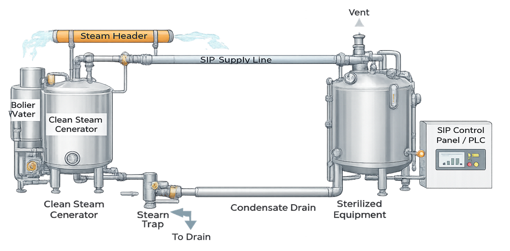
Steam-in-place (SIP) is an integrated moist-heat sterilization process used to sterilize the internal product-contact surfaces of vessels, piping, filters, transfer paths, filling equipment, and associated components without dismantling the sterilized boundary. Clean steam supplies the sterilizing medium, but successful SIP depends on more than steam availability. Equipment geometry, air removal, condensate drainage, heat transfer, cycle control, sterile-boundary integrity, and the condition of the system before and after the cycle all affect the result.
The GMP significance of SIP depends on intended use. Where an SIP cycle establishes the sterile state of equipment used for aseptic processing or sterile product manufacture, failure can directly compromise sterility assurance. In nonsterile biotechnology or pharmaceutical operations, SIP may instead establish a defined microbial-control state needed to protect a culture, intermediate, or subsequent process. The required evidence should therefore reflect the sterilization objective and the consequence of failure rather than treating every steam-connected system identically.
SIP should be managed as one validated process spanning the clean-steam source, the installed equipment path, the control recipe, the sterilized boundary, and the receiving manufacturing operation. Qualification of individual components is necessary, but it does not replace demonstration that the complete configured path can be sterilized reproducibly under defined worst-case conditions.
SIP Scope and System Boundaries
An SIP boundary is the complete internal surface and component path intended to be rendered sterile or brought to a defined microbial-control state by one approved cycle. Depending on the application, the boundary may include:
- Process vessels and vessel heads
- Agitator shafts, seals, and nozzles
- Product-transfer and recirculation piping
- Addition, sampling, inoculation, and harvest lines
- Spargers and dip tubes
- Instrument branches and thermowells
- Vent paths and sterile vent filters
- Process filters and filter housings
- Valves, valve blocks, diaphragms, and seats
- Pumps or other components qualified for in-place sterilization
- Drain paths, steam traps, and condensate discharge connections
- Connections to filling, formulation, or hold equipment
The boundary should be shown on approved piping and instrumentation diagrams and, where the operating route changes, supported by route or valve-state documentation. Boundary definitions should identify steam-entry points, air-removal and vent points, condensate exits, normal and exceptional flow paths, required valve positions, excluded branches, sterile-side interfaces, and the point at which the sterilized state is established.
System boundaries are especially important when one steam header serves multiple equipment trains or when recipe-controlled valve matrices create different sterilization circuits. A successful cycle on one route cannot be assumed to cover another route with different length, elevation, volume, geometry, valve configuration, or condensate behavior.
The associated Clean-in-Place (CIP) Utility Systems article explains the separate cleaning function that normally precedes SIP. CIP removes residues and prepares surfaces for sterilization; SIP applies a validated moist-heat process. Neither activity substitutes for the other.
SIP Is a Process, Not Merely a Utility
The term “SIP utility system” is convenient for navigation, but the validated object is broader than a utility skid. A meaningful SIP assessment includes:
- The clean-steam supply and its capacity at the required demand
- Steam distribution between the source and equipment
- Equipment and piping hygienic design
- Air-displacement or evacuation capability
- Condensate collection and removal
- Heat-up, exposure, and controlled completion logic
- Measurement and recording systems
- The recipe and approved configuration
- Sterilized-boundary closure and post-cycle protection
- The manufacturing operation that relies on the cycle
This distinction prevents an overly narrow qualification program that verifies only steam pressure, valves, and control-panel functions while leaving sterilization performance insufficiently demonstrated.
Relationship to Clean Steam
Clean steam is commonly used for SIP because condensate can contact product-contact surfaces and because steam-borne contaminants may remain after condensation. The required steam specification should be based on intended use, equipment compatibility, condensate risk, and the sterilization process rather than on an undefined label such as “pure steam.”
The Clean Steam Systems for GMP Applications article addresses intended use and the distinction between clean steam and plant steam. The Clean Steam System Design and Quality Attributes article covers generation, distribution, drainage, non-condensable gases, dryness, superheat, condensate quality, capacity, and representative sampling.
Clean-steam suitability and SIP performance are related but distinct:
| Evidence | What it demonstrates | What it does not demonstrate |
|---|---|---|
| Source and condensate quality | Steam and condensate meet approved quality requirements at represented locations | Complete sterilization of an equipment path |
| Steam-quality testing | Defined physical attributes are suitable for the intended sterilization application | Adequate air removal or heat penetration in every SIP circuit |
| Utility capacity testing | The supply can support specified demand and recovery conditions | Acceptable temperature distribution inside connected equipment |
| SIP cycle validation | The configured system achieves the required exposure and lethality at worst-case locations | Continued suitability of every clean-steam use point unless included in the study |
The Clean Steam System Qualification, Monitoring, and Requalification article addresses qualification and lifecycle evidence for the supporting steam utility. SIP validation should use that evidence but should also test the installed sterilization path under the operating conditions that govern air removal, condensate behavior, heat transfer, and microbial lethality.
Supply pressure alone is not evidence of saturated-steam conditions at the cold spot. Pressure and temperature may be correlated for saturated steam, but trapped air, non-condensable gases, excessive superheat, condensate accumulation, heat loss, measurement error, or a closed path can invalidate a simple pressure-based inference.
Architecture and Major Components
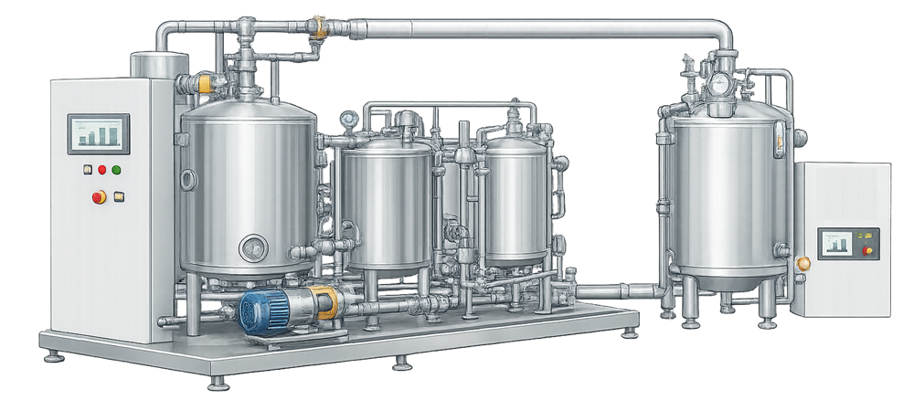
SIP arrangements vary from a simple clean-steam connection to highly automated multi-route systems. Common architectures include:
Dedicated Equipment SIP
A vessel or process unit has dedicated steam-entry, vent, drain, measurement, and control provisions. This can simplify boundary definition and recipe control, but connected branches, instruments, seals, spargers, and transfer paths still require explicit coverage.
Central Steam Supply with Local Cycle Control
A common clean-steam distribution system supplies several pieces of equipment. Each equipment train has local valve sequencing, monitoring, and cycle logic. Shared steam capacity, concurrent-cycle restrictions, source interruptions, and common-mode failures become important qualification considerations.
Recipe-Selected Routing
Automated valves establish different SIP paths from a common header. Route verification, valve-state proof, configuration control, and protection against simultaneous incompatible routes are critical. Each materially different route should be evaluated rather than represented solely by the shortest or most convenient circuit.
Integrated CIP/SIP Skid
The same automation platform may control cleaning and sterilization phases. Shared tanks, pumps, valves, instruments, and return paths can introduce cross-phase risks. The system should prevent cleaning chemical, rinse water, recovery solution, or nonsterile utility paths from entering the sterilized boundary during or after SIP.
Major Functional Elements
A typical SIP system may include:
- Qualified clean-steam source and distribution header
- Pressure-reducing and control valves
- Steam separators where justified
- Supply isolation and route-selection valves
- Steam traps and condensate collection
- High-point vents and low-point drains
- Sterile vent filters and filter housings
- Temperature and pressure instruments
- Independent validation sensors during studies
- Flow, conductivity, or condensate detection where applicable
- PLC, distributed control system, or skid controller
- Human-machine interface and recipe management
- Historian, batch-report, or electronic-record functions
- Alarm, interlock, and permissive logic
- Utility-failure and emergency-shutdown functions
Component lists alone do not define performance. The important question is how components act together throughout conditioning, exposure, completion, depressurization, drying where applicable, and sterile hold.
Hygienic Design and Sterilizability
Equipment can be cleanable without being reliably sterilizable. SIP design review should therefore consider both pre-sterilization cleanliness and the ability to displace air, contact all required surfaces with steam, remove condensate, and maintain the sterile boundary afterward.
Drainability
Condensate forms continuously as steam heats colder metal and loses energy. The system should direct condensate toward effective removal points without pooling in low spots, valve bodies, instrument branches, housings, spargers, hoses, or transfer lines. Design review should address:
- Pipe slope in the operating orientation
- Low-point drain location
- Steam-trap type, orientation, capacity, and discharge conditions
- Potential backpressure in common condensate lines
- Valve-body and diaphragm-pocket drainage
- Vessel-nozzle and dip-tube geometry
- Insulation and local heat-loss conditions
- Temporary connections and flexible assemblies
- Installation tolerances that can defeat nominal drawing slopes
A low point shown as drained on a drawing may still retain condensate because of field-installed slope, support settlement, trap malfunction, blocked discharge, or differential pressure across the drain path. Installation walkdowns and thermal studies should confirm actual behavior.
Venting and Air Removal
Air is a major obstacle to saturated-steam sterilization. Steam must reach surfaces and condense to transfer latent heat effectively. Air pockets can produce locations where indicated pressure appears adequate but the local temperature or lethality is insufficient.
Air-removal provisions may include gravity displacement, controlled steam flushing, pulsed steam, vacuum-assisted evacuation, dedicated vents, or combinations appropriate to the system. Validation should demonstrate that the selected method works for the actual geometry and configuration. Vent locations should not be chosen only for convenience; they should support removal from credible high points, remote branches, dead-ended legs, and enclosed volumes.
Sterilization of Difficult Features
Particular attention should be given to:
- Long or narrow branches
- Small-bore sample lines
- Spargers with many small openings
- Hydrophobic vent-filter housings
- Diaphragm-valve cavities
- Instrument impulse lines
- Pump seals and rotating assemblies
- Double-seat or mixproof valves
- Transfer-panel and valve-matrix paths
- Points with poor insulation or high heat loss
- Low points where condensate can accumulate
- Interfaces temporarily opened after SIP
The FDA inspection guide for sterile drug-substance manufacturers specifically identifies SIP cold spots, condensate accumulation, steam injection and discharge points, and maintenance-related failures as areas requiring attention. FDA, Sterile Drug Substance Manufacturers inspection guide
Materials, Seals, and Repeated-Cycle Effects
Materials should tolerate repeated exposure to temperature, pressure, moisture, and any preceding cleaning chemicals. Gaskets, diaphragms, valve seats, lubricants, filter elements, sensor seals, sight glasses, hoses, and polymeric components can age or deform under repeated cycling. Maintenance strategy should address failure modes such as:
- Seal compression loss or extrusion
- Diaphragm fatigue
- Stress cracking
- Filter wetting or loss of hydrophobicity
- Corrosion or surface damage
- Insulation degradation
- Trap fouling or failure
- Sensor drift
- Valve leakage across a sterile boundary
Component compatibility should be supported by supplier data and actual operating conditions, including cycle frequency and maximum exposure—not merely nominal sterilization temperature.
Sterile-Boundary Definition and Protection
SIP effectiveness is not complete when the exposure phase ends. The system must remain protected until its intended use is complete or until another controlled sterilization cycle is performed.
The approved sterile-boundary definition should identify:
- Every surface intended to be sterilized
- Boundary valves and closed interfaces
- Sterile vents and gas overlays
- Post-cycle pressure state
- Permitted manipulations and connections
- Hold conditions and maximum sterile-hold time
- Required leak or integrity checks
- Actions after alarm, pressure loss, opening, or maintenance
- Criteria for declaring the boundary no longer sterile
For aseptic operations, FDA guidance expects the entire sterile-processing path to be sterilized and protected. Materials that can withstand heat sterilization, including SIP, should be sterilized by that method where appropriate. FDA Guidance for Industry: Sterile Drug Products Produced by Aseptic Processing
Post-Cycle Pressure and Sterile Gas
Some systems maintain positive pressure after SIP using sterile-filtered air or nitrogen. The gas source, final filter, filter housing, condensate exposure, valve sequencing, pressure control, and loss-of-pressure response become part of the sterile-boundary control strategy. A gas overlay cannot be treated as an unrelated utility when its failure can permit contamination of the sterilized equipment.
Sterile Hold Time
The interval between cycle completion and use should be defined and justified. The hold-time study should represent the actual boundary, pressure regime, vent-filter condition, permitted interventions, environmental exposure, and worst-case duration. A maximum hold time should not be established solely from historical convenience or from one unrelated equipment train.
Connections and Interventions
Post-SIP connections can invalidate the sterilized state unless they are performed through a validated aseptic connection, a sterilizable connection sequence, or another justified control. Procedures should define the status of capped branches, temporary hoses, sample ports, transfer panels, and maintenance access points.
Critical Process Parameters and Supporting Variables
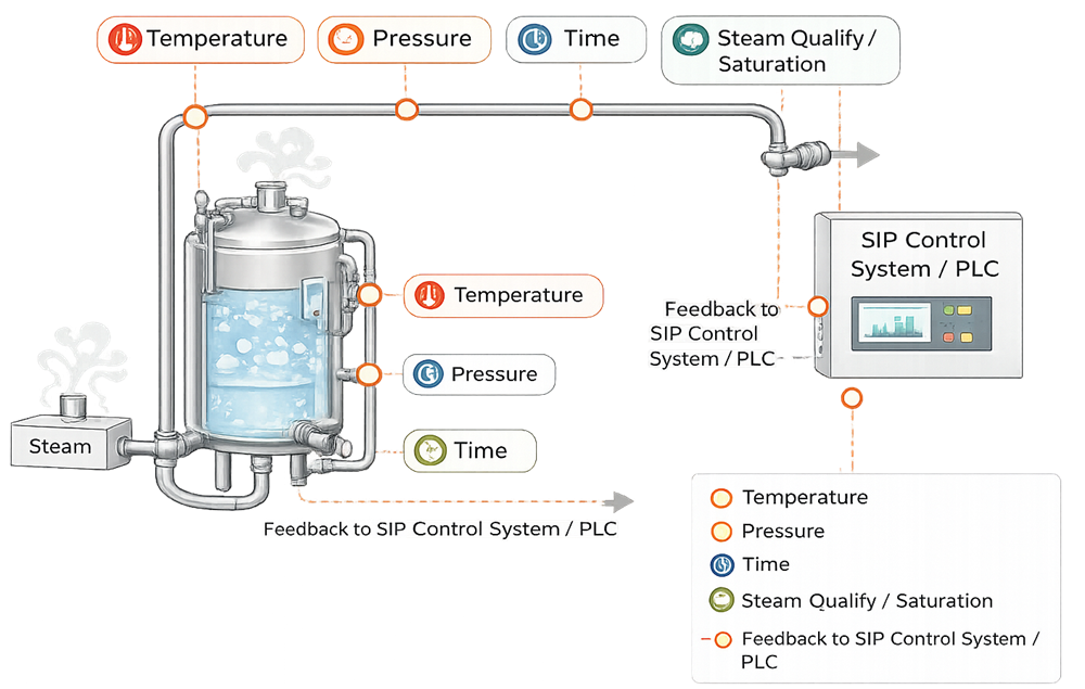
SIP cycles are commonly characterized by temperature, time, and pressure, but those values are meaningful only when interpreted with steam condition, air removal, drainage, load or configuration, and measurement location.
Temperature
Temperature is measured at locations selected to demonstrate heat distribution and exposure. The control sensor may regulate the cycle, while independent validation sensors determine whether all required locations meet acceptance criteria. A controller reading does not automatically represent the cold spot.
Exposure Time
Exposure time should begin only after defined conditions are achieved at the locations required by the cycle logic. Starting the timer when steam enters the system or when one control sensor reaches setpoint can overstate effective exposure elsewhere.
Pressure
Pressure supports process control, steam-flow establishment, condensate discharge, and evaluation of steam conditions. The pressure-temperature relationship can help identify abnormal steam conditions, but pressure is not a substitute for distributed temperature evidence.
Steam Quality and Saturation
Steam dryness, non-condensable gases, superheat, distribution heat loss, and source stability can influence heat transfer. The necessary tests and limits should be based on the intended application and justified sampling locations. A good result near the generator does not prove identical behavior at a remote SIP user during peak demand.
Air-Removal Conditions
Relevant variables may include purge duration, vacuum depth, number and sequence of pulses, vent-valve position, vent temperature, steam-flow condition, and route configuration. Acceptance should be tied to demonstrated heat distribution and sterilization performance, not only to completion of programmed steps.
Condensate-Removal Conditions
Trap function, drain temperature, differential pressure, discharge backpressure, drain-valve sequencing, and evidence of condensate clearance may be critical. The cycle should respond appropriately when drainage is inadequate.
Configuration and Load
The SIP configuration includes valve positions, installed components, filter housings, hoses, equipment fill state where applicable, agitator operation, and connected branches. Configuration errors can change the heat-transfer and drainage challenge even when nominal recipe parameters remain unchanged.
Cycle Development
Cycle development establishes how the installed system will be conditioned, exposed, completed, and protected. It should precede formal performance qualification and should generate the technical basis for recipe steps, limits, alarm responses, study locations, biological challenges, and routine acceptance criteria.
Define the Sterilization Objective
The objective may be:
- Sterilization of an aseptic-processing path
- Sterilization of a vessel before sterile compounding or holding
- Sterilization of a bioreactor and connected additions or harvest paths
- Microbial control of equipment used for a nonsterile but contamination-sensitive process
- Sterilization of a filter housing and associated piping
The objective determines the required assurance, microbial rationale, cycle-development approach, and evidence. The Moist Heat Sterilization Principles article explains saturated-steam lethality, resistance, thermal exposure, and common validation approaches.
Establish the Initial Cycle Sequence
A typical cycle can include:
- Pre-cycle readiness and route confirmation
- Drain and vent alignment
- Air-removal or steam-flush conditioning
- Controlled heat-up
- Exposure initiation after acceptance conditions are met
- Exposure at defined parameters
- Controlled completion and steam isolation
- Condensate removal or drying where required
- Sterile-gas admission and positive-pressure hold where applicable
- Cycle review and release of the sterilized boundary
The sequence should be tailored to the equipment. A vessel with a sparger, vent filter, and several transfer lines may require different timing and valve actions from a short product-transfer path.
Engineering Studies
Development work may use temporary sensors, thermal imaging where useful, condensate observation, drain-temperature measurements, valve-timing studies, steam-quality data, and repeated trials. The goal is to understand where air or condensate remains, how quickly sections heat, which point is slowest, and how supply or configuration changes affect performance.
Development failures are evidence, not noise. Cold locations, inconsistent heating, slow vents, or trap limitations should lead to design or recipe correction before formal qualification rather than being concealed by longer exposure without understanding the cause.
Identify Worst-Case Conditions
Worst-case selection should be supported by engineering evidence. Relevant factors include:
- Longest and largest-volume path
- Lowest steam pressure at the user
- Greatest simultaneous steam demand
- Highest heat loss
- Most remote or poorly insulated branch
- Most difficult air-removal geometry
- Lowest or most complex drain path
- Largest filter housing or most restrictive vent
- Maximum approved equipment configuration
- Minimum and maximum permitted process fill where applicable
- Components with high thermal mass
- Slowest validated heat-up condition
- Minimum permitted exposure setpoint
No single path necessarily represents all failure modes. A remote line may be worst for supply pressure, while a low sparger may be worst for condensate and a vent-filter housing may be worst for air removal.
Define Acceptance Criteria Before Qualification
Acceptance criteria should address, as applicable:
- Correct route and component configuration
- Successful air-removal sequence
- Required temperature at specified locations
- Exposure duration and start logic
- Minimum delivered lethality or other cycle criterion
- Pressure and temperature consistency where used
- Condensate drainage and absence of unacceptable pooling
- Biological-indicator results and control validity
- Alarm and interlock performance
- Complete, attributable cycle records
- Post-cycle pressure and sterile-boundary status
- Repeatability across required runs
Acceptance criteria should not be rewritten after an unexpected result merely to fit observed performance. Deviations should be investigated and the effect on cycle validity assessed.
Automation, Recipes, and Electronic Records
Automated SIP systems often perform GMP-significant functions: route selection, permissive checks, valve sequencing, timer initiation, exposure control, alarm handling, cycle termination, data recording, and batch-report generation. The system should be assessed and validated in proportion to those functions.
Recipe Definition and Control
An approved recipe should identify:
- Applicable equipment and route
- Required preconditions
- Valve states and sequence
- Air-removal parameters
- Heat-up criteria
- Exposure setpoints and allowable ranges
- Timer-start and reset logic
- Completion conditions
- Post-cycle pressure or gas-overlay steps
- Alarm responses and abort conditions
- Authorized parameter ranges
Recipe names alone are insufficient configuration control. The approved baseline should include parameter values, step logic, software or configuration version, associated equipment boundary, and authorization status.
Permissives and Interlocks
Examples include confirmation that:
- The CIP cycle is complete and the route is appropriately drained
- Correct equipment is selected
- Incompatible routes are isolated
- Drain and vent paths are available
- Required instruments are healthy and calibrated
- Steam supply conditions are adequate
- Product or nonsterile material cannot enter the boundary
- Exposure cannot begin prematurely
- The cycle aborts or holds safely after critical failure
Alarm and Failure Handling
The system should distinguish conditions that merely notify an operator from those that invalidate or interrupt the sterilization cycle. Critical events can include low temperature, insufficient exposure, loss of steam pressure, drain failure, valve-position disagreement, sensor fault, PLC or communication failure, loss of sterile-gas pressure, and unauthorized intervention.
The recipe should define whether recovery is permitted, whether exposure time resets, and when a complete restart is required. Operators should not be expected to improvise recovery logic during a failed sterilization cycle.
Data Integrity and Cycle Records
Records supporting cycle release should be complete, attributable, contemporaneous, original or appropriately retained, and accurate. The design should address:
- User access and role assignment
- Recipe and setpoint authorization
- Audit trails for GMP-relevant changes
- Time synchronization
- Sensor identification
- Raw data and calculated values
- Alarm and event chronology
- Aborted or incomplete cycles
- Report-generation logic
- Backup, restoration, and record retention
- Review of manual entries and overrides
A printed summary that omits alarms, temporary sensor failures, bypasses, or operator interventions may not support an adequate release decision.
Qualification and Validation Strategy
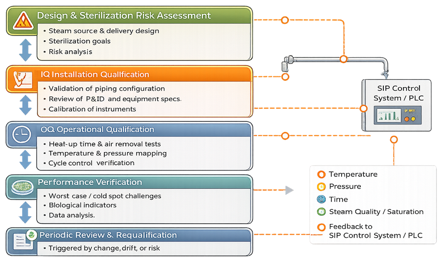
The Steam Sterilization Qualification Lifecycle article provides the broader relationship among requirements, design, qualification, process performance, routine control, and requalification. For SIP, the strategy should integrate equipment qualification with sterilization-process validation while preserving the purpose of each activity.
Requirements and Design Review
Requirements should define the sterilized boundary, intended use, sterilization objective, cycle family, steam interface, capacity, operating configurations, control functions, data needs, post-cycle protection, maintenance access, and expected lifecycle evidence. The general URS for GMP Facilities, Utilities, and Equipment framework can be applied to SIP equipment and its automation.
Design qualification or an equivalent documented review should evaluate:
- Compatibility between clean-steam supply and peak SIP demand
- Boundary completeness
- Hygienic design and materials
- Slope, drainage, and trap arrangement
- Venting and air removal
- Instrument locations and calibration access
- Valve leakage and cross-connection risks
- Sterile-filter and sterile-gas interfaces
- Automation architecture and failure response
- Sampling and validation-sensor access
- Maintainability without compromising hygienic design
- Post-cycle sterile-hold strategy
Installation Qualification
Installation qualification should verify the approved installed state, including:
- Equipment and component identification
- Piping and instrumentation diagrams
- Materials and surface-finish records where applicable
- Weld and passivation documentation
- Pipe slope and drain orientation
- Valve, trap, vent, and filter installation
- Instrument ranges, accuracy, calibration, and location
- Utility and electrical connections
- Automation hardware and software versions
- As-built route and boundary verification
- Drawings, manuals, spare parts, and maintenance information
- Resolution or control of punch-list items
The Installation Qualification (IQ) article provides the general installed-state evidence model. For SIP, field verification of drainability and actual route geometry is especially important because a drawing alone cannot establish thermal performance.
Functional and Operational Qualification
Operational qualification should demonstrate that the installed system operates throughout approved ranges and responds correctly to normal, challenge, and failure conditions. Typical testing includes:
- Route and valve-sequence verification
- Recipe selection and version control
- Permissive and interlock challenges
- Air-removal sequence execution
- Heat-up and exposure control
- Timer-start, hold, reset, and completion logic
- Pressure and temperature control
- Vent and drain functions
- Alarm annunciation, acknowledgment, and recording
- Sensor-failure response
- Utility interruption and recovery
- Power-loss and controller-restart behavior
- Manual mode, override, and bypass controls
- Electronic records, reports, audit trails, and backup
- Concurrent demand and source-capacity conditions
The Operational Qualification (OQ) article explains functional challenge principles. SIP OQ should test the logic that protects the sterilization process, but successful OQ does not by itself establish delivered lethality at all worst-case locations.
Physical Performance Qualification
Physical studies should demonstrate heat distribution and penetration throughout the defined boundary. Independent calibrated sensors should be placed using development data and engineering rationale, with emphasis on cold spots and difficult features.
Studies commonly evaluate:
- Heat-up profiles
- Temperature distribution
- Cold-spot repeatability
- Exposure duration at required locations
- Delivered lethality, such as accumulated F0 where scientifically appropriate
- Pressure-temperature relationship
- Air-removal effectiveness
- Condensate drainage
- Cycle-to-cycle variability
- Minimum and maximum approved operating conditions
- Representative and worst-case routes
F0 is a calculated equivalent exposure referenced to a defined temperature and z-value. It can integrate varying temperatures into one lethality measure, but it should not obscure inadequate air removal, poor drainage, or a location that never reaches an appropriate moist-heat condition. The calculation method, sensor data, start and stop rules, and acceptance basis should be predefined.
Biological Qualification
Biological indicators (BIs) can provide direct microbial-resistance challenges at identified worst-case locations. Selection should consider the organism, resistance characteristics, population, carrier, packaging or placement, recovery method, and suitability for moist heat. The Biological Indicators article addresses BI selection, resistance, controls, placement, incubation, and interpretation.
BI placement should be technically justified and should not create an artificial condition unrelated to the actual system unless that challenge is intentional and understood. Placement only at easily accessible drains or near the control sensor can miss more difficult locations. Positive controls, transport controls where needed, incubation conditions, growth-promotion suitability, and chain of custody should be defined.
Biological evidence should be interpreted with the physical cycle data. A passing BI result does not excuse a failed physical acceptance criterion, and acceptable temperatures do not automatically resolve an unexplained BI positive.
Sterility Assurance and Validation Approach
The validation approach may be overkill, bioburden-based, or another scientifically justified moist-heat strategy. The target lethality and microbial challenge should reflect the process, equipment use, expected bioburden, and required assurance. The Sterility Assurance Level Concepts article explains the probabilistic meaning of sterility assurance level and why it should not be reduced to a single BI observation.
For sterile drug products, 21 CFR 211.113(b) requires validation of aseptic and sterilization processes. 21 CFR 211.113 Equipment must also be cleaned, maintained, and sterilized as appropriate under written procedures. 21 CFR 211.67
Number and Selection of Qualification Runs
The number of runs should be sufficient to demonstrate reproducibility across the selected conditions and configurations. A fixed number should not substitute for a protocol rationale. Factors include:
- Number of materially different routes or equipment configurations
- Variability observed during development
- Complexity of air removal and drainage
- Steam-supply variability
- Cycle-control strategy
- Consequence of failure
- Use of bracketing or matrixing
- Prior knowledge from equivalent systems
- Planned routine monitoring
Where bracketing or matrixing is used, the represented configurations and limits of the conclusion should be explicit. The longest line is not automatically worst for every attribute.
Release of the Validated SIP Process
Release should occur only after approved review confirms that:
- The sterilized boundary and intended use are defined
- Required design and installation evidence is accepted
- Instruments and automation are qualified
- Critical deviations are resolved or formally assessed
- Physical and biological studies meet acceptance criteria
- Routine recipe parameters and alarm limits are approved
- Cycle-review and release procedures are available
- Operators, maintenance personnel, and reviewers are trained
- Sterile-hold and post-cycle protection controls are established
- Requalification triggers and ownership are defined
The release decision should identify the approved recipes, equipment trains, routes, operating ranges, configurations, hold times, and any limitations. “SIP system qualified” is too broad if only selected circuits or configurations were studied.
Routine Cycle Control and Release
Routine operation relies on the validated relationship between monitored parameters and sterilization performance. Each cycle record should be reviewed against approved criteria before the sterilized boundary is used, unless an appropriately validated automated release approach has been established.
Routine evidence can include:
- Correct equipment and recipe identification
- Approved recipe version
- Pre-cycle status and route confirmation
- Air-removal phase completion
- Required temperature and pressure profiles
- Exposure time and completion status
- Critical alarms, holds, overrides, and interventions
- Drain or vent evidence where monitored
- Post-cycle pressure or sterile-gas status
- Reviewer decision and boundary release
The routine control sensor should have a demonstrated relationship to the qualified cold spots. If maintenance, configuration, or operational evidence suggests that relationship has changed, continued reliance on the original mapping should be reassessed.
Failed, Aborted, or Interrupted Cycles
A cycle should not be accepted merely because the displayed exposure timer ultimately reached its target. The assessment should consider when the interruption occurred, which locations had reached conditions, whether air or condensate could have re-entered, how the recipe handled time accumulation, and whether the validated state remained represented.
Procedures should define:
- Events requiring cycle abort
- Permitted automatic recovery
- Conditions requiring timer reset
- Conditions requiring a complete restart
- Product or equipment status during investigation
- Data required for quality-unit disposition
- Controls preventing use of an unreleased boundary
Manual addition of time after a deviation should not be accepted without a scientifically justified assessment of the entire exposure history and the physical state of the system.
Continued-Use Decisions
When an alarm, excursion, or data gap occurs, the assessment should address both immediate cycle validity and potential broader loss of control. Evidence may support rejection of one cycle, targeted verification, temporary restrictions, maintenance, requalification, or suspension of the affected equipment.
Maintenance and Return to Service
SIP systems can fail through gradual deterioration as well as obvious breakdown. Preventive and condition-based maintenance should focus on components whose failure can affect steam delivery, drainage, measurement, route integrity, or sterile-boundary protection.
Relevant work includes:
- Steam-trap inspection or performance testing
- Valve and diaphragm maintenance
- Gasket and seal replacement
- Vent-filter replacement and integrity testing
- Instrument calibration
- Drain and condensate-line inspection
- Insulation repair
- Control-valve tuning
- Software, controller, and communication maintenance
- Backup verification
- Inspection for corrosion, rouging, leakage, or weld damage
Post-maintenance verification should be selected from the failure modes introduced by the work. Replacing a like-for-like pressure gauge may require calibration and functional confirmation; opening a sterile boundary, replacing a trap, changing a valve body, modifying a drain, or repairing insulation near a cold spot can require more extensive functional or thermal verification.
Maintenance records should identify the affected boundary, component, work performed, parts used, as-left condition, calibration status, required testing, and authorization for return to service. A work-order closure alone does not establish that the SIP process remains validated.
Change Control
Changes should be assessed against both installed-system qualification and sterilization-cycle validation. Examples include:
- New equipment, routes, branches, or use points
- Valve, trap, drain, vent, or piping changes
- Instrument replacement or relocation
- Recipe, timer, setpoint, or tolerance changes
- Automation software or configuration changes
- Clean-steam source or distribution changes
- Increased concurrent steam demand
- Filter, gasket, diaphragm, or material changes
- Insulation changes
- New product or process use
- Changed sterile-hold time
- New temporary connections or hoses
- Maintenance-strategy or calibration-interval changes
The Utility System Change Control, Requalification, and Deficiencies article provides the broader utility lifecycle framework. For SIP, the assessment should identify which validated relationships could change: steam capacity, air removal, drainage, cold-spot location, heat-up time, lethality, record generation, or post-cycle boundary integrity.
Like-for-like replacement should not be assumed solely from a part number or functional description. Geometry, internal volume, thermal mass, valve cavity, material, response time, calibration performance, and software configuration can alter SIP behavior.
Periodic Review and Requalification
Periodic review determines whether accumulated evidence continues to support the validated state and whether the established requalification strategy remains adequate. Inputs should include:
- Cycle success, failure, and abort history
- Heat-up and exposure trends
- Alarm and intervention trends
- Steam-quality and clean-steam-system data
- Calibration and sensor-drift history
- Trap, valve, filter, seal, and drain maintenance
- Deviations, investigations, and CAPA
- Changes and temporary modifications
- Sterile-hold or pressure-loss events
- Microbiological contamination events
- Product or process changes
- Software, recipe, and access changes
- Vendor notices and component obsolescence
- Previous qualification and requalification results
- Open actions and continued-use decisions
FDA’s biotechnology inspection program asks whether equipment sterilization processes remain validated and whether SIP requalification covers hard-to-sterilize features such as spargers and sampling lines. FDA Compliance Program 7356.002M
Requalification Triggers
Requalification may be triggered by:
- Piping, valve, drain, vent, or equipment modification
- Changed clean-steam source or capacity
- Adverse temperature or lethality trend
- Repeated slow heat-up or incomplete air removal
- Trap failure or condensate accumulation
- Control-logic or recipe change
- Critical-instrument replacement or relocation
- Sterile-filter or boundary modification
- Major maintenance or extended shutdown
- Contamination potentially linked to SIP performance
- New route, configuration, or operating range
- Loss of supporting records or unexplained data discrepancies
- Periodic evidence showing uncertainty in the validated state
Selecting Requalification Scope
Requalification should be targeted to the affected failure modes and the breadth of the potential impact. Scope may include document review, calibration and functional checks, selected alarms, route verification, temperature mapping, air-removal or drainage studies, biological challenges, sterile-hold testing, or comprehensive cycle revalidation.
Calendar-based requalification may still be appropriate where required by procedure, site strategy, regulatory commitment, risk assessment, or accumulated performance history. Event-driven assessment and periodic testing serve different purposes and can coexist.
The rationale should identify tests repeated, tests not repeated, represented routes, acceptance criteria, unresolved uncertainty, and the basis for release. A history of passing routine cycles does not automatically replace periodic physical or biological evidence where routine instruments cannot detect important failure modes.
Common Qualification and Control Weaknesses
Weak SIP programs often show one or more of the following:
- Treating SIP as steam delivery rather than a sterilization process
- Assuming clean-steam qualification validates the connected equipment cycle
- Defining no explicit sterile boundary
- Monitoring only the steam outlet or one convenient drain
- Starting exposure time before all required locations meet conditions
- Using pressure as the sole evidence of temperature or saturation
- Failing to challenge low points, spargers, sample lines, or filter housings
- Selecting BIs without documented resistance or placement rationale
- Using BI results without complete physical-cycle data
- Ignoring condensate backpressure or trap performance
- Qualifying one route and extending conclusions to materially different routes
- Omitting failure, interruption, and restart testing
- Allowing uncontrolled recipe or setpoint changes
- Failing to review alarms and aborted cycles
- Releasing equipment without defined sterile-hold controls
- Returning the system to service after maintenance without impact-based verification
- Restricting requalification to document review despite adverse evidence
These weaknesses usually reflect a fragmented validation model. Strong programs connect design, steam utility evidence, installed-system qualification, cycle validation, routine release, maintenance, change control, and periodic review.
Regulatory and Technical Framework
The applicable framework depends on product and intended use. For U.S. drug manufacturing, key expectations include:
- 21 CFR 211.63 for suitable equipment design, size, and location
- 21 CFR 211.67 for equipment cleaning, maintenance, and sterilization as appropriate
- 21 CFR 211.68 for automatic, mechanical, and electronic equipment
- 21 CFR 211.113 for validation of aseptic and sterilization processes used for sterile drug products
- FDA aseptic-processing guidance for sterile-processing-path sterilization and aseptic controls
- FDA Process Validation: General Principles and Practices for lifecycle process-validation principles
ISO 17665:2024 addresses development, validation, and routine control of moist-heat sterilization processes for medical devices. Its principles can be technically useful for SIP, but applicability and use should be justified for the regulated product and system. It should not be represented as a universal pharmaceutical requirement.
Summary
Steam-in-place is an integrated moist-heat sterilization process supported by clean steam. Reliable performance depends on a defined sterilized boundary, adequate steam supply, effective air removal, complete condensate drainage, controlled heat transfer, qualified automation, physical and biological evidence, and protection of the sterilized state through use.
The lifecycle should distinguish but connect clean-steam utility qualification, installed SIP-system qualification, sterilization-cycle validation, routine cycle review, maintenance, change control, periodic review, and requalification. The objective is not merely to show that steam entered the equipment. It is to demonstrate, with reproducible evidence, that every required surface receives the defined sterilizing exposure and that the resulting boundary remains controlled.