

Clean-in-Place (CIP) Utility Systems
Purpose and Scope
Clean-in-Place (CIP) systems prepare, distribute, control, and recover or discharge cleaning fluids used to clean process equipment without routine dismantling of the complete product-contact pathway. A CIP system may serve tanks, bioreactors, formulation vessels, transfer lines, filling equipment, filtration skids, and other manufacturing equipment through fixed or configurable supply-and-return circuits.
This article addresses the CIP utility itself and its integration with the equipment being cleaned. It covers system boundaries, architecture, operating parameters, recipes, automation, installation and functional qualification, failure testing, controlled release, maintenance, changes, periodic review, and requalification.
CIP system qualification and cleaning validation are related but distinct:
- CIP system qualification establishes that the installed system, instruments, controls, recipes, flow paths, alarms, and records operate as intended.
- Equipment integration verification establishes that the selected circuit provides the required hydraulic action, spray coverage, drainage, and return conditions at the connected equipment.
- Cleaning validation demonstrates that the approved cleaning process consistently removes product residues, cleaning agents, and other relevant contaminants to predefined acceptance criteria.
The Cleaning Validation Approach defines the separate residue-control, worst-case selection, sampling, analytical, and cleaning-process validation strategy.
A CIP skid is not automatically a direct product-impact utility merely because it supplies cleaning solution. GMP impact depends on its intended use, the equipment served, the stage at which cleaning occurs, the controls between the skid and product-contact pathway, and the credible consequences of failure. A central CIP system serving multiple product-contact systems will normally contain GMP-critical functions, but individual components and records should still be classified according to their actual function and risk.
System Boundaries and Responsibility
Qualification begins with an explicit system boundary. A CIP project often crosses utility, process-equipment, automation, drain, chemical-handling, and manufacturing ownership. If these boundaries are not defined consistently, important functions can fall between protocols.
The CIP utility boundary may include:
- water and other utility inlet connections;
- chemical storage, transfer, and dosing equipment;
- solution, rinse, recovery, and return tanks;
- pumps, heat exchangers, heaters, strainers, and filters;
- supply and return headers;
- routing manifolds, valve matrices, hoses, or transfer panels;
- field instruments and analyzers;
- the programmable logic controller (PLC), human-machine interface (HMI), supervisory system, historian, and interfaces;
- drains, effluent diversion, recovery, and neutralization interfaces;
- sampling points;
- local and remote emergency controls; and
- defined connection points to the equipment being cleaned.
The receiving-equipment boundary may include fixed spray devices, internal vessel surfaces, agitators, dip tubes, process piping, valves, filters, transfer paths, low points, drains, and equipment-specific instruments. The boundary should identify which organization owns the common CIP skid, each route, the equipment recipe, cleaning-cycle release, and investigation of a failed cycle.
The URS for GMP Facilities, Utilities, and Equipment should define these boundaries, intended users, required cleaning circuits, operating envelopes, controls, records, interfaces, capacity, and lifecycle expectations before design is approved.
Central, Dedicated, and Mobile Arrangements
CIP systems may be configured as:
- Central systems serving several rooms, equipment trains, or production areas through common headers and selectable routes.
- Dedicated systems permanently assigned to one equipment item or manufacturing train.
- Local skids positioned near a group of users with short supply-and-return paths.
- Mobile units connected through controlled hoses or hard-piped connection panels.
- Single-use or once-through arrangements in which cleaning fluid is discharged after use.
- Recirculating arrangements in which solution is returned, conditioned, and reused within a defined phase or cycle.
- Recovery systems that segregate reusable rinse water or cleaning solution from waste according to defined acceptance logic.
Centralization can improve recipe consistency, chemical control, data capture, and maintenance. It also creates shared-system risks: incorrect routing, cross-contamination between users, simultaneous-demand conflicts, long return paths, common-mode failures, and maintenance effects across multiple processes. Dedicated or local systems reduce some shared-routing risks but may create more equipment, more recipes, and more lifecycle records to control.
CIP System Architecture
A representative CIP system prepares a cleaning fluid, establishes the required temperature and chemical concentration, pumps the fluid through a selected supply route, exposes the connected equipment surfaces, and receives the return fluid for recirculation, recovery, analysis, or discharge.
Typical functional elements include:
| Element | Function | Principal control concern |
|---|---|---|
| Water inlet and break tank | Provides rinse or solution-preparation water | Water identity, availability, temperature, backflow prevention |
| Solution and recovery tanks | Prepare, hold, or recover cleaning fluids | Level, mixing, temperature, concentration, segregation, drainability |
| Chemical dosing | Adds detergent, caustic, acid, or other cleaning agent | Chemical identity, dosing accuracy, concentration, interlocks, containment |
| Supply pump | Establishes flow, pressure, and mechanical action | Capacity, turndown, cavitation, low-flow protection, seal integrity |
| Heat exchanger or heater | Raises or maintains solution temperature | Heating capacity, control response, leakage, high-temperature protection |
| Valve matrix or routing manifold | Selects the intended user and return destination | Route verification, valve feedback, incompatible-route prevention |
| Supply and return headers | Convey cleaning fluid to and from equipment | Hydraulic loss, drainability, hold-up, dead legs, thermal loss, cleanability |
| Return instruments | Confirm returned flow, temperature, conductivity, or other condition | Sensor location, response time, representativeness, phase-transition logic |
| Drain and recovery routing | Diverts fluids to waste, recovery, or treatment | Correct destination, environmental limits, incompatible-chemical prevention |
| Automation platform | Executes recipes, controls sequences, records data, and manages alarms | Configuration control, access, record integrity, time synchronization, recovery |
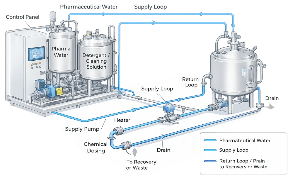
The illustration shows a representative skid, supply and return paths, a connected vessel, chemical addition, heating, and drain or recovery interfaces. Actual systems may contain separate rinse, caustic, acid, recovery, or neutralization tanks and may route to multiple users through a valve matrix.
Integration with Process Equipment
The CIP utility cannot be evaluated independently of the connected equipment. The complete cleaning circuit includes both the skid and the product-contact pathway being cleaned. Design review should address:
- supply and return connection size and location;
- spray-device type, required flow, pressure, and operating range;
- vessel geometry, baffles, agitators, dip tubes, probes, sample valves, and shadowed surfaces;
- line velocities or other hydraulic conditions required for the relevant soil and geometry;
- parallel branches and unequal flow distribution;
- trapped gas and loss of pump prime;
- high points, low points, dead ends, and hold-up volumes;
- drainability after each phase and at cycle completion;
- valve-seat, diaphragm, gasket, and instrument-port exposure;
- return restriction, backpressure, foaming, and pump interaction;
- segregation from product, other equipment, and incompatible cleaning circuits; and
- safe equipment status while a CIP route is active.
The Tank and Process Vessel Cleaning Integration article addresses spray devices, vessel geometry, drainage, sampling locations, and the process-equipment side of the interface in more detail.
Representative CIP Skid
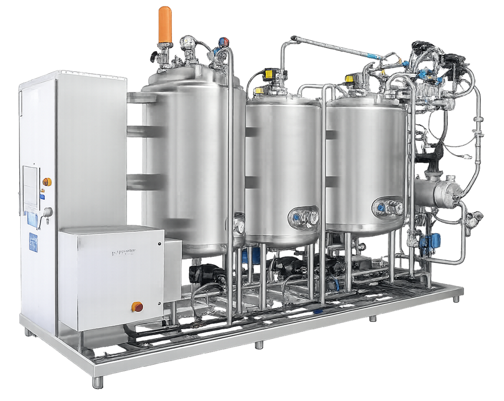
The photograph provides physical context for a multi-tank CIP skid with pumps, piping, instruments, heat-transfer equipment, valves, and an automation enclosure. The image is illustrative; the number of tanks or visible components does not determine whether the system is suitable for a specific application.
Hygienic Design and Contamination Control
The CIP system must itself be cleanable and must not become a source of residues or cross-contamination. Relevant design considerations include:
- compatible materials of construction for water, cleaning chemicals, temperatures, and expected exposure duration;
- appropriate surface condition and fabrication quality for the intended hygienic service;
- drainable equipment and piping, including tanks, valve bodies, sample ports, and instrument connections;
- control of dead legs, stagnant branches, unused connections, and temporary hoses;
- suitable slopes and support to maintain intended drainage;
- hygienic seals, gaskets, diaphragms, spray devices, and instrument interfaces;
- protection against lubricant, heat-transfer fluid, or hydraulic-fluid ingress;
- separation of concentrated chemicals from finished cleaning solutions;
- backflow prevention at water and chemical interfaces;
- segregation of returned soil from clean solution and subsequent users;
- prevention of incompatible chemical mixing in tanks, drains, or recovery systems;
- ventilation and pressure control for tanks during filling, heating, recirculation, and draining;
- access for inspection, maintenance, calibration, sampling, and safe chemical handling; and
- control of non-drainable hoses, removable parts, and temporary connections.
The design should specify how the CIP skid is cleaned after use, after maintenance, after prolonged shutdown, and when the contamination risk of one served process is not acceptable for another. A common skid does not automatically justify common recovery or reuse of cleaning fluids across all products or equipment trains.
Applicable hygienic-design practices may be drawn from the current edition of ASME BPE, facility standards, and justified engineering specifications. Use of an industry standard does not replace application-specific design review or qualification.
Operating Parameters and Cleaning Action
CIP performance results from the combined action of time, temperature, chemistry, and mechanical action. Water quality, soil condition, equipment geometry, and the time between processing and cleaning also affect the outcome. No universal velocity, temperature, conductivity, concentration, or duration is appropriate for every CIP circuit.
Principal Parameters
| Parameter or condition | Why it matters | Typical evidence |
| Flow rate or velocity | Provides transport and mechanical action in lines and equipment | Flow measurement, pump performance, circuit balance, minimum-flow challenge |
| Supply and return pressure | Supports spray-device performance and identifies restriction or abnormal routing | Pressure trends, differential evaluation, high/low alarms |
| Temperature | Affects soil removal, reaction rate, viscosity, and chemical performance | Supply/return temperature, heat-up time, hold condition, control accuracy |
| Chemical concentration | Establishes the cleaning-agent strength required for the phase | Dosing record, preparation calculation, conductivity or suitable analytical confirmation |
| Phase duration | Determines exposure after required conditions are achieved | Qualified timer logic and accumulated in-condition time |
| Conductivity | May support chemical concentration or rinse endpoint decisions | Correlation, range, temperature compensation, endpoint logic |
| Water quality | Can affect residues, microbial risk, rinse acceptance, and chemical preparation | Approved source, water-system status, use-specific requirement |
| Return condition | Provides evidence of circuit response and may control phase transitions | Return temperature, conductivity, turbidity, total organic carbon, or another justified signal |
| Spray-device condition | Affects coverage and mechanical action | Installed identity, rotation or function check, flow/pressure confirmation, inspection |
| Equipment configuration | Determines the actual flow path and surfaces exposed | Valve state, route proof, equipment status, recipe-equipment match |
| Dirty hold time | Changes soil adhesion, drying, and cleanability | Cleaning-validation challenge and operating control |
| Clean hold time | Affects protection of cleaned equipment before reuse | Cleaning-validation study and equipment-status control |
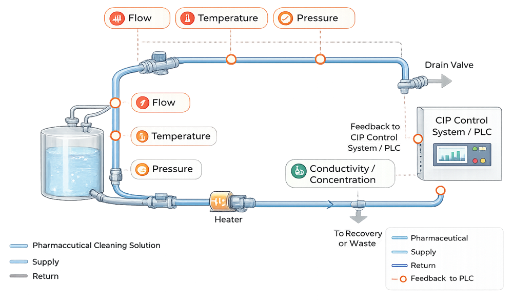
The illustration shows flow, temperature, pressure, and conductivity or concentration feedback around a representative circuit. The final control strategy may require additional variables, and not every measured variable is necessarily a critical cleaning parameter.
Parameters, Setpoints, and Acceptance Limits
The control strategy should distinguish:
- recipe target or control setpoint;
- normal operating range;
- qualified operating range;
- cleaning-validation acceptance range;
- alert level;
- alarm or action limit;
- phase-transition criterion; and
- cycle-failure criterion.
These values are related but not interchangeable. For example, the heater setpoint may be higher than the minimum required return temperature because of heat loss. A conductivity value may be used as an automated phase endpoint only after the relationship between the measured signal and the intended chemical or rinse condition has been established. A cycle can remain within an equipment safety limit yet fail the validated cleaning requirement.
Acceptance logic should also define when time begins to accumulate. Counting a ten-minute caustic phase from pump start is not equivalent to ten minutes after minimum flow, temperature, and concentration have been established at the relevant location.
Cleaning Recipes and Sequence Control
A CIP recipe is a controlled set of phases, routes, parameters, transition rules, and failure responses for a defined equipment configuration and cleaning purpose. It is not merely a list of timer settings.
A recipe may include:
- line-up confirmation and equipment permissives;
- initial drain or product displacement;
- pre-rinse;
- alkaline wash;
- intermediate rinse;
- acid wash or neutralization where required;
- final rinse;
- sanitization where part of the approved cleaning process;
- air blow, drain, or drying phase;
- final status assessment; and
- controlled release or transfer to a separate verification step.
Not every recipe uses every phase. Phase selection, order, and repetition should reflect the product soil, equipment, chemical system, water quality, microbial-control strategy, and downstream use.
Recipe Definition
Each approved recipe should identify, as applicable:
- recipe name, unique identifier, revision, and authorized equipment group;
- required equipment state and route;
- tank selection and initial volume;
- water type and temperature;
- chemical identity, dosing method, and target concentration;
- supply and return flow or pressure requirements;
- temperature target and minimum acceptable condition;
- minimum in-condition exposure time;
- recirculation, once-through, recovery, or drain destination;
- phase-completion and endpoint criteria;
- maximum interruption or hold permitted within a phase;
- restart, repeat, or abort logic;
- alarms that invalidate the phase or cycle;
- manual actions and required verification;
- data to record and review; and
- final cycle disposition.
Recipe parameters should be protected from uncontrolled editing. Temporary overrides, engineering modes, forced outputs, and manual valve operation can defeat the qualified sequence and therefore require defined authorization, recording, assessment, and restoration controls.
Transition Logic
Phase transitions may be based on time, volume, conductivity, temperature, turbidity, return condition, or a combination. The qualification strategy should verify that:
- the transition signal comes from the intended instrument;
- required conditions are simultaneously satisfied where applicable;
- signal filtering or delay does not conceal an unacceptable condition;
- the system handles noisy, frozen, missing, or implausible signals;
- a brief threshold crossing does not falsely complete a phase;
- manual advancement is prevented or controlled;
- return-to-step and repeat-step logic does not erase prior failure evidence; and
- recipe reports show the actual sequence executed, not only the intended recipe.
Automation, Electronic Records, and Data Integrity
CIP systems often combine PLC control, HMI operation, supervisory recipe management, historian data, electronic batch-record interfaces, and remote alarm functions. The automation boundary and GMP functions should be assessed as a computerized-system application, even when the PLC is supplied as part of the equipment skid.
The assessment should address:
- recipe creation, approval, download, selection, and version control;
- user roles and access privileges;
- restriction of setpoint and configuration changes;
- alarm generation, acknowledgment, shelving, and retention;
- event and operator-action records;
- audit trails where required;
- date, time, and synchronization;
- raw data, calculated values, phase summaries, and cycle reports;
- interface failure and data-buffer behavior;
- incomplete, aborted, repeated, or manually modified cycle records;
- backup, restoration, and disaster recovery;
- software, firmware, and configuration baselines;
- supplier support, patching, obsolescence, and cybersecurity; and
- retention and retrieval throughout the required record period.
The 21 CFR Part 11 Compliance and Checklist supports assessment when electronic CIP records are used to meet GMP record requirements or support cleaning-cycle acceptance.
Part 11 applicability should be determined from the predicate-rule record and how the electronic record is used. Applying Part 11 terminology does not substitute for validation of the underlying sequence, instruments, calculations, interfaces, or report logic.
Requirements, Risk Assessment, and Qualification Planning
The qualification strategy should be based on approved requirements, system boundaries, cleaning-process knowledge, and a documented evaluation of failure modes. The Risk-Based Validation Approach for GMP Systems provides the broader framework for aligning qualification evidence with GMP impact, failure consequence, control effectiveness, and uncertainty.
Relevant CIP failure modes include:
- wrong user or wrong return path selected;
- product and cleaning-chemical paths open simultaneously;
- cross-connection between equipment trains;
- inadequate flow, spray pressure, temperature, concentration, or duration;
- incorrect chemical, water type, recipe, or recipe revision;
- chemical overdosing or underdosing;
- loss of heating or excessive temperature;
- pump cavitation, loss of prime, or inadequate capacity;
- blocked spray device, line, strainer, return, or drain;
- valve fails to move or position feedback is false;
- instrument drift, failure, frozen value, or incorrect range;
- early phase transition caused by unsuitable logic or sensor location;
- return fluid sent to the wrong recovery or waste destination;
- incomplete drainage or retained chemical;
- data loss, incorrect report, time error, or unauthorized recipe change;
- interruption followed by an unjustified restart;
- maintenance contamination or incorrect reassembly; and
- common skid contamination transferred to another served system.
The plan should define:
- system and interface boundaries;
- requirements and traceability;
- critical functions, parameters, components, and records;
- commissioning and supplier evidence proposed for leverage;
- qualification prerequisites;
- installed-state, functional, hydraulic, automation, alarm, and failure tests;
- representative and worst-case circuits;
- test methods and instrument requirements;
- acceptance criteria;
- cleaning-validation dependencies and exclusions;
- deviation and discrepancy handling;
- release criteria and operating restrictions; and
- lifecycle baseline information.
Design Confirmation and Qualification Readiness
Design Qualification (DQ) should confirm that the proposed CIP architecture, capacity, hygienic design, routing, control strategy, testability, maintainability, and equipment interfaces can satisfy the approved requirements.
Qualification should not begin until the system is sufficiently complete and controlled. Readiness evidence normally includes:
- approved URS, functional specifications, design specifications, and risk assessment;
- process-flow diagrams, P&IDs, valve matrices, circuit lists, and equipment interface drawings;
- approved recipe and phase definitions;
- automation architecture, software inventory, configuration records, and alarm list;
- equipment, component, and instrument data;
- material, fabrication, weld, inspection, pressure-test, cleaning, and passivation records as applicable;
- water, steam, air, electrical, drainage, chemical, and network readiness;
- completed commissioning and supplier tests proposed for use;
- calibrated installed and test instruments;
- approved operating, maintenance, calibration, sampling, and alarm-response procedures;
- trained operators, automation support, and maintenance personnel; and
- an assessed list of open items.
Commissioning, factory acceptance testing, and site acceptance testing may support qualification when the evidence is suitable, traceable, reviewed, and accepted. Repeating a sound test adds little value; accepting an undocumented vendor demonstration adds little assurance.
Installation Qualification
Installation Qualification (IQ) establishes the approved installed baseline for the CIP system and its defined interfaces.
Applicable verification includes:
Mechanical and Process Installation
- skid, tanks, pumps, heat exchangers, filters, strainers, and dosing equipment;
- equipment identity, materials, surface finish, seals, and product-contact certificates;
- supply, return, drain, recovery, vent, overflow, and chemical piping;
- line size, slope, support, orientation, and flow direction;
- valves, manifolds, hoses, connection panels, check valves, and backflow controls;
- spray-device identity and installation where within scope;
- sample points, low points, high points, and drainage provisions;
- heat-transfer-fluid separation and leak-detection provisions;
- chemical storage, secondary containment, ventilation, and safety interfaces; and
- conformance of the installed configuration to controlled drawings.
Instrumentation and Control Installation
- instrument identity, type, range, accuracy, location, orientation, and calibration;
- PLC, HMI, supervisory nodes, panels, networks, and power supplies;
- input/output allocation and field-device association;
- software, firmware, recipe, and configuration versions;
- historian, report, alarm, and manufacturing-system interfaces;
- backup files and restoration instructions; and
- access for calibration, maintenance, inspection, and replacement.
Documentation and Lifecycle Readiness
- as-built P&IDs, wiring diagrams, panel drawings, and network diagrams;
- equipment manuals, parts lists, and recommended maintenance;
- instrument and valve lists;
- approved spare parts and critical-component strategy;
- chemical and material safety information;
- procedures and training status; and
- controlled disposition of construction and commissioning discrepancies.
Field differences should be corrected in the as-built baseline or formally evaluated. Recording an unexplained discrepancy in the IQ protocol does not make the installation acceptable.
Functional and Operational Qualification
Operational Qualification (OQ) should demonstrate that the installed CIP system operates according to approved functional requirements throughout its defined operating range and under relevant challenge conditions.
Sequence and Recipe Testing
Testing should verify:
- correct recipe availability for each authorized equipment circuit;
- recipe identity, revision, and protected parameters;
- prerequisites and permissives before cycle initiation;
- correct phase order and routing;
- chemical preparation and dosing sequence;
- heater, pump, tank-level, and mixing control;
- time accumulation only under required conditions;
- phase-transition and endpoint logic;
- repeat, pause, resume, abort, and restart behavior;
- final drain, air blow, or drying sequence;
- cycle-complete and cycle-failed status;
- report content and parameter evaluation; and
- prevention of unauthorized manual advancement or route changes.
Route and Valve Verification
Every qualified circuit should be traceable to an approved valve path. Testing should confirm:
- intended supply and return valves open;
- incompatible or nonselected paths remain closed;
- valve position feedback corresponds to actual field position;
- a missing or contradictory feedback signal prevents unsafe progression;
- product transfer and production operation are interlocked as required;
- simultaneous CIP operations are permitted only where capacity and segregation support them;
- recovery and waste routes are correctly selected; and
- connection-panel or hose arrangements cannot be silently substituted.
Parameter-Control Testing
The protocol should challenge applicable minimum, nominal, and maximum operating conditions for:
- tank volume and level control;
- supply and return flow;
- spray pressure or circuit pressure;
- heating rate and temperature control;
- chemical dosing and concentration control;
- conductivity measurement and temperature compensation;
- phase duration and accumulated exposure;
- return endpoint detection;
- cooling, neutralization, drain, and recovery functions; and
- simultaneous demand or longest-circuit operation.
Control-loop testing should establish stability, response, overshoot where relevant, and the ability to maintain the required condition. A display comparison at one steady state does not qualify a control loop.
Alarm and Interlock Testing
Applicable conditions include:
- low or high tank level;
- low supply or return flow;
- low or high pressure;
- low or high temperature;
- concentration outside range;
- chemical tank empty or dosing failure;
- pump fault or loss of prime;
- valve-position mismatch;
- route conflict;
- blocked return or abnormal backpressure;
- heater or heat-exchanger fault;
- conductivity, temperature, flow, or pressure-sensor failure;
- communication or historian failure;
- loss of power or control-system restart;
- drain, recovery, or neutralization fault; and
- emergency stop or safety-system activation.
Alarm testing should verify the complete path from initiating condition through detection, time stamp, annunciation, automatic response, operator instruction, acknowledgment, cycle status, and restoration. Merely forcing an alarm bit at the HMI does not prove field-to-record behavior.
Failure, Interruption, and Recovery Testing
Failure testing should demonstrate that a fault does not create a falsely acceptable cleaning record or an uncontrolled route. Challenges should be selected from the risk assessment and actual system design.
Sensor and Control Failures
Verify the response to a missing, frozen, implausible, out-of-range, or drifting signal when the design is intended to detect it. The system should not treat signal loss as compliance with a minimum condition. Redundant or inferred values should be challenged to confirm the selection and failover logic.
Utility and Equipment Failures
Challenge loss or degradation of water, steam or heating medium, compressed air, electrical power, network communication, chemical supply, pump capacity, and drain availability where credible. Verify safe valve states and the status assigned to the interrupted cycle.
Mid-Cycle Interruption
The approved logic should define whether a phase can resume, must restart, can be repeated, or causes complete cycle failure. The decision should consider:
- interruption duration;
- phase and cleaning agent involved;
- time outside the required temperature, flow, or concentration range;
- possible soil redeposition or chemical drying;
- route integrity during the interruption;
- equipment exposure and drain status; and
- whether the complete evidence record remains available.
An operator should not be able to convert an invalid cycle into a passed cycle by resetting an alarm, modifying a timer, or manually advancing the sequence without a recorded and approved disposition.
Recovery and Restart
Power and control-system recovery testing should confirm retained recipe state, data continuity, valve status, alarm history, time synchronization, and controlled restart. If automatic restart is permitted, its conditions and safety should be qualified. If manual assessment is required, the system should present enough information for the responsible person to make and document the decision.
Hydraulic and Equipment-Interface Verification
The common skid can function correctly while a distant or restrictive user receives inadequate cleaning conditions. Verification should therefore include representative and worst-case circuits.
Selection factors include:
- longest supply and return path;
- greatest elevation or static head;
- smallest line or most restrictive equipment path;
- largest spray-device demand;
- parallel branches with potential imbalance;
- maximum and minimum equipment volume;
- greatest heat loss;
- highest return backpressure;
- circuit most prone to air binding or cavitation;
- most difficult drainage path;
- simultaneous-use scenario; and
- equipment with the greatest consequence of inadequate cleaning.
Testing may include supply and return flow, pressure, temperature, heating time, concentration, volume balance, drainage, and repeatability. The rationale should state what each tested circuit represents and which differences require separate verification.
Spray coverage testing supports confirmation that the installed cleaning device reaches defined surfaces under the tested configuration. Coverage does not demonstrate residue removal, does not establish acceptable carryover, and does not replace cleaning validation. Likewise, a successful residue study does not establish that every alarm, route, recipe, or failure response operates correctly.
Performance Verification and Controlled Release
Performance verification should demonstrate that the qualified CIP system reproducibly delivers the defined cleaning conditions using approved operators, procedures, recipes, utilities, and representative equipment circuits. The number of runs should reflect system complexity, variability, circuit grouping, prior evidence, and risk rather than a mechanically applied number.
Evidence may include:
- repeated execution of selected recipes;
- repeatability of flow, temperature, concentration, and exposure time;
- performance of longest, largest, most restrictive, or otherwise worst-case circuits;
- correct cycle records and reports;
- return-condition and endpoint repeatability;
- acceptable drainage and route restoration;
- operator and shift coverage where relevant; and
- successful transition to the equipment or cleaning-validation study.
Qualification release should confirm:
- approved requirements and traceability are complete;
- required design, installation, functional, failure, and performance evidence is accepted;
- deviations are closed or have approved controls;
- as-built drawings and configuration records are current;
- recipes and access privileges are approved;
- calibration and maintenance programs are active;
- operating, review, alarm-response, and recovery procedures are approved;
- training is complete;
- cleaning-validation prerequisites and restrictions are identified; and
- the approved configuration and intended uses are stated.
Release of the CIP utility authorizes only the uses and conditions supported by the qualification. It does not, by itself, release an equipment cleaning process for a product.
Boundary Between CIP Qualification and Cleaning Validation
The boundary should be defined in the validation plan and protocols before execution.
| Evidence question | CIP qualification | Equipment integration | Cleaning validation |
| Is the installed skid consistent with the approved design? | Primary | Supporting | Not primary |
| Do recipes, valves, alarms, and interlocks function correctly? | Primary | Supporting | May leverage |
| Can the system deliver required flow, temperature, pressure, concentration, and time? | Primary | Shared | Uses evidence |
| Does the selected circuit reach the connected equipment under representative conditions? | Supporting | Primary | Uses evidence |
| Are spray coverage and drainage acceptable for the equipment configuration? | Supporting | Primary | Uses evidence and may challenge |
| Are product residues removed to established limits? | Not demonstrated | Not demonstrated | Primary |
| Are cleaning-agent residues controlled? | Supports rinse capability | Supports sampling and drainage | Primary |
| Are dirty and clean hold times acceptable? | Supports timer and status control | Supports equipment status | Primary |
| Are sampling locations and recovery methods suitable? | Provides sample interfaces | Identifies equipment locations | Primary |
| Does the process remain effective for worst-case product and soil conditions? | Not demonstrated | Not demonstrated | Primary |
Cleaning validation should use the qualified configuration and approved recipe. It normally addresses product and equipment grouping, worst-case product or soil, residue limits, dirty hold time, clean hold time where applicable, sampling locations, swab or rinse recovery, analytical method capability, visual inspection, microbial concerns, and reproducibility.
FDA states that the purpose of cleaning validation is to demonstrate that a cleaning process consistently cleans equipment to a predetermined standard and that sampling and analytical methods should have a sound scientific basis. FDA also explains that rinse sampling alone may be inadequate when direct surface measurement is feasible. See the FDA Questions and Answers on CGMP Requirements—Equipment and the nonbinding Guide to Inspections—Validation of Cleaning Processes.
Routine Operation and Cycle Review
Routine control should ensure that the correct approved recipe is executed on the correct equipment in the correct configuration. The operating procedure should define:
- equipment and route identification;
- pre-cycle status checks;
- chemical and water availability;
- recipe selection and verification;
- permitted manual steps;
- response to alarms and interruptions;
- criteria for cycle pass, fail, or review required;
- review of electronic or paper records;
- disposition of failed or incomplete cycles;
- equipment status labeling or electronic status control;
- protection of cleaned equipment; and
- escalation to deviation or investigation.
Automated cycle completion should not be assumed to equal quality acceptance. Where the control system evaluates critical conditions, the logic and report should make deviations visible. Where a person reviews the record, the procedure should specify which parameters, alarms, interventions, recipe versions, and exceptions must be examined.
Trends may include:
- cycle failures and aborts;
- alarms by type, circuit, recipe, or phase;
- heat-up time;
- time to reach concentration;
- rinse duration or volume;
- return conductivity or other endpoint behavior;
- flow or pressure margin;
- chemical and water consumption;
- repeated manual interventions;
- valve or instrument failures;
- maintenance frequency; and
- residue, bioburden, or verification results linked to the cleaning process.
Maintenance, Calibration, and Return to Service
Maintenance can affect hygienic integrity, routing, instrument accuracy, chemical control, recipe execution, and the validity of cleaning records. The program should cover:
- pumps, seals, bearings, and couplings;
- heat exchangers and heaters;
- tanks, mixers, vents, and level devices;
- valves, actuators, position switches, manifolds, and connection panels;
- spray devices, filters, and strainers;
- dosing pumps, chemical lines, and concentration controls;
- flow, pressure, temperature, level, conductivity, and analytical instruments;
- hoses, gaskets, diaphragms, and hygienic connections;
- drains, recovery systems, and neutralization interfaces;
- control panels, networks, power supplies, and automation hardware; and
- backup media, batteries, software, and supported replacement components.
After intrusive maintenance, repair, instrument replacement, software restoration, or route modification, the system should not automatically return to GMP service. The impact assessment should determine the required inspection, cleaning, leak or pressure testing, calibration, functional verification, route challenge, recipe regression, coverage testing, or requalification.
Like-for-like replacement is a procurement description, not a validation conclusion. Differences in wetted material, valve characteristic, actuator travel, sensor response, pump curve, heat-transfer performance, firmware, configuration, or data behavior can affect the qualified state.
Excursions and Failed Cycles
A CIP alarm, aborted recipe, missed parameter, abnormal trend, or failed cleaning result should be assessed according to its possible effect on the equipment and any product subsequently manufactured.
Immediate actions may include:
- placing the equipment and cycle record on hold;
- preventing production use;
- preserving electronic data, trends, alarms, and operator actions;
- identifying affected equipment, routes, batches, recipes, and time periods;
- inspecting valve, instrument, chemical, and equipment status;
- repeating cleaning only under an approved disposition; and
- escalating to deviation, investigation, or quality-event procedures.
The investigation should distinguish among:
- utility-delivery failure;
- incorrect recipe or configuration;
- automation or record failure;
- operator action;
- equipment integration or drainage failure;
- analytical or sampling problem; and
- true cleaning-process failure.
Repeating a CIP cycle may restore equipment cleanliness but does not explain the original failure. The investigation should determine whether prior cycles, equipment releases, or products could also be affected.
Change Control
The Change Control Impact on Validation framework should be applied to changes in the CIP skid, routes, connected equipment, recipes, automation, utilities, chemicals, procedures, and records.
Changes requiring assessment include:
- adding, removing, or regrouping a user circuit;
- changes to vessels, piping, spray devices, valves, or return restrictions;
- pump, heat exchanger, tank, or dosing-system changes;
- revised flow, pressure, temperature, concentration, time, or endpoint limits;
- recipe steps, phase order, timers, transition logic, or restart behavior;
- chemical identity, concentration, supplier, or formulation;
- water type, source, or temperature;
- instrument type, range, location, or signal processing;
- PLC, HMI, historian, interface, software, firmware, or network changes;
- alarm, interlock, access, report, or audit-trail changes;
- maintenance strategy or calibration interval changes;
- drain, recovery, reuse, or neutralization changes; and
- temporary hoses, bypasses, rental equipment, or manual workarounds.
The impact assessment should separately determine whether the change affects CIP qualification, equipment integration evidence, cleaning validation, computerized-system controls, or more than one of these. A recipe change can be functionally correct but still require cleaning revalidation because it changes the validated cleaning process.
Periodic Review and Requalification
Periodic review should evaluate accumulated evidence rather than merely confirm that documents exist. Inputs may include:
- current intended use, equipment circuits, and system boundary;
- approved recipes and configuration baseline;
- deviations, failed cycles, investigations, and CAPA;
- alarm and intervention trends;
- flow, temperature, concentration, rinse, and endpoint trends;
- cleaning-verification and validation results;
- maintenance, repair, and component-replacement history;
- calibration performance and out-of-tolerance events;
- change controls and temporary configurations;
- access reviews, audit trails, backup tests, and automation incidents;
- current drawings, procedures, and training;
- vendor support, spare parts, cybersecurity, and obsolescence; and
- previous qualification, requalification, and periodic-review actions.
The Cleaning Periodic Review article addresses review of the validated cleaning program, including products, limits, sampling, methods, deviations, and continued effectiveness.
Potential CIP requalification triggers include:
- significant skid, piping, routing, equipment, or automation changes;
- addition of a new user or new worst-case circuit;
- critical instrument or control-component replacement;
- major maintenance or intrusive repair;
- adverse parameter or reliability trends;
- repeated alarms, aborts, or unexplained manual interventions;
- failed coverage, drainage, hydraulic, or cleaning results;
- extended shutdown, relocation, or abnormal restart;
- loss of configuration or data;
- unassessed temporary operation; and
- periodic-review findings.
The Cleaning and Disinfection Revalidation Triggers article addresses when product-, residue-, equipment-, procedure-, sampling-, or analytical changes require reconsideration of the cleaning-validation evidence.
Requalification may range from documented verification of an unaffected baseline to targeted testing of a circuit, recipe, instrument, or failure response, or comprehensive requalification after major change or loss of control. The selected scope should be linked to the affected requirements, failure modes, prior evidence, and uncertainty. Repeating every original test without impact analysis is not inherently more defensible than targeted testing.
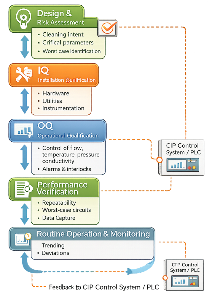
The legacy illustration shows design and risk assessment, IQ, OQ, performance verification, routine monitoring, and feedback to the control system. It should be read as a high-level lifecycle relationship, not as proof that a fixed IQ–OQ–performance-verification sequence is sufficient for every CIP application.
Regulatory and Technical Framework
For drug manufacturing, 21 CFR 211.63 requires equipment to be appropriately designed, adequately sized, and suitably located for intended use, cleaning, and maintenance. 21 CFR 211.65 addresses product-contact equipment construction and prevention of contamination from operational substances.
21 CFR 211.67 requires equipment to be cleaned, maintained, and, where appropriate, sanitized or sterilized at suitable intervals; it also requires written procedures and records for cleaning and maintenance.
Automated CIP functions and electronic records should be assessed under applicable predicate rules and 21 CFR Part 11. FDA’s Process Validation: General Principles and Practices provides the broader lifecycle principle that process knowledge, qualification, and continued verification should maintain a state of control.
These sources establish regulatory principles, not a universal CIP recipe or mandatory set of engineering values. Facility specifications and acceptance criteria should be based on the equipment, product, soil, chemical system, manufacturing process, and documented risk.
Common Control Weaknesses
Weak CIP programs commonly exhibit one or more of the following:
- treating CIP qualification and cleaning validation as the same study;
- defining the skid but omitting the receiving-equipment flow path;
- assuming one central-skid test represents every user circuit;
- applying universal flow velocity, temperature, or conductivity values without technical basis;
- starting exposure time before required conditions are achieved;
- using conductivity as an unqualified substitute for chemical concentration or residue measurement;
- testing only normal cycles and not failure or recovery behavior;
- proving an HMI alarm without challenging the field-to-record path;
- allowing uncontrolled recipe edits, overrides, manual advancement, or engineering modes;
- failing to identify the actual recipe revision used during cleaning validation;
- allowing cycle completion despite missing data or out-of-range conditions;
- neglecting drainage, return restriction, spray-device condition, or equipment configuration;
- treating coverage testing as proof of residue removal;
- repeating failed cycles without investigating the original failure;
- returning the system to use after maintenance without impact assessment;
- changing recipes or connected equipment without assessing cleaning revalidation; and
- relying on document review alone despite adverse trends or unresolved lifecycle events.
Lifecycle Outcome
A controlled CIP program establishes a traceable relationship among intended use, equipment circuits, hygienic design, cleaning recipes, operating parameters, automation, qualification evidence, cleaning validation, routine cycle records, maintenance, changes, and requalification.
The qualified CIP system must demonstrate that it can deliver and document the required cleaning conditions, including correct routing and appropriate response to failure. Cleaning validation must then demonstrate that the approved process actually achieves the required residue and contamination control on the equipment. Maintaining both evidence sets under coordinated lifecycle control prevents functional success from being mistaken for cleaning effectiveness and prevents an acceptable residue result from concealing a poorly controlled utility.