

Tank and Process Vessel Cleaning and CIP Integration
Cleaning a pharmaceutical tank is an integrated process involving the vessel, internal components, product piping, spray devices, CIP supply and return paths, cleaning recipe, instruments, automation, and drainage configuration. A qualified CIP skid cannot compensate for inaccessible vessel surfaces, inadequate spray coverage, obstructed return flow, unsuitable chemistry, or an incorrect equipment lineup.
Effective integration must be established during vessel and CIP-system design. The complete cleaning circuit should then be qualified under representative hydraulic and operating conditions before cleaning validation demonstrates removal of product residues, cleaning agents, microbial contamination, or other relevant contaminants to predefined acceptance criteria.
This article addresses the process-equipment side of tank cleaning and CIP integration. Vessel design requirements are covered in Pharmaceutical Vessel Design and Sanitary Construction, while equipment qualification is addressed in Tank and Process Vessel Qualification and Lifecycle Control. The architecture, recipes, automation, and qualification of the central CIP system are addressed in Clean-in-Place (CIP) Utility Systems.
Regulatory and Validation Context
21 CFR 211.67—Equipment Cleaning and Maintenance requires equipment and utensils to be cleaned, maintained, and, when appropriate, sanitized or sterilized at suitable intervals to prevent malfunctions or contamination that could affect product quality.
FDA’s Guide to Inspections: Validation of Cleaning Processes emphasizes written cleaning procedures, defined responsibilities, scientifically justified acceptance criteria, representative sampling, suitable analytical methods, control of cleaning delays, and documented validation evidence.
For tanks and process vessels, three related but distinct layers should be controlled:
| Layer | Primary objective |
|---|---|
| CIP utility qualification | Demonstrate that the skid, pumps, tanks, heaters, chemical dosing, routing, instruments, automation, and records operate as intended |
| Vessel–CIP integration verification | Demonstrate that the selected cleaning route provides the required flow, pressure, spray operation, surface coverage, component exposure, return conditions, and drainage |
| Cleaning validation | Demonstrate that the approved cleaning process consistently removes specified residues and contaminants to predefined acceptance criteria |
Successful execution of one layer does not establish the other two. Spray coverage does not demonstrate residue removal. A passing residue result does not prove that the CIP system operated correctly. A qualified CIP skid does not demonstrate that every connected vessel configuration is cleanable.
Cleaning Strategy and Intended Use
The cleaning strategy should be based on the actual vessel, products, soils, manufacturing sequence, and subsequent use. Relevant inputs include:
- Product or intermediate composition
- Potency and toxicological characteristics
- Solubility of product residues
- Viscosity and solids content
- Presence of oils, polymers, proteins, colorants, or insoluble materials
- Residue degradation during heating or drying
- Required microbial or endotoxin control
- Vessel geometry and internal components
- Product-contact materials
- Cleaning-agent compatibility
- Campaign and product-changeover strategy
- Dirty hold time
- Clean hold time
- Manual interventions
- Subsequent product and process stage
Cleaning arrangements may include:
- Fully automated CIP
- Semi-automated CIP with manual setup
- Manual cleaning
- Clean-out-of-place cleaning of removable components
- Combined automated and manual cleaning
- Dedicated equipment with defined between-batch cleaning
- Single-use product-contact assemblies
A vessel described as CIP-capable may still require manual cleaning of manway gaskets, removable probes, sample components, powder-addition ports, external product-contact surfaces, or other areas outside the automated circuit. These exceptions should be identified explicitly in the cleaning procedure and validation strategy.
Cleaning-System Boundary and Responsibility
The cleaning boundary should show the complete pathway through which cleaning and rinse fluids travel. It may include:
- CIP supply connection
- Vessel spray device
- Internal vessel surfaces
- Agitator shaft and impellers
- Baffles
- Dip tubes and spargers
- Product-addition ports
- Instrument probes and protective wells
- Sample valves
- Sight glasses
- Vent and filter connections
- Product-transfer piping
- Recirculation loops
- Bottom outlet valve
- CIP return or drain path
- Associated hoses, manifolds, and valve matrices
The boundary should identify interfaces between the vessel, central CIP utility, process piping, automation system, drain system, and cleaning-validation program.
Responsibilities should be assigned for:
- CIP skid ownership
- Vessel cleaning-recipe ownership
- Route configuration
- Spray-device selection and maintenance
- Cleaning-cycle initiation and review
- Equipment setup
- Manual cleaning steps
- Sampling and laboratory testing
- Cycle failure investigation
- Equipment-status release
- Change assessment
- Periodic review and requalification
A common failure is to qualify the central CIP skid to its connection point while assuming that the vessel supplier has verified everything downstream. The receiving-equipment boundary must be included in design review and integrated testing.
CIP Architecture at the Vessel Interface
A representative cleaning circuit delivers conditioned cleaning fluid from the CIP system through a selected supply route to the vessel spray device. Fluid contacts vessel surfaces and internal components, flows toward the outlet, and returns to the CIP skid or drain.
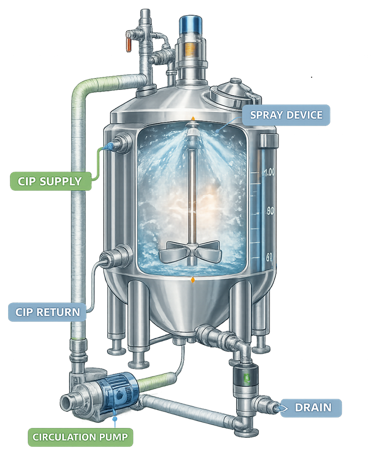
The equipment interface should define:
- Supply and return connection sizes
- Required flow and pressure range
- Available pressure at the vessel connection
- Spray-device operating requirements
- Allowable return backpressure
- Required return flow
- Vessel venting during cleaning
- Agitator operating requirements
- Required valve positions
- Cleaning of transfer piping and branches
- Drain and recovery destinations
- Isolation from product and incompatible routes
- Utility and simultaneous-demand conditions
CIP performance should be evaluated at the hydraulically limiting condition. The nearest vessel with a short return path may not represent a distant vessel connected through a long header, multiple elevation changes, restrictive valves, or shared return piping.
Simultaneous cleaning or utility demand can affect flow, temperature, chemical concentration, and heating capacity. The approved operating strategy should identify whether circuits are cleaned individually or concurrently.
Spray-Device Selection
Spray devices distribute cleaning fluid across the vessel interior and provide different combinations of wetting, cascading flow, and mechanical impact.
Fixed Spray Balls
Fixed spray balls contain stationary openings that distribute fluid in predetermined directions. Cleaning action generally relies on surface wetting, cascading liquid, chemistry, temperature, and exposure time.
Advantages include:
- Simple construction
- No moving parts
- Predictable spray pattern
- Relatively straightforward inspection
- Compatibility with many vessel sizes and applications
Limitations may include:
- Lower mechanical impact
- Dependence on continuous surface wetting
- Sensitivity to blocked holes
- Potential shadowing behind vessel internals
- Higher flow demand for some applications
Rotary Spray Heads
Rotary spray heads use flowing cleaning solution to rotate the device and distribute a dynamic pattern. They can provide broader distribution or increased impact with different hydraulic requirements from fixed spray balls.
Qualification should confirm:
- Correct rotation
- Required flow and pressure
- Complete operating cycle
- Spray pattern
- Installation orientation
- Freedom from obstruction
- Repeatable operation
A rotary device may continue to discharge fluid even when it is not rotating correctly. Flow alone therefore may not demonstrate proper operation.
Orbital or Rotary Jet Devices
Orbital and rotary jet devices produce concentrated, high-impact jets that follow a controlled pattern across the vessel interior. They may be appropriate for large vessels, difficult soils, viscous products, or complex geometry.
Their application requires attention to:
- Minimum and maximum operating pressure
- Complete pattern duration
- Jet impact
- Gear or turbine condition
- Strainer requirements
- Cycle duration
- Maintenance and inspection
- Potential damage to sensitive components
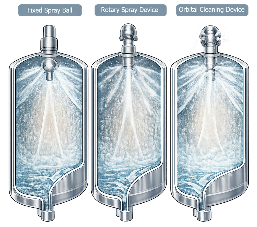
Spray-device selection should be based on vessel geometry, soil characteristics, required mechanical action, available hydraulics, internal obstructions, and cleaning-cycle objectives. One device type is not universally superior.
Placement, Shadowing, and Internal Components
Spray-device placement should allow cleaning fluid to reach product-contact surfaces and flow across them under the approved equipment configuration. Potential shadowing can be created by:
- Agitator shafts and impellers
- Baffles
- Internal coils
- Dip tubes
- Spargers
- Level probes
- Temperature sensors
- pH or conductivity probes
- Sample assemblies
- Manway structures
- Addition ports
- Sight glasses
- Vessel-head nozzles
- Valve bodies and outlet assemblies
The design review should determine whether cleaning requires:
- Agitator rotation
- Multiple spray devices
- Dedicated nozzle cleaning
- Valve pulsing or stroking
- Alternating flow paths
- Changes in liquid level
- Cleaning of both sides of an impeller
- Removal or repositioning of components
- Manual cleaning of excluded areas
Agitator operation during CIP may improve exposure but can also create splashing, foaming, air entrainment, or mechanical restrictions. The required speed, direction, liquid level, and operating phase should be defined and qualified.
Instrument probes should be exposed to cleaning solution without creating inaccessible annular spaces or recessed gasket interfaces. Retractable instruments introduce separate cleaning positions, seals, and failure modes that must be included in the cleaning procedure.
Spray Coverage Verification
Spray coverage testing is used to evaluate whether cleaning solution reaches specified internal surfaces under the tested configuration. Riboflavin or another suitable fluorescent material is frequently used for this purpose.
A controlled coverage study should define:
- Vessel and circuit identification
- Equipment configuration
- Spray-device identity and position
- Agitator and internal-component configuration
- Riboflavin preparation and application
- Pre-test inspection
- CIP flow and pressure
- Test duration
- Agitator operation
- Lighting and inspection conditions
- Acceptance criteria
- Documentation method
- Treatment of ambiguous or inaccessible areas
The challenge material should be applied to representative areas, including potential shadow locations. Application should not be so light that absence cannot be confirmed or so heavy that removal requires conditions unrelated to normal surface wetting.
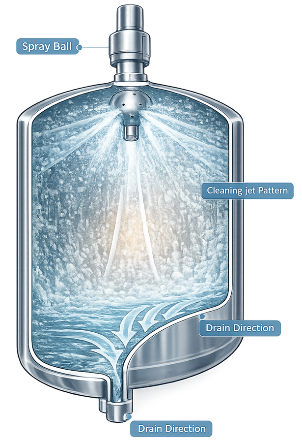
Coverage testing should be interpreted correctly:
- It demonstrates coverage or wetting under the tested conditions.
- It can identify obvious shadowed or unexposed areas.
- It supports qualification of spray-device placement and hydraulic conditions.
- It does not establish removal of actual product soil.
- It does not replace cleaning validation.
- It does not demonstrate that the chemical concentration, temperature, or exposure time is adequate.
- It does not remain automatically applicable after changes to vessel internals, spray devices, hydraulics, or operating configuration.
Coverage testing should be repeated or assessed following changes that could alter the spray pattern or surface exposure.
Cleaning Parameters and Operating Envelope
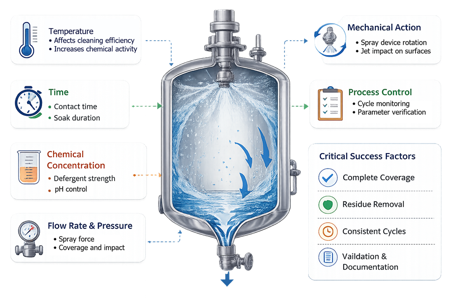
Cleaning performance results from the combined action of time, temperature, chemistry, and mechanical action. Water quality, soil condition, equipment geometry, and cleaning delay also affect the result.
Important parameters and conditions include:
| Parameter or condition | Cleaning significance |
|---|---|
| Flow rate | Establishes fluid delivery, surface wetting, line transport, and spray-device operation |
| Supply pressure | Supports spray-device performance and can indicate restriction |
| Return pressure | Affects spray operation, return flow, and pump performance |
| Temperature | Affects chemical action, solubility, viscosity, and soil removal |
| Chemical concentration | Establishes the required cleaning-agent strength |
| Phase duration | Establishes exposure after required operating conditions are achieved |
| Conductivity | May support concentration confirmation or rinse endpoint control |
| Water quality | Can affect residue removal, rinse acceptance, and microbial control |
| Equipment configuration | Determines the route and product-contact surfaces exposed |
| Dirty hold time | Affects drying, adhesion, degradation, and cleanability |
| Agitator operation | Can affect exposure of internal components and liquid movement |
| Drainage | Removes soil, chemicals, rinse water, and retained moisture |
The existing filename contains a spelling error and can remain unchanged to avoid unnecessary media replacement.
No universal CIP velocity, temperature, chemical concentration, or duration is appropriate for every vessel. Operating limits should be established from equipment capability, chemical compatibility, soil-removal studies, cleaning development, and validation evidence.
The control strategy should distinguish:
- Recipe setpoint
- Normal operating range
- Qualified equipment range
- Validated cleaning range
- Alert level
- Alarm or action limit
- Phase-transition condition
- Cycle-failure criterion
These values are related but are not interchangeable. A cycle can remain within an equipment safety limit while failing a validated cleaning requirement.
Cleaning Recipes and Sequences
A CIP recipe is a controlled sequence of routes, phases, parameters, transitions, and failure responses for a defined equipment configuration.
A representative recipe may include:
- Equipment lineup and permissive verification
- Product displacement or initial drain
- Pre-rinse
- Alkaline wash
- Intermediate rinse
- Acid wash or neutralization where required
- Final rinse
- Sanitization where required
- Air blow, drain, or drying phase
- Final cycle evaluation
- Equipment-status transition
Not every cleaning process requires every phase. The sequence should be justified by the soil, cleaning agent, water quality, equipment, microbial-control strategy, and subsequent use.
Each approved recipe should define:
- Recipe name, number, and revision
- Authorized vessel or equipment group
- Required equipment setup
- Route and valve configuration
- Water type
- Cleaning-agent identity
- Target concentration
- Supply and return flow or pressure
- Temperature requirements
- In-condition exposure time
- Agitator operation
- Phase-transition criteria
- Maximum permitted interruption
- Alarm and failure conditions
- Restart, repeat, or abort logic
- Drain or recovery destination
- Required records
- Final disposition method
Time should accumulate only after the required cleaning conditions are achieved at the relevant location. Counting a wash phase from pump start is not equivalent to counting after minimum flow, temperature, concentration, and return conditions have been established.
Dirty Hold Time and Cleaning Delay
Dirty hold time is the interval between completion of processing and initiation of the defined cleaning process. Delayed cleaning can allow residues to:
- Dry or harden
- Polymerize
- Crystallize
- Adhere more strongly
- Degrade into less-soluble compounds
- Support microbial growth
- Become more difficult to remove
The dirty-hold-time definition should identify the start and endpoint. Initial product displacement, water flushing, manual pre-cleaning, or keeping equipment wet may change the relevant challenge and should be controlled.
Cleaning validation should represent the established maximum dirty hold time or provide a justified bracketing strategy. Routine records should demonstrate that the approved limit was met.
Drainage, Drying, and Storage
After each CIP phase, displaced soil and cleaning chemicals must leave the vessel through the intended return or drain path. Inadequate drainage can dilute subsequent phases, retain detergent, increase microbial risk, and interfere with drying.
Drainage depends on:
- Vessel-bottom geometry
- Installed vessel level
- Outlet location
- Bottom-valve design
- Internal-component geometry
- Branch orientation
- Valve-body drainage
- Return-line slope
- Hose configuration
- Venting
- Fluid viscosity and surface behavior
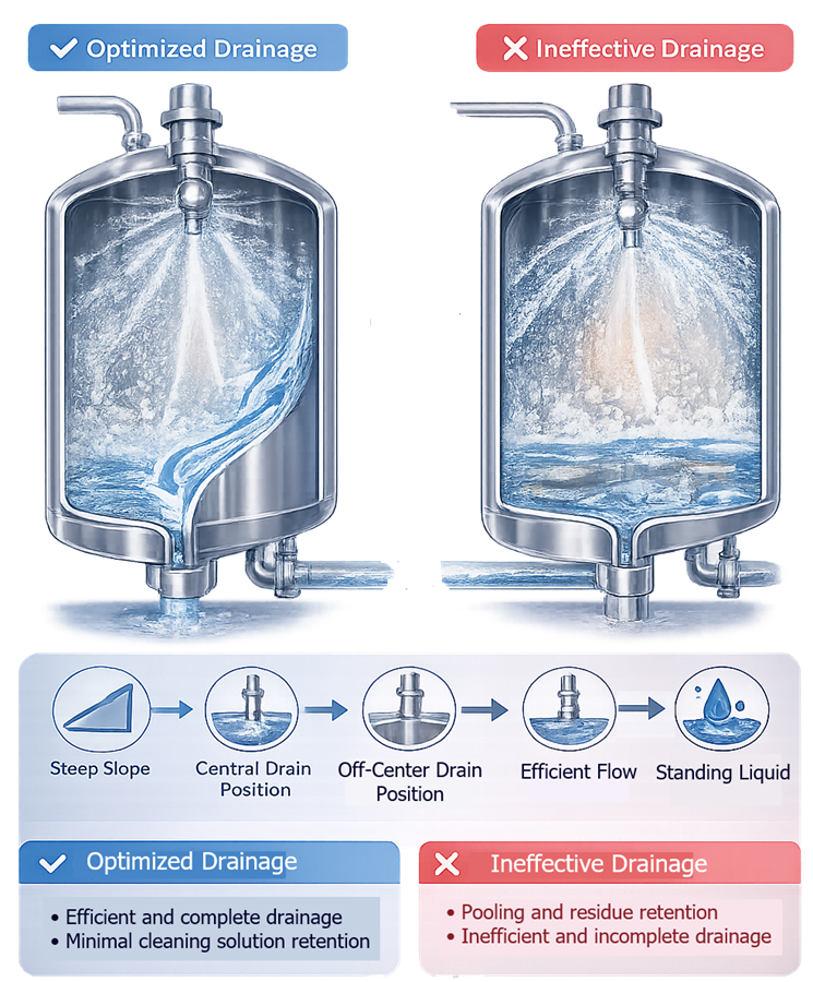
Drainability should be assessed using a defined method and endpoint. “Visually drained” may be appropriate for one application, while another may require measurement of residual volume, drainage time, conductivity, moisture, or low-point condition.
The post-cleaning strategy should define whether the vessel is:
- Left wet
- Drained and closed
- Air blown
- Dried with filtered gas
- Sanitized
- Steam sterilized
- Maintained under positive pressure
- Stored open under controlled conditions
Stagnant water should not remain unintentionally after cleaning. Storage conditions should protect the cleaned equipment and support the approved clean hold time.
Automation and Electronic Records
Automated tank cleaning may involve the vessel controller, CIP skid controller, supervisory system, historian, recipe server, and manufacturing or laboratory interfaces.
The integrated automation should control or record:
- Vessel and route selection
- Valve positions
- Pump operation
- Spray-device operating conditions
- Flow and pressure
- Supply and return temperature
- Chemical dosing and concentration
- Conductivity
- Phase duration
- Agitator operation
- Drain and recovery destination
- Alarm and interlock status
- Operator actions
- Cycle completion and disposition
Route permissives should prevent:
- Cleaning the wrong vessel
- Sending cleaning chemicals into a product path
- Connecting incompatible equipment
- Simultaneous product processing and cleaning
- Incorrect return or drain routing
- Starting a cycle with an unavailable spray or return path
- Advancing a phase before required conditions are met
The design should address instrument failure, frozen signals, valve-position disagreement, communication loss, power interruption, aborted cycles, manual advancement, overrides, and recovery after failure.
Electronic records should show what actually occurred, including:
- Recipe and revision
- Equipment and route
- Cycle start and completion
- Actual phase sequence
- Parameter trends
- Alarm and event history
- Operator interventions
- Repeated or skipped phases
- Cycle interruptions
- Final status
A summary stating “cycle complete” is inadequate if the underlying record does not show whether validated conditions were maintained.
Equipment Qualification Versus Cleaning Validation
Tank and CIP qualification establishes that the equipment can execute the required cleaning process. Relevant qualification activities may include:
- Installed-component verification
- Spray-device identity and orientation
- Instrument calibration
- Flow and pressure testing
- Heating capability
- Chemical-dosing functions
- Recipe and sequence testing
- Valve-route verification
- Spray coverage
- Agitator operation
- Drainability
- Alarm and failure-response testing
- Data recording and reporting
Cleaning validation then uses the qualified equipment and approved procedure to demonstrate residue removal under defined worst-case or representative conditions.
The broader validation strategy—including residue selection, acceptance limits, worst-case products, analytical methods, recovery, study design, and revalidation—is addressed in Cleaning Validation Approach.
Qualification evidence should be available before or incorporated into cleaning-validation execution. Otherwise, a failed cleaning study may be impossible to distinguish from an equipment, instrument, recipe, or cleaning-process failure.
Sampling Locations and Access
Sampling locations should be selected according to equipment geometry, soil behavior, cleaning difficulty, accessibility, and the capability of the sampling method.
Potential worst-case locations include:
- Vessel-head surfaces
- Agitator shaft and underside of impellers
- Baffles
- Internal coils
- Welds and surface transitions
- Manway gasket
- Addition ports
- Instrument probes
- Sample valves
- Bottom outlet valve
- Dip tubes and spargers
- Transfer-line branches
- Valve seats
- Spray-shadow areas
- Low points
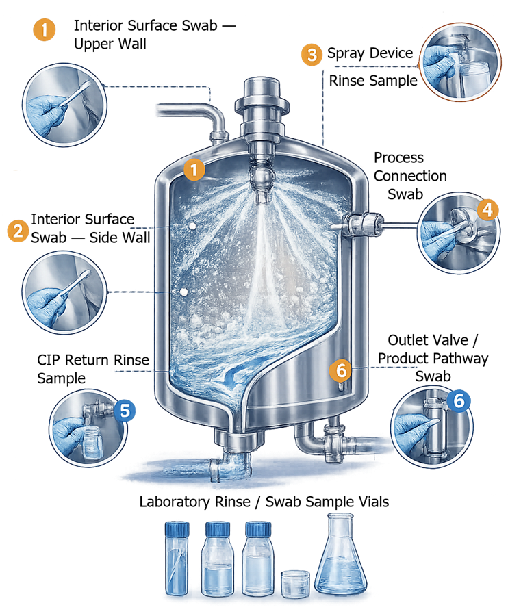
Swab Sampling for Cleaning Validation provides direct evidence from a defined accessible surface. Sampling recovery should be established for the relevant residue, surface, swab, solvent, and analytical method.
Rinse Sampling for Cleaning Validation can evaluate larger or inaccessible portions of the equipment, but the result depends on residue solubility, rinse distribution, sample location, rinse volume, and calculation basis.
Rinse sampling should not be assumed to represent every internal surface equally. A clean rinse result can coexist with an isolated residue trapped behind a gasket, under an impeller, or in an inadequately exposed branch.
Visual inspection remains an important control because localized residue may be missed by a limited analytical sampling plan. Visual inspection conditions, accessibility, lighting, acceptance criteria, and inspector training should be defined.
Cleaning-Cycle Review and Equipment Release
Routine release should be based on predefined evidence rather than the absence of an obvious alarm.
Review may include:
- Correct vessel and recipe
- Correct recipe revision
- Complete cycle sequence
- Required parameter conditions
- Required accumulated exposure time
- Acceptable alarms and interventions
- Final-rinse condition
- Drainage completion
- Required visual inspection
- Required analytical results
- Equipment assembly and closure
- Equipment-status identification
- Clean-hold-time start
The procedure should distinguish:
- Successfully completed cycle
- Aborted cycle
- Interrupted but recoverable cycle
- Failed cycle
- Cycle requiring investigation
- Cycle requiring complete repetition
- Equipment requiring additional cleaning
- Equipment prohibited from release
Testing or cleaning repeatedly until an acceptable result is obtained does not demonstrate that the original cleaning process was effective. Additional cleaning and resampling require documented assessment of the failure, equipment status, and effect on validated conditions.
Failure Investigation
Cleaning failures may arise from equipment, automation, procedure, chemistry, product soil, sampling, or analytical causes.
Potential causes include:
- Wrong recipe or route
- Inadequate flow or pressure
- Blocked or damaged spray device
- Rotary device not rotating
- Incorrect temperature
- Incorrect chemical concentration
- Insufficient exposure time
- Excessive dirty hold time
- Incorrect agitator operation
- Shadowed or manually excluded surface
- Incomplete valve actuation
- Restricted return path
- Poor drainage
- Instrument drift or failure
- Unauthorized manual intervention
- Incorrect sampling location
- Inadequate sampling recovery
- Analytical error
- Product or formulation change
Investigation should preserve the original cycle record and distinguish equipment capability from cleaning-process effectiveness. Retesting should not replace identification of the cause and assessment of potentially affected equipment or batches.
Lifecycle Control and Requalification
Changes affecting the cleaning circuit should be assessed before implementation whenever practical.
Potential triggers include:
- New product or formulation
- Changed residue limit
- New cleaning agent
- Changed chemical concentration
- Changed water quality
- Revised cleaning temperature or duration
- Extended dirty or clean hold time
- Spray-device replacement
- Changed spray-device position
- Agitator or impeller modification
- New probe, baffle, coil, or internal component
- Vessel or piping repair
- Gasket or valve change
- Modified CIP supply or return path
- Pump, heater, or instrument replacement
- Recipe, software, alarm, or interlock change
- Repeated cleaning failures
- Adverse monitoring trend
- Extended shutdown
- Equipment relocation
The impact assessment should determine whether the change requires:
- Documentation update
- Inspection or calibration
- Targeted functional testing
- Repeat hydraulic testing
- Repeat spray coverage
- Repeat drainability testing
- CIP system requalification
- Cleaning-validation assessment
- Targeted revalidation
- Comprehensive cleaning revalidation
Periodic review should consider cleaning-cycle trends, alarms, deviations, maintenance, calibration, recipe changes, spray-device condition, cleaning-validation monitoring, visual-inspection findings, analytical results, and unresolved corrective actions.
Documentation Package
Controlled cleaning and CIP documentation may include:
- Cleaning-boundary drawing
- Process and instrumentation diagram
- CIP supply and return route
- Vessel and spray-device specifications
- Spray-device operating requirements
- Cleaning-development report
- Approved cleaning recipe
- Equipment setup instructions
- Manual cleaning instructions
- Instrument and alarm list
- Coverage-test protocol and report
- Hydraulic test records
- Drainability assessment
- Qualification protocols and reports
- Cleaning-validation protocol and report
- Sampling-location drawings
- Analytical and recovery studies
- Cycle-review procedure
- Equipment-release procedure
- Failure-investigation records
- Change controls
- Requalification and revalidation assessments
- Periodic-review records
Documents should distinguish the qualified equipment operating range from the validated cleaning operating range and routine recipe setpoints.
Conclusion
Successful tank cleaning depends on integration of vessel geometry, internal components, spray devices, CIP hydraulics, cleaning chemistry, time, temperature, automation, drainage, sampling access, and lifecycle control.
CIP utility qualification demonstrates that the cleaning system can operate as designed. Vessel-integration testing demonstrates that cleaning conditions reach the connected equipment. Cleaning validation demonstrates that the approved process removes specified residues and contaminants to justified acceptance criteria.
Maintaining these distinctions creates a defensible evidence chain from equipment design through routine cleaning, equipment release, change control, periodic review, and revalidation.