

Tank and Process Vessel Qualification and Lifecycle Control
Pharmaceutical tank and process vessel qualification must demonstrate that the installed system is suitable for its intended use, operates reproducibly across its approved range, protects product quality, and remains controlled throughout its lifecycle.
The qualification boundary normally extends beyond the vessel shell. Depending on intended use, it may include agitation, thermal control, instruments, automation, valves, product-transfer paths, venting, pressure and vacuum protection, clean-in-place connections, steam-in-place interfaces, and associated utilities. Qualification gaps occur when these interfaces are divided among separate equipment packages without clear ownership or integrated testing.
This article addresses qualification and lifecycle control for fixed and portable pharmaceutical tanks, preparation vessels, formulation vessels, hold tanks, receivers, and related process vessels. Vessel classifications and materials are covered in Pharmaceutical Tank and Process Vessel Types, Functions, and Materials. Design requirements are addressed in Pharmaceutical Tank and Process Vessel Design: Sanitary Construction and System Integration. Equipment-side cleaning requirements are addressed in Tank and Process Vessel Cleaning and CIP Integration.
Regulatory and Lifecycle Basis
21 CFR 211.63—Equipment Design, Size, and Location requires manufacturing equipment to be appropriately designed, adequately sized, and suitably located for its intended use, cleaning, and maintenance.
For automated vessels, 21 CFR 211.68—Automatic, Mechanical, and Electronic Equipment establishes requirements relevant to the routine checking, calibration, inspection, and control of automated equipment and authorized changes.
FDA’s Process Validation: General Principles and Practices places equipment design and qualification within a lifecycle extending from process design through commercial production and continued verification.
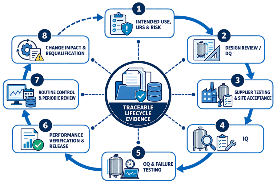
Qualification should therefore be treated as a connected lifecycle rather than as three isolated protocol labels:
- Intended use, user requirements, and risk assessment
- Design review and design qualification
- Supplier testing and site acceptance
- Installation qualification
- Operational qualification and failure testing
- Process-relevant performance verification and release
- Routine control and periodic review
- Change-impact assessment and requalification
Intended Use and Qualification Boundary
The qualification strategy should begin with a concise intended-use statement defining:
- Vessel function
- Products, intermediates, buffers, media, or utilities processed
- Batch-size and operating-volume range
- Required mixing or holding function
- Temperature range
- Pressure and vacuum conditions
- Required microbial or contamination-control state
- Cleaning, sanitization, or sterilization method
- Product additions, sampling, and transfer operations
- Required instrumentation and automation
- Connected systems and utilities
- Approved operating environment
The qualification boundary should be shown on an approved drawing or system-boundary document. It may include:
- Vessel shell, heads, supports, insulation, and identification
- Agitator motor, drive, shaft, impellers, baffles, and seals
- Heating or cooling jacket
- Product-contact valves and piping
- Addition, sampling, vent, transfer, and drain connections
- Spray devices and cleaning connections
- SIP supply, vent, and condensate paths
- Temperature, pressure, level, weight, speed, pH, conductivity, or other instruments
- Pressure-relief and vacuum-protection devices
- Local control panel, programmable controller, and operator interface
- Transfer pumps or recirculation loops
- Utility interfaces
- Relevant electronic records and reports
The boundary should identify the interface with central Clean-in-Place (CIP) Utility Systems and Steam-in-Place (SIP) Utility Systems. Separate qualification packages may be used, but the integrated functions must not be omitted.
Requirements and Risk-Based Qualification Planning
The user requirements specification should define requirements that can be traced to design features and verification evidence. Requirements may include:
- Working and total volume
- Minimum operating volume
- Agitator type and speed range
- Mixing or suspension objective
- Heating and cooling performance
- Product-temperature range
- Pressure and vacuum rating
- Product-contact materials
- Surface-finish requirements
- Drainability or retained-volume limits
- Addition, sampling, and transfer functions
- Venting and sterile-boundary requirements
- Instrument ranges and accuracy
- Alarm and interlock functions
- CIP and SIP capability
- Automation and data requirements
- Maintenance and calibration access
- Required supplier documentation
Risk assessment should identify failure modes that could affect product quality, process control, equipment integrity, contamination control, or reliable records.
Representative vessel failure modes include:
- Agitator fails to start, stops unexpectedly, or operates at the wrong speed
- Mixing is ineffective at minimum or maximum operating volume
- Temperature control exceeds or fails to reach its required range
- Level or weight measurement is inaccurate
- Product is retained after transfer or drainage
- A process valve fails to move or reports an incorrect position
- Vent restriction causes excessive pressure or vacuum
- Pressure-relief or vacuum-protection functions are unavailable
- Cleaning solution does not reach a product-contact surface
- A CIP phase operates below required flow, temperature, concentration, or duration
- Air or condensate remains during SIP
- An instrument fails, freezes, drifts, or supplies an implausible value
- An alarm is not generated, recorded, or acted upon as designed
- A recipe, setpoint, or sequence can be changed without authorization
- Power or communication loss leaves the vessel in an unsafe or indeterminate state
- A portable vessel is connected to the wrong process path
- Maintenance or component replacement alters the product-contact boundary
The risk assessment should influence test depth, operating-range challenges, failure tests, documentation requirements, and requalification strategy. It should not be used merely to justify eliminating testing.
Design Qualification and Design Review
Design qualification, or an equivalent documented design review, should demonstrate that the proposed design satisfies approved requirements and addresses identified risks.
The review should evaluate:
- Vessel geometry and usable-volume range
- Materials of construction and compatibility
- Product-contact surface condition
- Weld and fabrication requirements
- Drainability and product recovery
- Agitation and mixing configuration
- Heating and cooling capacity
- Instrument type, range, accuracy, and location
- Product additions, sampling, venting, transfer, and discharge
- Pressure and vacuum design
- Protective devices
- CIP spray-device placement and hydraulic requirements
- SIP venting, air removal, and condensate drainage
- Automation architecture and operating sequences
- Alarm, interlock, and failure-response design
- Utility capacity and connection requirements
- Maintenance, calibration, and inspection access
- Supplier-documentation commitments
- Qualification testability
Design review should involve the appropriate combination of process engineering, manufacturing, validation, quality, automation, maintenance, safety, and supplier personnel.
Approval should not be based only on a supplier’s statement that the equipment is “pharmaceutical grade” or compliant with an industry standard. Application-specific suitability must be established against the approved intended use and requirements.
Supplier Testing and Site Acceptance
Factory acceptance testing can detect fabrication, control, and documentation deficiencies before shipment. Site acceptance testing confirms equipment condition after delivery and verifies functions dependent on the final installation.
Factory Acceptance Testing
FAT scope may include:
- Equipment and component identification
- Dimensional and visual inspection
- Surface and weld-documentation review
- Material-certificate review
- Pressure or leak testing
- Agitator operation
- Instrument and valve checks
- Control-panel inspection
- Recipe and sequence demonstrations
- Alarm and interlock testing
- Operator-interface review
- Software and configuration identification
- Documentation-package review
- Verification of shipment and preservation requirements
FAT conditions should be recorded. Tests performed with temporary utilities, simulated instruments, water instead of product, or incomplete automation may still provide useful evidence, but their limitations must be understood.
Site Acceptance Testing
SAT may address:
- Shipping damage and preservation
- Equipment completeness
- Final assembly
- Installed utility connections
- Motor rotation
- Valve and instrument connections
- Communication with site automation
- Safety circuits
- Initial energization
- Basic operating sequences
- Open FAT issues
- Readiness for formal qualification
Supplier testing may be leveraged when it is approved, attributable, technically adequate, performed under controlled conditions, and applicable to the final installed configuration. Qualification protocols should identify which evidence is accepted, repeated, supplemented, or excluded.
Installation Qualification
Installation qualification verifies that the installed vessel and associated components conform to approved design documents and are ready for functional testing.
Equipment and Installation Verification
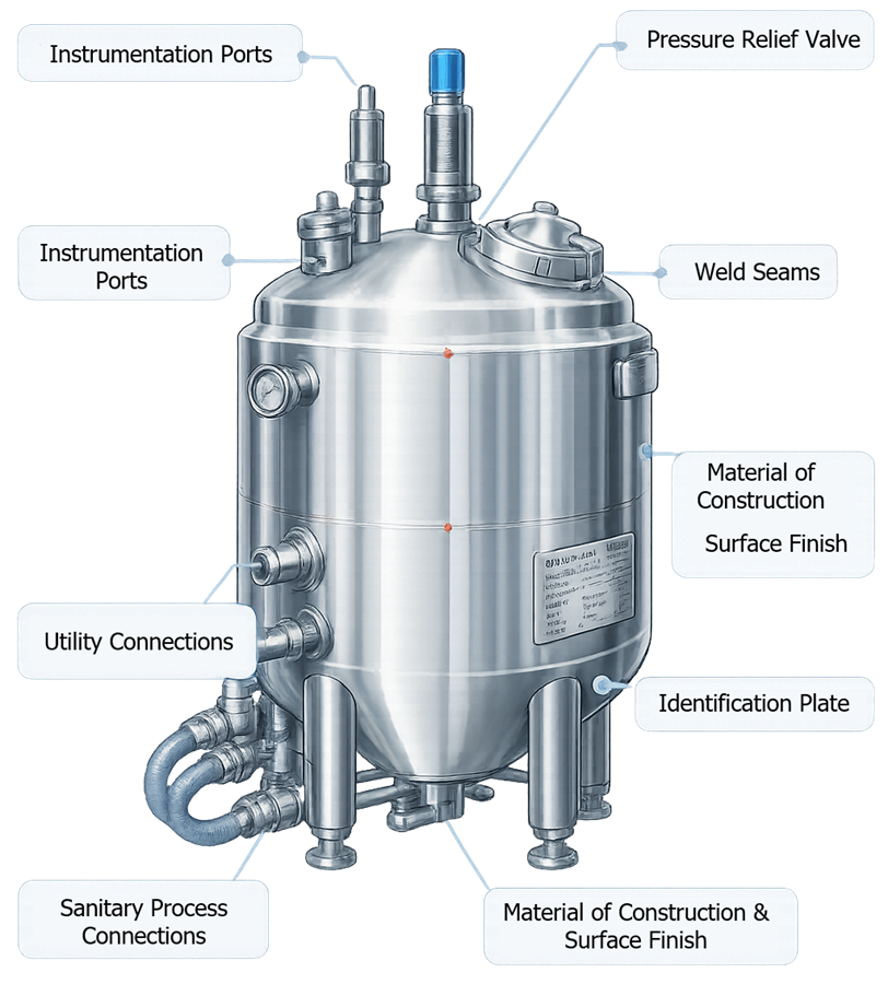
IQ should verify, as applicable:
- Manufacturer, model, serial number, asset number, and equipment tag
- Installation location and orientation
- Vessel dimensions and rated capacity
- Working-volume markings or measurement basis
- Supports, legs, frame, anchorage, and load cells
- Equipment leveling and intended drainage orientation
- Agitator motor, gearbox, shaft, impeller, and seal
- Jacket identification and rating
- Product-contact valves and piping
- Addition, sample, vent, transfer, and drain connections
- Spray devices and cleaning connections
- Pressure-relief and vacuum-protection devices
- Instrument identification, range, and installation
- Utility connections and service identification
- Electrical and pneumatic connections
- Control panel and automation hardware
- Safety guards and emergency controls
- Insulation and external finish
Materials and Fabrication Records
The IQ review should confirm availability and acceptability of applicable:
- Material certificates
- Product-contact material traceability
- Elastomer and gasket documentation
- Weld maps
- Welding-procedure and personnel qualifications
- Weld-inspection records
- Repair records
- Surface-finish records
- Passivation or electropolishing records
- Pressure-test documentation
- Mechanical-code records
- Supplier release documentation
Documentation should be reconciled with the installed equipment. A certificate for a component that cannot be connected to the installed tag, heat number, weld map, or bill of materials provides limited traceability.
Drawings and Documentation
Required documents may include:
- User requirements specification
- Approved design specifications
- General arrangement drawings
- Fabrication drawings
- Process and instrumentation diagrams
- System-boundary drawings
- Electrical drawings
- Instrument and alarm lists
- Valve and component lists
- Control and functional specifications
- Software and configuration records
- Operating and maintenance manuals
- Calibration instructions
- Recommended spare-parts information
Redlined drawings should be resolved before final approval or controlled through a defined post-qualification action. Qualification should establish the verified installed baseline rather than perpetuate inaccurate design records.
Instrument Calibration
Instruments used during qualification should have current calibration traceable to appropriate standards. The review should confirm:
- Instrument identification
- Measurement range
- Required accuracy
- Calibration points
- Acceptance tolerance
- Calibration status
- Installation orientation
- As-found and as-left results where applicable
- Impact assessment for out-of-tolerance findings
Calibration confirms measurement performance under the calibration procedure. It does not verify alarm logic, control response, report calculations, or suitability of the sensor location.
Operational Qualification
Operational qualification demonstrates that the vessel and associated functions operate as intended throughout defined operating ranges.
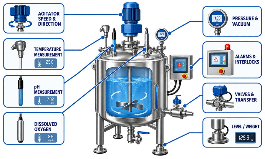
OQ should use approved procedures, calibrated test instruments, traceable requirements, and predefined acceptance criteria.
Agitation and Mixing Functions
Testing may include:
- Start, stop, and direction of rotation
- Speed setpoint and actual-speed indication
- Minimum and maximum approved speeds
- Acceleration and deceleration
- Low-level permissive
- High-speed protection
- Motor overload response
- Agitator alarm functions
- Power-loss and restart behavior
- Manual and automatic mode
- Recipe-controlled speed changes
- Seal-support functions where applicable
- Abnormal vibration or noise assessment
Mechanical agitator operation does not by itself demonstrate process mixing performance. Process-relevant mixing verification is addressed separately.
Heating and Cooling Functions
Testing should represent the approved operating range and may include:
- Heating and cooling initiation
- Temperature setpoint control
- Sensor agreement
- Heat-up and cool-down time
- Temperature overshoot
- Control-valve response
- Jacket supply and return behavior
- High- and low-temperature alarms
- Loss of utility
- Sensor failure
- Agitation dependency
- Minimum- and maximum-volume conditions
- Power-loss and restart response
Acceptance criteria should be based on process requirements and equipment capability rather than arbitrary control stability.
Level, Weight, and Volume Functions
Testing may include:
- Zero and span response
- Accuracy at representative operating points
- Minimum detectable level or weight
- High- and low-level alarms
- Pump or agitator permissives
- Filling and discharge transitions
- Load-cell response after piping and hose connections
- Recipe quantity calculations
- Overfill protection
- Response to signal loss or implausible values
Where load cells are used, testing should confirm that piping loads, flexible connections, supports, and installed accessories do not create unacceptable error.
Valve, Transfer, and Drain Functions
Testing may include:
- Valve command and position feedback
- Fail position
- Route permissives
- Prevention of incompatible lineups
- Transfer-pump operation
- Low-level pump protection
- Transfer-rate capability
- Prevention of reverse flow
- Drain sequence
- Product-recovery or retained-volume verification
- Manual-operation controls
- Response to valve or pump failure
Drainability testing should use an approved method and defined endpoint. Visual observation, collected residual volume, elapsed drainage time, or another measure may be appropriate depending on the requirement.
Pressure, Vacuum, and Venting Functions
Testing should address normal and credible abnormal conditions without exceeding safe equipment limits. It may include:
- Pressure-control response
- Vacuum-control response
- Pressure and vacuum alarms
- Regulator operation
- Vent-path availability
- Protective-device status
- Blocked-vent detection where provided
- Gas-overlay control
- Loss of gas supply
- Pressure decay or leak testing
- Power or instrument failure response
Formal activation of a relief device may not always be appropriate during OQ. Documentation review, calibration or certification, setpoint verification, functional testing under controlled conditions, and inspection may be combined according to the device and risk.
Automation, Alarms, and Failure Testing
Automated vessels should be tested as integrated computerized equipment rather than as isolated mechanical components.
Testing should address:
- User access and role restrictions
- Recipe selection and authorization
- Setpoint limits
- Operating modes
- Sequence steps and transitions
- Instrument scaling
- Calculations and displayed values
- Valve and equipment status
- Alarm generation and acknowledgment
- Interlock operation
- Manual operations and overrides
- Audit trails where required
- Electronic records and reports
- Time and date handling
- Interface communication
- Power interruption
- Restart and recovery
- Backup and restoration
- Software and configuration identification
Failure testing should challenge credible abnormal conditions, including:
- Sensor signal high, low, frozen, missing, or implausible
- Valve failure to open or close
- Loss of position feedback
- Agitator trip
- Loss of heating or cooling
- Excessive temperature
- Low or high level
- Loss of instrument air
- Loss of electrical power
- Communication failure
- Incorrect route request
- Attempted operation outside approved limits
- Interrupted CIP or SIP sequence
The expected safe state, alarm, operator action, record, and recovery method should be defined before testing.
Cleaning and CIP Integration Verification
Equipment qualification and cleaning validation have different objectives:
- Vessel qualification verifies that cleaning-related equipment, instruments, routes, spray devices, controls, and sequences operate as intended.
- Cleaning validation demonstrates that the approved cleaning process consistently removes residues and relevant contaminants to predefined acceptance criteria.
Qualification activities may include:
- Spray-device identification and installation
- Required CIP flow and pressure
- Spray coverage
- Supply and return temperature
- Cleaning-solution routing
- Valve sequencing
- Return-path operation
- Agitator operation during cleaning
- Drainage after each phase
- Alarm and interruption response
- Cycle-data recording
- Recipe and access control
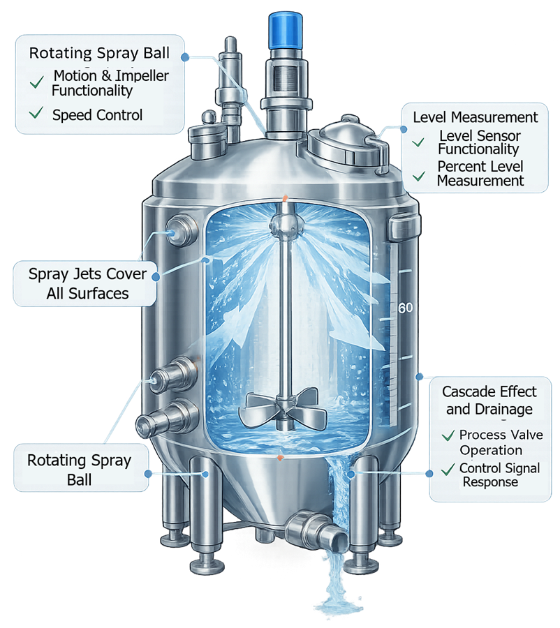
Coverage testing demonstrates that cleaning solution reaches targeted surfaces under the tested configuration. It does not demonstrate residue removal or replace cleaning validation.
The integrated equipment and cleaning strategy is addressed in Tank and Process Vessel Cleaning and CIP Integration.
SIP Capability and Sterilization Boundary
For vessels requiring steam-in-place, equipment qualification should verify that the installed system can support development and validation of the sterilization process.
Testing may address:
- Steam supply and isolation
- Defined sterilization boundary
- Vent and bleed paths
- Air removal
- Condensate drainage
- Trap and low-point operation
- Temperature-instrument installation
- Jacket operating mode
- Pressure control
- Sterile vent-filter configuration
- Valve sequencing
- Heating and cooling transitions
- Alarm and abort logic
- Post-cycle pressure management
- Maintenance of the closed or sterile state
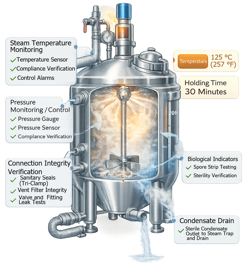
Equipment qualification should not claim sterilization solely because a programmed cycle reaches a displayed temperature. Sterilization-process validation requires representative physical and, where applicable, biological evidence across the defined system boundary. The integrated process is addressed in Steam-in-Place (SIP) Utility Systems.
Process-Relevant Performance Verification
The term performance qualification is used differently across organizations. For tanks and process vessels, the required studies should be defined by objective rather than assigned automatically to a protocol labeled “PQ.”
Process-relevant performance verification may include:
- Mixing-time studies
- Concentration uniformity
- Temperature uniformity
- Dissolution performance
- Suspension or settling behavior
- Minimum- and maximum-volume performance
- Heating and cooling under representative load
- Product or surrogate transfer
- Product recovery
- Hold-condition maintenance
- Sampling representativeness
- Interface with upstream or downstream equipment
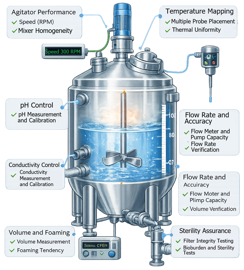
Water or another surrogate may be appropriate for selected equipment-capability studies. It may be inadequate where product viscosity, density, solids behavior, foaming, heat transfer, or surface interaction materially affects performance.
Equipment performance verification does not replace process performance qualification. The vessel may demonstrate adequate mechanical and control capability while product-specific evidence remains necessary for mixing, dissolution, suspension, reaction, hold time, or other process outcomes.
Deviations and Qualification Report
Qualification discrepancies should be documented and evaluated according to their actual impact. The assessment should address:
- Requirement affected
- Test objective affected
- Data validity
- Root or apparent cause
- Immediate correction
- Need for retesting
- Effect on other tests
- Effect on product or process risk
- Required corrective or preventive action
- Open-item ownership and due date
- Justification for acceptance, restriction, or rejection
A passed retest does not automatically resolve the original failure. The cause and potential extent should be understood sufficiently to support the conclusion.
The final qualification report should:
- Identify the qualified system and boundary
- Summarize executed protocols and leveraged evidence
- Confirm requirement traceability
- Summarize deviations and resolutions
- Identify approved operating ranges
- Identify qualified recipes and configurations
- Document remaining restrictions or open actions
- Confirm calibration and maintenance readiness
- Confirm procedure and training readiness
- State the release recommendation
- Identify lifecycle monitoring and review requirements
Controlled Release for GMP Use
Release should occur only after the required evidence and operational controls are available. Prerequisites may include:
- Approved qualification report
- Resolved critical deviations
- Approved operating procedures
- Approved cleaning procedures
- Approved recipes
- Current instrument calibration
- Preventive-maintenance program
- Spare-parts strategy
- Trained operators and maintenance personnel
- Controlled drawings and configuration records
- Approved product and equipment assignment
- Required cleaning or sterilization validation status
- Defined restrictions or interim controls
Conditional release should identify the exact limitation, compensating control, responsible owner, expiration or review point, and criteria for unrestricted release.
Routine Control and Periodic Review
Qualification establishes the initial approved state. Continued assurance depends on routine evidence showing that the vessel remains within that state.
Lifecycle records may include:
- Batch and equipment logs
- Alarm and deviation history
- Calibration results
- Preventive and corrective maintenance
- Agitator, seal, valve, and instrument failures
- Surface-condition inspections
- Corrosion, rouging, or lining observations
- CIP and SIP cycle performance
- Cleaning failures
- Sterilization failures
- Software and configuration changes
- Recipe and setpoint changes
- Product complaints or investigations
- Repeat qualification-test results
- Open corrective actions
- Supplier notices and obsolescence information
Periodic review should evaluate whether:
- Intended use remains unchanged
- Approved operating ranges remain appropriate
- The installed configuration matches controlled records
- Calibration and maintenance remain effective
- Failures or alarms show adverse patterns
- Product-contact surfaces remain acceptable
- Cleaning and sterilization performance remains controlled
- Automation and electronic records remain reliable
- Supplier support and spare parts remain available
- Changes were assessed and closed correctly
- Requalification remains adequate
Periodic review is an evidence-based assessment, not simply confirmation that scheduled work was completed.
Change Control and Requalification
Changes should be evaluated before implementation whenever practical. Emergency changes require retrospective assessment and formal closure.
Potential requalification triggers include:
- Change in intended use or product assignment
- Expanded batch-size or operating-volume range
- New viscosity, solids loading, or mixing requirement
- Agitator, motor, gearbox, shaft, impeller, or seal replacement
- Product-contact material or gasket change
- Welding, polishing, passivation, or surface repair
- Instrument replacement, relocation, or range change
- Automation, software, recipe, alarm, or interlock change
- Valve or transfer-path modification
- Jacket, heat exchanger, or thermal-utility change
- CIP spray-device, route, recipe, or parameter change
- SIP boundary, vent, drain, trap, or cycle change
- Pressure-relief or vacuum-protection modification
- Repeated failure or adverse trend
- Extended shutdown or relocation
- Loss of controlled configuration records
- Major preventive or corrective maintenance
- Supplier change affecting critical components
- Obsolescence-driven replacement
Requalification scope should follow the affected requirements, functions, interfaces, and risks. Possible outcomes include:
- Documentation review only
- Inspection and calibration
- Targeted functional testing
- Targeted IQ or OQ
- Repeat performance verification
- Cleaning-validation assessment
- SIP or sterilization revalidation assessment
- Comprehensive requalification
Unchanged tests may be omitted when the impact assessment demonstrates that their requirements, components, interfaces, and previous evidence remain unaffected. The justification should be documented rather than inferred.
Retirement and Replacement
Before retirement, the site should address:
- Removal from approved equipment lists
- Product and cleaning status
- Residual chemical or biological hazards
- Data and record retention
- Software and configuration archival
- Instrument and asset disposition
- Utility isolation
- Spare-parts disposition
- Decommissioning documentation
- Effects on connected systems
- Replacement-system qualification
When a replacement vessel is described as “like-for-like,” equivalence should be demonstrated for the characteristics that matter. Differences in geometry, impeller configuration, surface condition, valve design, sensor location, software, or utility demand may require qualification or process assessment even when the nominal capacity and model are unchanged.
Conclusion
Tank and process vessel qualification should connect intended use, requirements, design, supplier evidence, installation, functional testing, process-relevant performance, release, routine control, periodic review, and requalification.
The objective is not completion of standardized IQ, OQ, and PQ documents. The objective is traceable evidence that the installed vessel and its interfaces are suitable for their approved functions, operate reproducibly within defined limits, respond appropriately to failures, and remain controlled throughout their operating lifecycle.