

Pharmaceutical Milling Equipment: Design, Process Parameters, and Qualification
Pharmaceutical milling equipment reduces, conditions, or deagglomerates powders and granules to produce material suitable for downstream manufacturing. Milling may influence particle-size distribution, powder flow, bulk density, blend behavior, granulation performance, content uniformity, compressibility, dissolution, and product yield.
The mill must be selected and controlled according to its intended use, the characteristics of the material, required containment, cleaning strategy, and downstream process requirements. Qualification demonstrates that the equipment is correctly designed, installed, and capable of operating within approved ranges. It does not by itself validate the product-specific milling process or guarantee an acceptable finished product.
Purpose and scope
This article addresses pharmaceutical milling equipment used for:
- Delumping raw materials
- Breaking dry or wet granules
- Reducing particle size
- Conditioning powders before blending
- Sizing dried granules before compression or encapsulation
- Controlling oversized particles
- Supporting material recovery and contained transfer
The scope includes:
- Milling mechanisms and equipment configurations
- Equipment design and product-contact components
- Critical operating parameters
- Material attributes and process interactions
- Feeding, discharge, containment, and utility interfaces
- Automation and electronic-control boundaries
- Cleaning and inspection
- DQ, IQ, OQ, and equipment-level PQ
- Calibration and preventive maintenance
- Deviations, change control, periodic review, and requalification
The article does not establish product-specific particle-size specifications, formulation-development conclusions, PPQ strategy, occupational exposure limits, combustible-dust classifications, or cleaning-validation acceptance limits. Those requirements must be established through the applicable development, safety, process-validation, and cleaning-validation programs.
Milling functions within solid dosage manufacturing
Milling may occur at several points in a solid dosage process.
Before blending, it may be used to break agglomerates and improve consistency of material feeding. After wet or dry granulation, it may size granules to support flow, blending, compression, or capsule filling. Milling may also be used during active pharmaceutical ingredient production when a defined particle-size distribution is required for further processing.
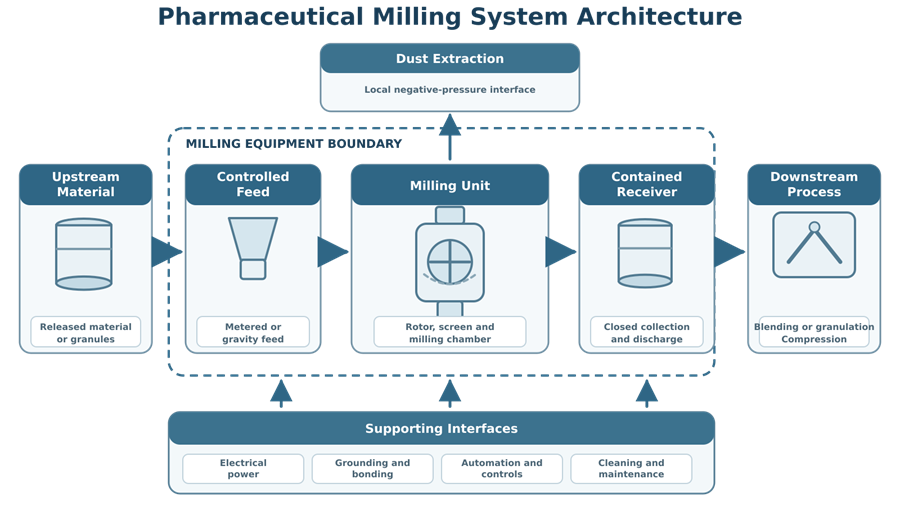
A typical material path may include:
Dispensing and material handling → feeding or transfer → milling or screening → collection or contained discharge → blending, granulation, compression, or encapsulation.
The approved process definition should identify:
- Why milling is required
- Material entering the mill
- Required output characteristics
- Upstream and downstream equipment
- Batch or continuous operating mode
- Acceptable hold and transfer conditions
- Required containment level
- Cleaning and product-changeover strategy
- Process parameters and material attributes requiring control
Particle-size-reduction mechanisms
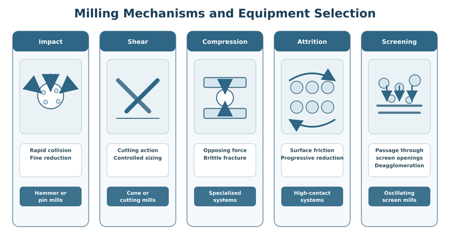
Pharmaceutical mills may apply one or more mechanical mechanisms. The dominant mechanism depends on the mill design, rotating element, screen, speed, material properties, and operating configuration.
Impact
Impact occurs when particles collide with rapidly moving hammers, pins, blades, or other internal components. Impact mills can provide substantial size reduction but may generate heat, fines, dust, and mechanical stress.
Shear
Shear cuts or tears material as particles pass between moving and stationary surfaces. Shear is often combined with impact in conical and comminuting mills.
Compression
Compression fractures particles between opposing surfaces. It may be used in specialized systems or occur as part of a combined milling mechanism.
Attrition
Attrition reduces particle size through friction between particles or between particles and equipment surfaces. Excessive attrition may increase fines and change powder behavior.
Screening and deagglomeration
Screening mills and low-energy sizing systems force material through defined openings to remove soft agglomerates or control oversized granules. The objective may be conditioning rather than aggressive particle-size reduction.
The mill should be selected based on the required function rather than on equipment name alone. Two mills described by similar terminology may have different rotor geometries, screens, operating ranges, heat generation, containment capability, and resulting particle-size distributions.
Common pharmaceutical mill configurations
Conical mills
Conical mills use a rotating impeller within a conical screen. Material is accelerated and forced through the screen openings.
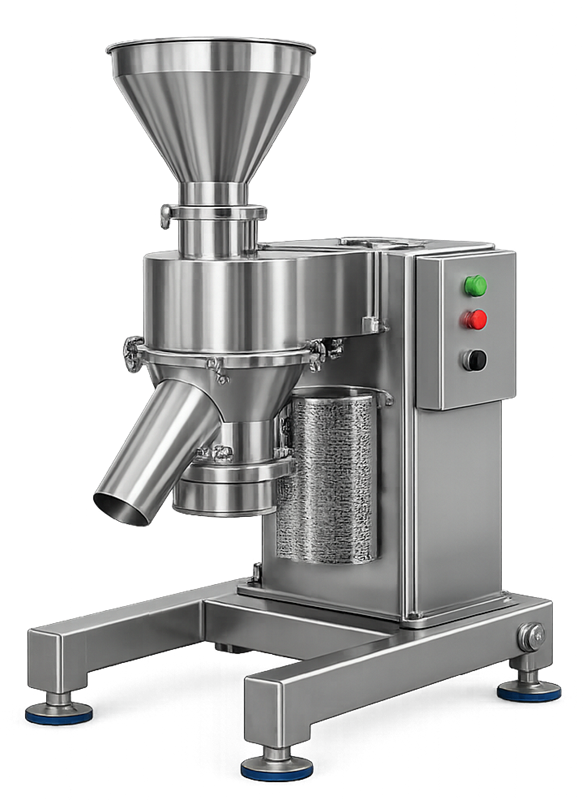
They are commonly used for:
- Delumping
- Dry-granule sizing
- Wet-mass sizing
- Controlled powder conditioning
- Transfer between containers and downstream equipment
Cone mills generally apply lower mechanical energy than high-speed impact mills, although actual performance depends on impeller design, speed, screen geometry, feed rate, and material properties.
Hammer mills
Hammer mills use rapidly moving hammers or blades to impact particles against internal surfaces and a retaining screen. They can achieve substantial size reduction and high throughput.
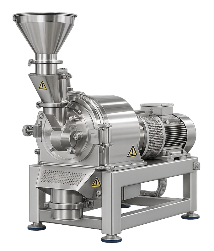
Potential concerns include:
- Generation of fines
- Product heating
- High noise and vibration
- Wear of hammers, screens, and internal surfaces
- Greater dust-generation potential
- Sensitivity to feed-rate variation
Pin mills
Pin mills use opposing or concentric arrangements of pins to create high-energy impact and particle-to-particle interaction. They may be used where relatively fine particle sizes are required.
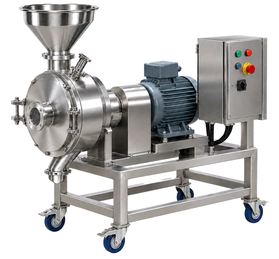
Important considerations include:
- Rotor speed
- Pin configuration and condition
- Temperature rise
- Material hardness and friability
- Potential for excessive fines
- Wear-particle risk
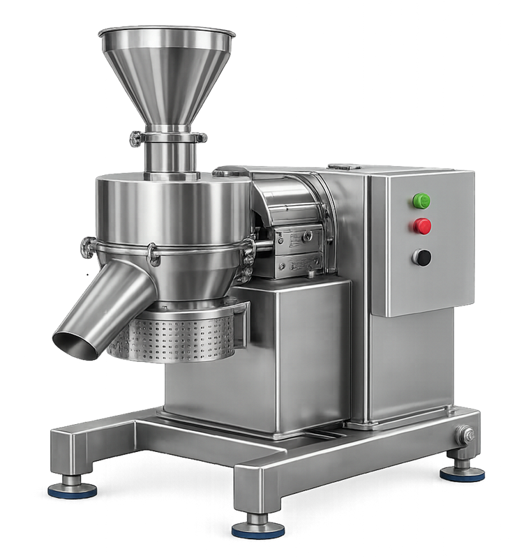
Comminuting mills
Comminuting mills use rotating blades or impellers with a screen to combine impact, cutting, and shear. Their performance depends strongly on blade orientation, speed, screen selection, clearance, and feed conditions.
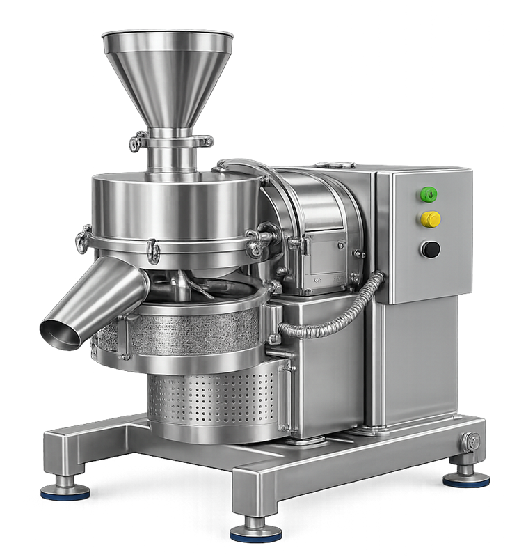
Screening and oscillating mills
Screening or oscillating mills are commonly used for gentle conditioning, removal of soft agglomerates, and sizing of granules. They may be appropriate when excessive impact, temperature rise, or fines generation must be avoided.
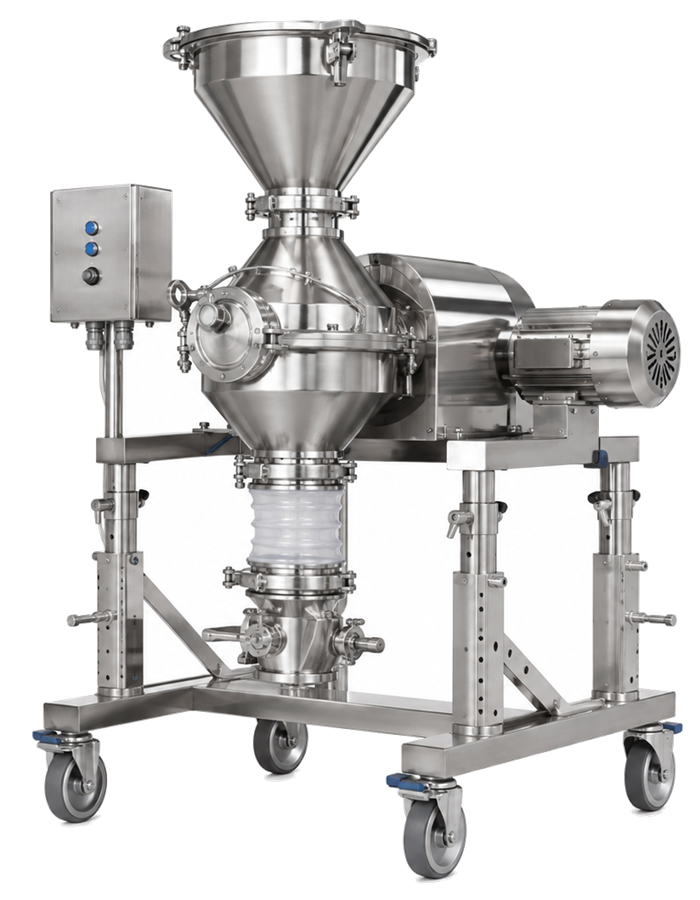
Integrated and mobile mills
Mills may be mounted:
- Beneath a dispensing container
- Between a granulator and dryer
- Beneath a fluid-bed processor
- Above a blender
- On a mobile frame
- Within an isolator or containment enclosure
- As part of a continuous manufacturing line
The mounting arrangement affects material flow, equipment boundaries, access, containment, cleaning, vibration transmission, and qualification scope.
Pharmaceutical mills differ substantially in internal geometry and milling intensity. The following illustration compares four common configurations and identifies the principal components responsible for material feeding, particle-size reduction, screening, and discharge.
Equipment design and critical components
Feed system
The feed system introduces material into the milling chamber. It may include:
- Gravity-fed hoppers
- Screw feeders
- Rotary valves
- Vibratory feeders
- Vacuum-transfer receivers
- Intermediate bulk containers
- Split butterfly valves
- Closed docking systems
An uncontrolled feed rate can overload the mill, increase temperature, change residence time, cause screen blinding, produce an inconsistent particle-size distribution, or trip the motor.
The design should prevent bridging, rat-holing, uncontrolled surging, contamination, and unintended material retention.
Milling chamber
The milling chamber contains the rotating assembly and directs material through the selected size-control component. Product-contact surfaces should be compatible with the material and cleaning agents and should not introduce contamination through corrosion, abrasion, lubricant migration, or retained residues.
The chamber should permit inspection of areas that could retain material or conceal damage.
Rotor, impeller, blades, hammers, or pins
The rotating assembly supplies mechanical energy to the material. Its geometry, orientation, speed, direction of rotation, clearance, and condition can influence milling performance.
Controls should prevent use of:
- Incorrect rotating assemblies
- Improper blade orientation
- Damaged or excessively worn components
- Unapproved replacement parts
- Incorrect rotation direction
- Improper assembly or inadequate fastening
Screens and sizing elements
Screen characteristics may include:
- Nominal opening size
- Opening geometry
- Open area
- Thickness
- Material of construction
- Surface finish
- Perforation pattern
- Supplier and part number
- Direction of installation
Screen condition is critical. Damage, distortion, enlarged openings, poor seating, or incorrect installation may permit oversized material to bypass the intended size-control function.
Screen identity and condition should be verified before use and inspected after processing when required by the approved procedure.
Discharge and collection system
The discharge system may deliver milled material to:
- A lined container
- Intermediate bulk container
- Blender
- Granulator
- Tablet press feed system
- Capsule-filling system
- Pneumatic transfer line
The design should minimize uncontrolled powder release, material retention, segregation, and incorrect routing. Flexible connections, liners, clamps, gaskets, and docking devices must be controlled as part of the equipment configuration.
Drive and mechanical support
The drive system commonly includes the motor, gearbox or direct drive, shaft, bearings, couplings, and structural support.
The design should address:
- Operating-speed range
- Motor capacity
- Overload protection
- Bearing condition
- Lubricant containment
- Alignment
- Vibration
- Noise
- Heat generation
- Access for maintenance
- Protection against rotating parts
Guards and safety interlocks
Access covers, chamber doors, and removable guards should be controlled by appropriate mechanical or electrical safeguards. Interlocks should prevent operation when access to hazardous moving parts is possible.
Emergency stops, overload protection, permissives, and safe restart behavior should be defined in the requirements and challenged during qualification.
Hygienic design and cleanability
Product-contact parts should be designed for effective cleaning, drying, inspection, assembly, and protection before use.
Design considerations include:
- Smooth and compatible product-contact surfaces
- Accessible joints and connections
- Minimized crevices and material traps
- Controlled gasket and seal design
- Drainability when wet cleaning is used
- Identification of removable product-contact parts
- Defined disassembly and reassembly
- Prevention of lubricant contact with product
- Protection of clean parts during storage
- Verification of equipment cleanliness before use
Milling components may contain difficult-to-clean features, including screen perforations, rotor recesses, shaft seals, blade fasteners, discharge transitions, flexible connectors, and dust-extraction branches.
Equipment design and qualified cleaning sequences support reproducible cleaning, but they do not replace the evidence required by the site’s cleaning-validation approach.
Where removable components are cleaned separately, the equipment boundary should identify the associated wash area, parts washer, manual-cleaning station, drying controls, inspection requirements, and clean-part storage arrangements.
Containment and dust control
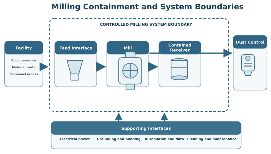
Milling can generate fine airborne particulate. The system may therefore require:
- Enclosed feeding and discharge
- Local extraction
- Negative pressure within the milling chamber
- Contained docking devices
- Disposable liners
- Isolator or glovebox integration
- High-containment valves
- Controlled filter changes
- Grounding and bonding
- Dust-tight flexible connections
- Defined cleaning and waste-removal methods
The extraction system must be balanced carefully. Insufficient airflow may allow dust release, while excessive airflow may remove product, change material flow through the mill, increase yield loss, or affect the particle-size distribution.
Detailed containment architecture, dust-collector design, filtration, safe waste handling, and performance verification are addressed in Pharmaceutical Powder Containment and Dust Collection Systems.
Combustible-dust and explosion-protection requirements must be established through a separate safety assessment based on the material, equipment, installation, and applicable codes. GMP qualification should verify the approved safety-related design and functions within its defined scope but should not replace the required process-safety assessment.
Critical operating parameters
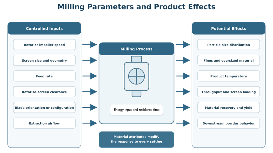
The importance of each parameter depends on the mill and product. A parameter should not be designated critical solely because the equipment can display or adjust it.
Rotor or impeller speed
Speed affects mechanical-energy input, impact frequency, shear, throughput, heat generation, and fines production. A higher speed does not always produce a more suitable output because excessive energy may damage the material or create an undesirable distribution.
Screen configuration
Screen opening size and geometry influence the maximum particle size and material residence within the milling chamber. Screen open area, thickness, condition, and installation may also affect throughput and heat generation.
Feed rate
Feed rate affects chamber loading and the energy applied per unit mass. Excessive feeding may overload the mill, blind the screen, increase retained material, or create an inconsistent output. Very low feeding may expose material to excessive energy and increase fines.
Rotor-to-screen clearance
Where adjustable or design-dependent, clearance influences shearing action, particle residence, equipment wear, and resulting particle size.
Blade or impeller orientation
Some mills permit alternative blade orientations or rotation directions. These configurations may produce different impact and cutting behavior and must be controlled as approved change parts or recipe settings.
Milling time or residence time
In batch or recirculating arrangements, processing time affects total energy exposure. In continuous systems, residence time is influenced by feed rate, chamber loading, rotor speed, and discharge behavior.
Product temperature
Mechanical energy can increase product temperature. Temperature monitoring may be required when material is heat-sensitive, has a low softening point, contains volatile components, or can undergo physical or chemical change.
Differential pressure or extraction airflow
Where dust extraction is integrated with the process, airflow or pressure may affect containment, product loss, and material movement. Applicable instruments, alarms, and operating limits should be defined.
Throughput
Throughput is an equipment-performance measure but may also affect particle-size distribution, temperature, material retention, and downstream scheduling. Rated capacity should not be treated as demonstrated process capability without testing under representative conditions.
Material attributes and process variability
Milling performance depends on more than equipment settings. Relevant material attributes may include:
- Initial particle-size distribution
- Agglomerate strength
- Moisture content
- Hardness
- Friability
- Elasticity or brittleness
- Density
- Shape
- Flowability
- Temperature
- Lubricity
- Electrostatic behavior
- Batch-to-batch variability
A mill may operate correctly while producing different results when the incoming material changes. Qualification of mechanical capability therefore cannot substitute for understanding the relationship between material attributes, operating parameters, and product quality.
Process development should determine which inputs and parameters require routine control. PPQ and continued process verification should then evaluate the integrated commercial process using qualified equipment. The distinction is further addressed in Process Qualification: Equipment Qualification and PPQ and General Principles of Process Validation.
Automation and control-system boundaries
A milling system may include:
- Local operator controls
- Variable-frequency drives
- Programmable logic controllers
- Human-machine interfaces
- Speed and feed-rate controls
- Motor-current or torque monitoring
- Temperature, vibration, pressure, or airflow instruments
- Alarm and interlock logic
- Recipe or configuration management
- Batch-system interfaces
- Electronic records
- Network connections
- Upstream and downstream permissives
The system boundary should identify which functions belong to the mill, feeder, dust collector, material-transfer system, facility automation, or manufacturing execution system.
Requirements should define:
- Authorized operating modes
- Adjustable parameters and permitted ranges
- Recipe selection and approval controls
- User-access levels
- Alarm setpoints and responses
- Interlock and permissive logic
- Data requiring retention
- Time synchronization
- Backup and recovery
- Handling of power loss and communication failure
- Restart and material-disposition requirements
Automation testing should be proportionate to GMP risk. A local speed display requires a different control strategy from an integrated recipe-driven system that records parameters, controls equipment sequencing, and creates electronic batch evidence.
User requirements and design qualification
The user requirements specification should define the intended milling function and measurable requirements for:
- Material and batch-size range
- Required milling or conditioning function
- Mill type and operating principle
- Throughput range
- Speed and feed-rate ranges
- Approved screens and change parts
- Product-contact materials and finishes
- Temperature limitations
- Containment and dust-control interfaces
- Cleaning and inspection
- Utility requirements
- Controls, alarms, interlocks, and data
- Ergonomic and safety features
- Calibration and maintenance access
- Upstream and downstream interfaces
- Documentation and traceability
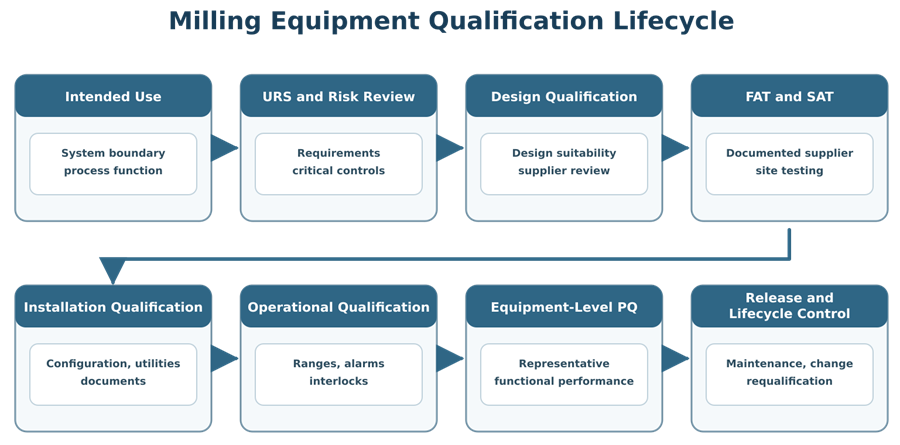
Design Qualification should verify that the proposed design can meet the approved requirements and address identified risks.
The review should consider:
- Suitability of the milling mechanism
- Equipment capacity and turndown
- Cleanability and disassembly
- Product-retention points
- Wear-component controls
- Containment strategy
- Dust-extraction effects
- Material-transfer arrangement
- Instrumentation and automation
- Component identification and error prevention
- Maintenance access
- Supplier documentation
- Testing planned for FAT, SAT, IQ, OQ, and PQ
Supplier documentation, FAT, and SAT
Supplier documentation may include:
- General arrangement and assembly drawings
- Product-contact material certificates
- Surface-finish information
- Motor and drive documentation
- Screen and rotor specifications
- Instrument data
- Electrical drawings
- Control-system descriptions
- Alarm and interlock matrices
- Software and configuration records
- Operating and maintenance manuals
- Recommended spare parts
- FAT results
- Calibration certificates
- Cleaning and assembly instructions
FAT may verify fabrication, component identity, controls, speed range, alarms, interlocks, direction of rotation, basic mechanical operation, and documentation before shipment.
SAT should confirm that the delivered mill remains complete and functional after installation. It may include equipment inspection, utility checks, rotation verification, controls testing, and interface checks.
Supplier testing may be incorporated into qualification when it has been reviewed, approved, traceable to requirements, and supplemented where necessary. Repeating an adequate test solely under a different document title does not improve assurance.
Installation Qualification
IQ should verify the installed configuration against approved requirements and design documents.
Typical IQ checks include:
- Manufacturer, model, serial number, and equipment identification
- Installed location and orientation
- Product-contact materials
- Surface-finish documentation where specified
- Rotor, blade, hammer, pin, and impeller identification
- Screen sizes and change-part inventory
- Drive, motor, and electrical characteristics
- Grounding and bonding
- Dust-extraction connections
- Feed and discharge interfaces
- Instrument and sensor identification
- Calibration status
- Guards and access controls
- Lubricants and potential product-contact risks
- Drawings, manuals, and spare-parts documentation
- Preventive-maintenance requirements
- Software and configuration identification
- Verification of utilities and environmental requirements
Discrepancies should be resolved or formally assessed before progression to affected operational testing.
Operational Qualification
OQ demonstrates that the mill and associated controls function correctly throughout the approved equipment operating range.
Testing may include:
- Start, stop, and emergency-stop functions
- Speed range and indication
- Feed-control range
- Direction of rotation
- Timer functions
- Motor-current, load, or torque indication
- Alarm setpoints and annunciation
- Guard and access-door interlocks
- Overload protection
- Permissives with feeders, transfer systems, and dust extraction
- Response to power loss
- Safe restart behavior
- Incorrect-component or assembly challenges where detectable
- Temperature, pressure, airflow, or vibration functions
- Recipe and user-access controls
- Electronic record generation where applicable
- Cleanability, assembly, and inspection procedures
- Operation using approved screen and rotor configurations
- Equipment behavior at defined lower and upper operating conditions
Challenges should verify expected equipment response, not merely confirm that a message appears on the operator interface.
Equipment-level Performance Qualification
Equipment-level PQ demonstrates that the installed mill can perform its intended equipment function under representative use conditions.
Depending on intended use, PQ may evaluate:
- Stable operation with representative materials
- Throughput capability
- Repeatability of controlled settings
- Material feeding and discharge
- Temperature rise
- Screen performance and integrity
- Material retention and recovery
- Containment performance
- Dust-extraction interaction
- Cleaning and changeover execution
- Coordination with upstream and downstream equipment
- Performance across representative batch sizes or material conditions
Particle-size data may be collected during equipment PQ when needed to demonstrate equipment capability. Product-specific acceptance criteria and reproducibility conclusions must remain aligned with process-development and process-validation responsibilities.
Successful equipment PQ supports readiness for PPQ but does not demonstrate that the complete commercial process consistently produces acceptable product. General equipment-level PQ principles are addressed in Performance Qualification for GMP Equipment and Systems.
Material recovery and yield reconciliation
Material recovery may be used to detect excessive retention, leakage, dust extraction loss, or transfer problems.
A simple recovery calculation is:
Recovery (%) = (Mass collected after milling ÷ Mass introduced into the milling system) × 100
The procedure should define:
- Included containers and liners
- Scale reconciliation
- Material remaining in the feeder, chamber, screen, discharge, and transfer path
- Material collected by the dust system
- Samples removed
- Spillage or documented losses
- Measurement uncertainty
- Treatment of retained or rejected material
A high recovery result does not prove that the particle-size distribution is acceptable. A mill may transfer most of the material while generating excessive fines, leaving oversized particles, or altering material characteristics.
Calibration and maintenance
Instruments used to control or make acceptance decisions should be included in the applicable calibration program and metrology control.
These may include:
- Speed indicators
- Feed-rate controls
- Timers
- Temperature sensors
- Pressure or differential-pressure instruments
- Airflow instruments
- Load cells
- Motor-current or torque measurements
- Vibration sensors
- Reference tachometers used during testing
Maintenance should address components subject to wear, damage, misalignment, or loss of performance, including:
- Screens
- Rotors and impellers
- Hammers, blades, and pins
- Bearings
- Seals and gaskets
- Shafts and couplings
- Drive belts
- Motors and gearboxes
- Flexible connectors
- Clamps and fasteners
- Dust-extraction components
- Safety interlocks
Replacement with a nominally equivalent component does not automatically eliminate qualification impact. Screen geometry, material, thickness, open area, rotor configuration, or supplier tolerances may affect performance.
Maintenance, inspection, post-maintenance testing, and return-to-service controls should follow the applicable preventive-maintenance and system-reliability strategy.
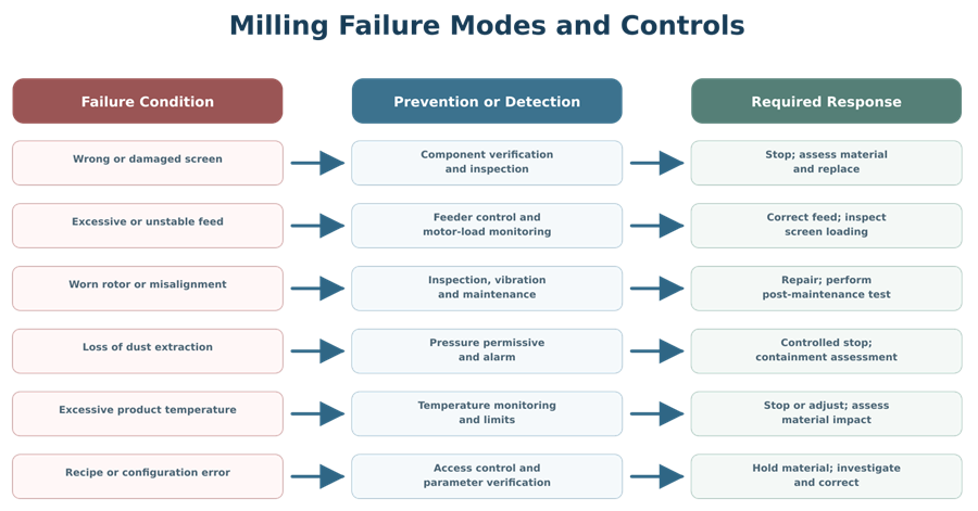
Common failure modes and controls
| Failure mode | Potential consequence | Typical controls |
|---|---|---|
| Incorrect screen installed | Incorrect particle-size distribution | Part identification, procedural verification, controlled storage |
| Damaged or poorly seated screen | Oversized particles or bypass | Pre-use and post-use inspection, assembly verification |
| Worn rotor, blade, hammer, or pin | Reduced or altered milling action | Defined inspection and replacement criteria |
| Excessive feed rate | Overload, heat, screen blinding, inconsistent output | Controlled feeder, motor-load monitoring, alarms |
| Inadequate feed rate | Excessive energy exposure and fines | Defined minimum range and feeder verification |
| Incorrect rotation or blade orientation | Changed milling mechanism | Assembly checks, direction verification, configuration control |
| Loss of dust extraction | Powder release and containment failure | Permissive, alarm, shutdown response |
| Excessive extraction airflow | Product loss or altered material flow | Qualified airflow range and balancing |
| Bearing or alignment deterioration | Vibration, heat, wear particles | Preventive maintenance and condition monitoring |
| Inadequate cleaning | Carryover or cross-contamination | Qualified cleaning procedure and cleaning validation |
| Control or recipe error | Operation outside approved conditions | Access control, recipe verification, audit trail where applicable |
| Power interruption | Uncertain material condition | Defined stop, restart, inspection, and disposition procedure |
Routine operation and continued control
Routine procedures should control:
- Equipment status and line clearance
- Product and batch identity
- Approved screen and change-part selection
- Correct assembly
- Pre-use cleanliness inspection
- Parameter entry or recipe selection
- Feed and discharge configuration
- Dust-extraction availability
- Grounding and bonding
- Start-up and shutdown
- In-process checks
- Screen inspection
- Material recovery
- Cleaning and changeover
- Deviation escalation
- Equipment release after maintenance
Operating data should be reviewed at a frequency appropriate to risk. Relevant trends may include:
- Throughput
- Milling time
- Motor load
- Temperature
- Screen failures
- Vibration
- Equipment alarms
- Material recovery
- Particle-size results
- Cleaning failures
- Maintenance frequency
- Unplanned downtime
- Deviations and rejected material
Adverse trends should be evaluated even when individual batches remain within acceptance criteria.
Change control and requalification
Changes requiring documented impact assessment may include:
- New product or material
- Revised intended use
- New batch-size range
- Different mill type or scale
- New screen size, geometry, material, or supplier
- Rotor, blade, hammer, pin, or impeller change
- Speed or feed-range modification
- Drive or motor replacement
- Feeder or discharge modification
- Dust-extraction or containment change
- New liner, gasket, seal, or flexible connector
- Control-system, recipe, software, or alarm change
- Relocation
- Cleaning-procedure change
- Major repair
- Repeated mechanical failure
- Extended shutdown
- Adverse performance trend
Requalification should be based on the affected requirements, risks, functions, interfaces, and evidence. The response may range from a documented assessment with limited verification to targeted OQ or PQ, cleaning revalidation, containment testing, or comprehensive requalification.
A calendar date alone should not determine test scope. However, periodic activities required by approved procedures, applicable standards, safety programs, or the site control strategy must still be performed.
Documentation and traceability
The lifecycle record should connect:
- Intended use
- System boundaries
- User requirements
- Risk assessments
- Design decisions
- Supplier documentation
- FAT and SAT evidence
- DQ, IQ, OQ, and equipment-level PQ
- Approved components and change parts
- Calibration and maintenance requirements
- Cleaning procedures
- Operating procedures
- Training
- Deviations and corrective actions
- Release decisions
- Change controls
- Requalification
- Periodic review
- Retirement or replacement
Traceability should demonstrate that each critical requirement and identified risk has been addressed by design, procedural control, testing, monitoring, or another justified control.
Regulatory basis
Milling equipment used in drug-product manufacturing is subject to the applicable equipment requirements of 21 CFR Part 211. Equipment must be appropriately designed, sized, located, constructed, cleaned, maintained, and controlled for its intended use. Automatic, mechanical, and electronic equipment must be routinely calibrated, inspected, or checked under a written program designed to assure proper performance. See 21 CFR Part 211, Subpart D—Equipment.
FDA’s process-validation lifecycle distinguishes qualification of facilities, utilities, and equipment from PPQ of the integrated commercial manufacturing process. See Process Validation: General Principles and Practices.
Conclusion
Pharmaceutical milling equipment must be selected, designed, qualified, operated, cleaned, and maintained according to its intended function and the risks associated with the material and process.
A defensible control strategy addresses the complete milling system: feeding, milling components, screens, discharge, containment, dust extraction, automation, utilities, cleaning, calibration, maintenance, and downstream interfaces.
Equipment qualification establishes that the mill is properly installed and capable of controlled operation under representative conditions. Product-specific process development, PPQ, and continued process verification are still required to demonstrate that milling supports reproducible commercial manufacturing and acceptable product quality.