

Sanitary Design of Pharmaceutical Tanks and Process Vessels
Pharmaceutical tanks and process vessels must do more than contain material. Their design must support the intended process, protect product quality, control contamination, enable cleaning or sterilization, withstand defined operating conditions, and integrate reliably with instruments, automation, utilities, and downstream equipment.
The design basis must address the complete operating lifecycle. Conditions during charging, mixing, heating, cooling, transfer, sampling, cleaning, steam exposure, draining, shutdown, and maintenance may impose different demands on the vessel. A tank designed only around its normal production condition can fail when exposed to vacuum during draining, thermal stress during cleaning, condensate accumulation during steam-in-place, or low-level mixing outside the effective impeller range.
This article addresses sanitary and functional design requirements for fixed and portable pharmaceutical tanks and process vessels. Vessel functions and material categories are discussed in Pharmaceutical Tank and Process Vessel Types, Functions, and Materials. Qualification execution is covered in Tank and Process Vessel Qualification and Lifecycle Control, while equipment-side cleaning requirements are addressed in Tank and Process Vessel Cleaning and CIP Integration.
Regulatory and Engineering Basis
Under 21 CFR 211.63—Equipment Design, Size, and Location, manufacturing equipment must be appropriately designed, adequately sized, and suitably located for its intended use, cleaning, and maintenance. 21 CFR 211.65—Equipment Construction requires product-contact surfaces to be nonreactive, nonadditive, and nonabsorptive to the extent necessary to protect product quality.
These requirements do not prescribe one universal vessel geometry, surface finish, material, or connection standard. The manufacturer must establish requirements appropriate to the product, process, cleaning method, hygienic state, and operating environment.
The ASME BPE—Bioprocessing Equipment standard provides an important engineering framework for hygienic equipment, including materials, design, fabrication, surface condition, examination, inspection, and testing. Applicable requirements should be identified in the project specifications. General reference to “ASME BPE construction” is not sufficiently precise unless the applicable edition, sections, service conditions, and acceptance requirements are defined.
Pressure-vessel codes, electrical standards, occupational-safety requirements, building codes, and site engineering standards may also apply. Mechanical-code compliance and pharmaceutical hygienic suitability are related but separate design obligations.
Intended Use and User Requirements
Sanitary design begins with a defined intended use. The user requirements specification should describe what the vessel must accomplish and the conditions under which it must operate.
Requirements should address, as applicable:
- Materials processed and their relevant physical, chemical, and biological characteristics
- Batch size, working volume, minimum operating volume, and total vessel volume
- Required mixing, dissolution, suspension, emulsification, or reaction performance
- Product-contact and hold durations
- Temperature range and required heating or cooling performance
- Normal operating pressure and vacuum
- Credible abnormal pressure and vacuum conditions
- Open, closed, sterile, inerted, or contained operation
- Ingredient-charging and sampling methods
- Required transfer rates and discharge conditions
- Product recovery and allowable retained volume
- Cleaning, sanitization, or sterilization methods
- Utility and process-system interfaces
- Instrumentation, automation, alarm, and electronic-record requirements
- Access for operation, inspection, maintenance, and calibration
- Area-classification and environmental requirements
- Operator and environmental containment needs
- Required documentation, testing, certification, and supplier support
Requirements should distinguish fixed process needs from engineering preferences. A required maximum heat-up time, for example, is a functional requirement. A specified jacket type is a design solution and should not be imposed unless supported by process knowledge, site standardization, or another justified constraint.
The approved requirements provide the basis for design review, supplier selection, qualification planning, and lifecycle change assessment.
System Boundary and Interfaces
A vessel should be defined as a system rather than as an isolated shell. The equipment boundary may include:
- Vessel shell, heads, supports, and insulation
- Agitator drive, shaft, impellers, baffles, and mechanical seal
- Heating or cooling jacket and associated controls
- Product inlets and outlets
- Addition ports, dip tubes, and spargers
- Sampling devices
- Vent filter and pressure-control assembly
- Spray devices and CIP connections
- SIP supply, vent, and condensate paths
- Product-contact valves, gaskets, diaphragms, and seals
- Temperature, pressure, level, weight, pH, conductivity, or other instruments
- Local control panel, programmable controller, and operator interface
- Transfer pumps or recirculation loops
- Safety devices and emergency controls
- Defined connection points to facility utilities and other process systems
Boundary drawings should distinguish product-contact, indirect product-contact, utility, automation, structural, and safety functions. They should also identify which components belong to the vessel supplier and which belong to facility piping, automation, or another equipment package.
Undefined interfaces frequently create qualification gaps. A vessel supplier may consider the CIP connection to be the limit of supply, while the site assumes that spray-device performance has been demonstrated as part of the vessel package. The interface and responsible party must be explicit.
Sanitary Geometry and Cleanability
Vessel geometry should minimize areas where product, cleaning solution, rinse water, or condensate can remain after the applicable operation. The required degree of sanitary control depends on intended use, but the design should address:
- Internal surface continuity
- Drainage toward defined low points
- Product and cleaning-solution hold-up
- Crevices and narrow gaps
- Shadowing created by internal components
- Nozzle and branch orientation
- Agitator and baffle geometry
- Manway and head configuration
- Spray-device location
- Accessibility for inspection
- Required cleanability or sterilizability
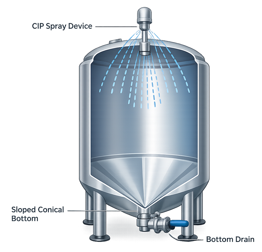
A sanitary vessel is not defined only by a conical bottom or polished finish. Poorly located probes, long dip tubes, recessed gaskets, non-drainable sample valves, obstructed spray patterns, and retained liquid in outlet assemblies can defeat an otherwise acceptable shell design.
Vessel Heads and Bottom Geometry
Dished, hemispherical, torispherical, sloped, or conical heads may be used depending on mechanical and process requirements. Bottom geometry should direct liquid toward the intended outlet without creating isolated low points.
Selection should consider:
- Material viscosity and flow behavior
- Solids content and settling tendency
- Required product recovery
- Agitator clearance
- Spray coverage
- Access for inspection
- Mechanical loading
- Pressure or vacuum rating
- Jacket configuration
- Required drainage endpoint
“Fully drainable” should not be treated as an assumed characteristic. Drainability depends on the installed vessel level, bottom geometry, outlet and valve construction, internal attachments, surface condition, fluid properties, and operating sequence. Where drainage is important, the requirement should be measurable and verified under defined conditions.
Dead Legs, Branches, and Nozzles
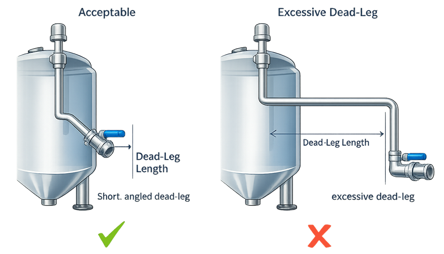
Branches connected to the vessel should be kept as short and direct as practical for the intended hygienic service. Potential problem areas include:
- Instrument branches
- Sample-valve connections
- Unused or capped nozzles
- Long inlet branches
- Vent and filter connections
- Pressure-gauge branches
- Chemical-addition connections
- CIP and SIP connections
- Spare ports retained for possible future use
A simple branch-length-to-diameter ratio does not by itself establish acceptable design. Orientation, flow pattern, cleaning method, thermal exposure, branch geometry, valve location, and intended hygienic state also matter.
Unused connections should not remain merely because they were included in a standard supplier design. Each port should have a defined function or a justified closure arrangement that remains cleanable, drainable, and inspectable.
Vessel Geometry and Structural Design
The vessel must be mechanically suitable for every defined operating and lifecycle condition. Relevant loads may arise from:
- Liquid and product weight
- Agitator torque and vibration
- Internal pressure
- External pressure or vacuum
- Jacket pressure
- Thermal expansion and contraction
- Steam exposure and condensate formation
- Seismic or wind loading where applicable
- Connected piping loads
- Operator access platforms
- Insulation and cladding
- Transport or movement of portable vessels
- Lifting, weighing, or load-cell arrangements
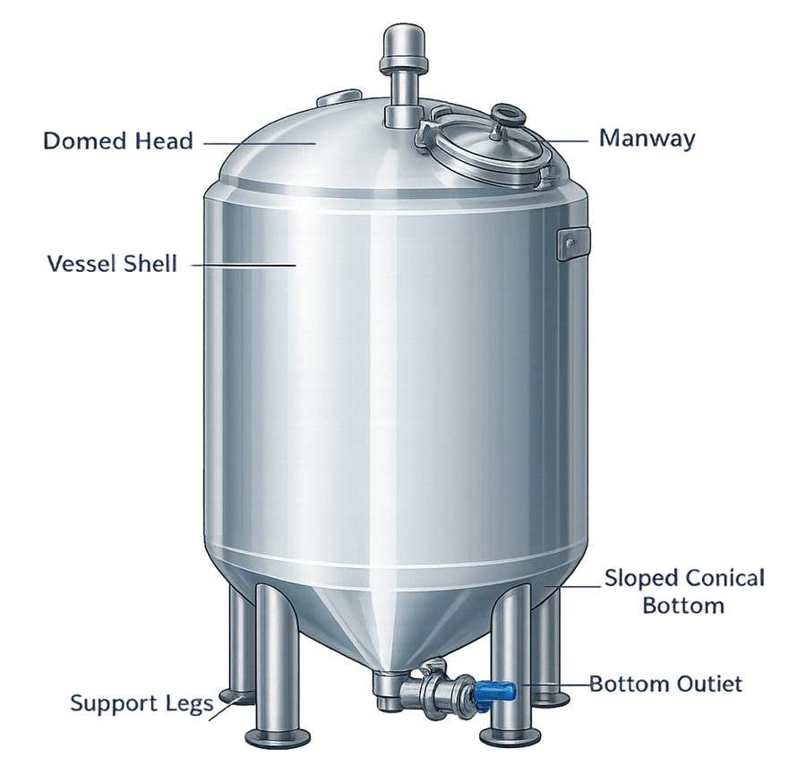
The relationship between vessel height and diameter affects mixing, heat transfer, room fit, access, and cleanability. A tall, narrow vessel may provide different mixing and thermal behavior from a short, wide vessel of equal volume.
Support legs, skirts, frames, lifting points, and load-cell assemblies should maintain mechanical stability without compromising drainage or introducing unacceptable stress. Adjustable supports may be necessary to establish the installed slope or vessel level required by the design.
Manways and access openings should permit necessary inspection and maintenance while preserving the required pressure rating and hygienic boundary. Their location should account for operator access, gasket inspection, safe opening, internal-component removal, and prevention of external contamination entering the vessel.
Materials and Product-Contact Surface Condition
The material-selection basis should address the product, intermediates, cleaning agents, sanitization chemicals, steam, process gases, temperature, pressure, exposure duration, and repeated lifecycle conditions.
The complete product-contact boundary includes more than the vessel shell. It may contain:
- Base metal and weld filler
- Gaskets and O-rings
- Valve diaphragms
- Mechanical-seal materials
- Instrument seals
- Sight-glass components
- Spray devices
- Filters
- Hoses and flexible connections
- Polymer tubing and disposable components
- Lubricants at credible failure interfaces
Material grade, surface treatment, and supplier documentation should be specified according to intended use. A general statement such as “316L stainless-steel construction” does not define weld quality, surface roughness, passivation, electropolishing, ferrite control, material traceability, or nonmetallic product-contact components.
Surface Finish
Internal surface-finish requirements should be based on product characteristics, cleaning method, microbial-control needs, and applicable standards. The specification should identify:
- Required surface-finish designation
- Maximum roughness where applicable
- Whether requirements apply to base material, welds, or both
- Mechanical polishing requirements
- Electropolishing where required
- Treatment of weld discoloration and heat-affected zones
- Permitted defects and repair methods
- Measurement method and sampling locations
- Required records and traceability
A surface-roughness value alone does not demonstrate hygienic suitability. Pits, laps, inclusions, cracks, crevices, poorly blended welds, and embedded contamination may be unacceptable even when an isolated roughness measurement meets its numerical limit.
Welds and Fabrication
Fabrication specifications should define:
- Welding process and procedure requirements
- Welder or operator qualifications
- Weld-filler requirements
- Shielding and purge-gas controls
- Weld identification and traceability
- Visual inspection criteria
- Borescope inspection where applicable
- Nondestructive examination where required
- Treatment of weld discoloration
- Repair authorization and documentation
- Final cleaning and surface treatment
Weld maps should identify relevant product-contact and pressure-boundary welds and connect them to inspection and repair records. Supplier documentation should distinguish original welds from repaired welds rather than presenting only a final summary.
Passivation or electropolishing should be controlled processes with defined procedures, chemicals, exposure conditions, rinsing, acceptance, and records. These treatments do not correct unacceptable weld geometry or fabrication defects.
Agitation and Mixing Design
Agitation design must be based on the required process outcome. Possible objectives include:
- Powder wetting and dissolution
- Concentration uniformity
- Temperature uniformity
- Solids suspension
- Prevention of settling
- Gas dispersion
- Emulsion formation or maintenance
- Heat-transfer enhancement
- Gentle product movement during holding
Relevant design variables include:
- Vessel diameter and liquid height
- Minimum and maximum working volume
- Impeller type, diameter, and position
- Number of impellers
- Rotational-speed range
- Motor power and gearbox capacity
- Baffle number, size, and position
- Product viscosity and density
- Solids content and particle behavior
- Permitted shear
- Vortex formation and air entrainment
- Surface foaming
- Heat generation
- Shaft critical speed and vibration
- Mechanical-seal configuration
- Required direction of rotation
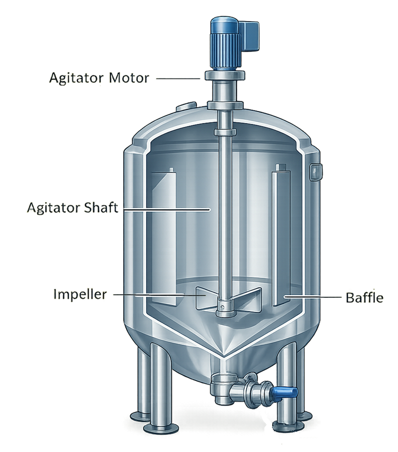
A mixer should not be sized only for maximum batch volume. Low-volume operation can expose an impeller, reduce circulation, draw air into the product, or place instruments outside the mixed region. The qualified operating range must be supported by the physical configuration.
Variable-speed control, acceleration, deceleration, and direction should be defined where they affect product quality or equipment protection. Interlocks may be needed to prevent operation below minimum liquid level, above an approved speed, with an open manway, or under an incompatible process condition.
Bottom-mounted magnetic mixers can reduce shaft penetration through the vessel head but introduce their own clearance, bearing, coupling, maintenance, and low-volume considerations. No mixer arrangement is universally superior.
Heating, Cooling, and Thermal Control
Temperature-controlled vessels may use external jackets, half-pipe coils, dimple jackets, internal coils, external recirculation heat exchangers, electrical heating, or combinations of these methods.
The design should establish:
- Required heating and cooling rates
- Target temperature range
- Allowable temperature overshoot
- Required temperature uniformity
- Utility supply and return conditions
- Available heat-transfer area
- Product viscosity and heat-transfer properties
- Agitation dependency
- Minimum and maximum batch volumes
- Jacket pressure and temperature ratings
- Thermal-fluid compatibility
- Condensate removal where steam is used
- High- and low-temperature protection
- Leakage detection or failure assessment
Internal coils provide additional heat-transfer area but add product-contact surfaces, supports, joints, shadowed regions, and potential cleaning restrictions. External jackets avoid internal obstructions but may have limited performance depending on vessel size, utility conditions, and product behavior.
The vessel and jacket are separate pressure boundaries. Their allowable pressures, protective devices, and credible leakage consequences should be independently evaluated. Pressure relationships should prevent a jacket-side failure from introducing unacceptable thermal fluid into the product-contact space where reasonably achievable.
Temperature-sensor location should represent the process condition to be controlled. A sensor near the jacket wall, outlet, or stagnant region may not represent the bulk material temperature.
Instrumentation and Process Connections
Instrumentation should be selected and located according to the measurement objective, operating range, cleaning method, calibration needs, and failure consequences.
Typical vessel instruments include:
- Product temperature sensors
- Jacket supply and return temperature sensors
- Pressure or vacuum transmitters
- Local pressure gauges
- Level instruments
- Load cells
- Agitator-speed feedback
- pH, conductivity, or dissolved-oxygen probes
- Flow instruments on additions or transfer paths
- Valve-position feedback
- Vent-filter differential-pressure monitoring
Each instrument should have a defined range, accuracy, materials of construction, process connection, hygienic orientation, calibration strategy, and removal method. Instrument branches and protective wells should not create unacceptable hold-up or prevent cleaning.
Redundant or independent instruments may be justified where one measurement performs both process-control and safety functions, where a sensor failure could remain undetected, or where the process consequence is significant.
Level and Weight Measurement
Level may be measured by load cells, pressure-based instruments, radar, capacitance, sight glasses, or other technologies. Selection should account for:
- Vessel geometry
- Foam and agitation
- Product density
- Pressure or vacuum
- Temperature
- Minimum measurable volume
- Cleanability
- Calibration method
- Connected piping forces
- Portable-vessel movement
Load-cell systems require flexible connections or other arrangements that prevent piping loads from corrupting the measurement. Maintenance work, hose connections, insulation, platforms, and debris around supports can also affect accuracy.
Sampling Systems
Sampling design should provide a representative sample without creating unacceptable contamination, exposure, or retained-material risks. The sample location and method should address:
- Required process stage
- Mixing condition
- Vessel volume
- Potential stratification
- Sample-line volume
- Flushing or purge requirements
- Operator exposure
- Environmental exposure
- Cleaning or sterilization
- Drainability
- Sample-valve maintenance
A sanitary sample valve does not by itself demonstrate sample representativeness. Sample-point selection must be linked to process behavior and the intended analytical result.
Addition and Transfer Connections
Ingredient-addition ports should support the actual charging method. Open powder charging, closed transfer, liquid addition, sterile connection, vacuum transfer, and contained docking impose different requirements.
Transfer design should consider:
- Pump type and capacity
- Gravity or pressure transfer
- Nitrogen-assisted transfer
- Outlet location
- Vortex and air entrainment
- Minimum recoverable volume
- Hose or hard-pipe connections
- Route verification
- Drainage after transfer
- Prevention of reverse flow
- Containment and spill control
Venting and Headspace Control
Every vessel requires a defined means of managing displaced gas during filling, draining, heating, cooling, mixing, and cleaning. Depending on intended use, the vent system may include:
- Open or screened atmospheric venting
- Hydrophobic vent filtration
- Heated vent-filter housing
- Nitrogen or other gas overlay
- Pressure-control valve
- Vacuum protection
- Condenser or vapor-recovery equipment
- Scrubber or contained exhaust
- Oxygen or moisture control
- Differential-pressure monitoring
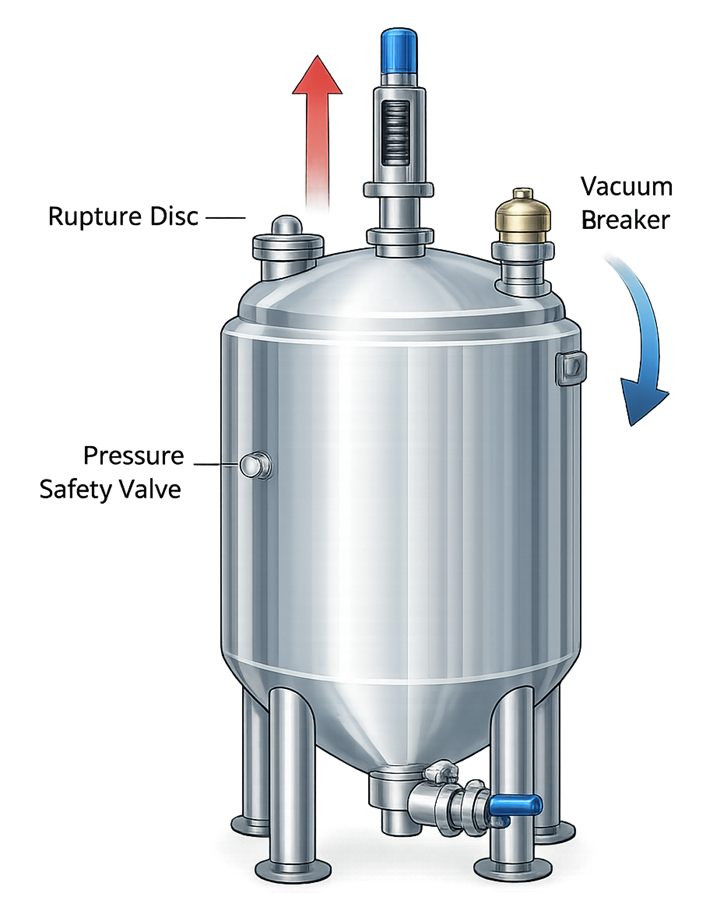
Vent capacity must represent credible filling, draining, steam-condensation, gas-addition, and thermal-transient rates. A vent sized only for normal production filling may be inadequate during rapid pump-out, cooling, or steam collapse.
Where a sterile vent filter forms part of the sterile boundary, the design should address filter compatibility, sterilization, integrity testing, condensate management, installation orientation, replacement, and protection against wet blockage. A sterile filter can become a source of excessive pressure or vacuum if it is wetted, fouled, frozen, or incorrectly isolated.
Pressure and Vacuum Protection
A vessel may be exposed to pressure or vacuum during:
- Gas blanketing
- Pressure transfer
- Heating or cooling
- Product filling or draining
- Pump-out
- CIP circulation
- Steam-in-place
- Steam condensation
- Blocked or isolated vent conditions
- Control-valve failure
- Regulator failure
- Incorrect valve sequencing
The design basis should define maximum allowable working pressure, design pressure, design temperature, vacuum rating, jacket rating, and applicable code requirements.
Pressure-relief devices, rupture disks, vacuum breakers, regulators, and control valves should be selected for credible scenarios. Their capacity, setpoint, location, discharge path, materials, cleanability, inspection, and maintenance requirements should be documented.
Protection devices should not create an unassessed contamination path. Where a relief device communicates with the product-contact space, the design must address hygienic construction, drainage, cleaning, sterilization, and post-activation disposition.
Control-system alarms and interlocks provide important protection but should not be assumed to replace an independently required mechanical protective device.
Utility Integration
A process vessel may interface with:
- Purified water or Water for Injection
- Clean steam
- Plant steam
- Heating or cooling water
- Glycol or another thermal fluid
- Compressed air
- Nitrogen or other process gases
- Clean-in-place supply and return
- Steam-in-place supply, vent, and condensate return
- Electrical power
- Instrument air
- Vacuum
- Drain, recovery, or neutralization systems
Each connection should have a defined purpose, quality requirement, pressure and temperature range, capacity, isolation method, backflow control, drainage provision, and ownership boundary.
Utility design must account for simultaneous demand. A jacket, CIP circuit, or SIP cycle that performs adequately when tested alone may not meet its requirement when multiple users operate concurrently. Capacity studies should represent the intended production schedule and credible demand combinations.
CIP Integration
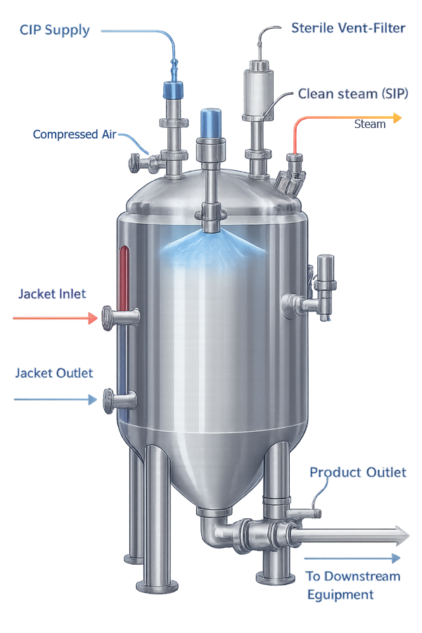
The vessel design should define the cleaning circuit rather than merely provide a CIP inlet. Equipment-side requirements include:
- Spray-device type and location
- Required flow and pressure range
- Supply and return connection sizes
- Exposure of agitators, baffles, probes, dip tubes, and vessel-head surfaces
- Control of spray shadows
- Cleaning of valves, seats, gaskets, and sample paths
- Return restriction and backpressure
- Drainage after each cleaning phase
- Safe equipment configuration during cleaning
- Prevention of product and cleaning-fluid path overlap
The broader utility architecture is addressed in Clean-in-Place (CIP) Utility Systems. Equipment-specific coverage, drainage, sampling, and cleaning-validation interfaces are addressed in Tank and Process Vessel Cleaning and CIP Integration.
SIP Integration
A vessel intended for steam-in-place must be designed as part of an integrated sterilization boundary. The design should support:
- Air removal
- Steam contact with required internal surfaces
- Venting at appropriate locations
- Condensate removal from low points
- Drainable instrument and valve branches
- Suitable gasket and seal materials
- Temperature-sensor installation
- Sterile vent-filter sterilization
- Controlled cooling and pressure management
- Maintenance of the post-cycle sterile boundary
Steam supply pressure alone does not demonstrate sterilization capability. Geometry, air removal, condensate drainage, saturated-steam conditions, cold locations, and exposure time collectively affect performance. These requirements are addressed in Steam-in-Place (SIP) Utility Systems.
Automation and Control Design
Automated vessels may include a programmable logic controller, local operator interface, supervisory control system, recipe management, historian, electronic batch-record interface, or manufacturing-execution-system connection.
The functional design should address:
- Operating modes and state transitions
- Recipe selection and version control
- Agitator control
- Heating and cooling sequences
- Ingredient additions
- Level- or weight-based control
- Transfer and discharge sequences
- CIP and SIP permissives
- Valve-position verification
- Alarm generation and response
- Manual operations and overrides
- Equipment and personnel safety interlocks
- Power-loss and restart behavior
- Communication failure
- Instrument failure
- Data recording and reporting
- User roles and access restrictions
- Backup and restoration
- Configuration management
Operating sequences should distinguish permissives, interlocks, alarms, warnings, and cycle-failure conditions. An alarm informs the operator; an interlock prevents or terminates an action. The design should not rely on operator response where automatic prevention is required by the risk assessment.
Manual mode, maintenance mode, forced outputs, bypassed interlocks, and engineering access can defeat the approved control strategy. Their authorization, visibility, recording, restoration, and post-use assessment should be defined.
Where electronic records support batch acceptance, cleaning-cycle disposition, sterilization-cycle disposition, or another GMP decision, the record content and data flow should be established during design rather than added after automation development.
Maintainability, Inspection, and Calibration Access
A hygienic design must remain maintainable throughout its lifecycle. Components requiring routine inspection, calibration, replacement, or repair should be accessible without uncontrolled disassembly or damage to adjacent systems.
Design review should address:
- Removal of agitator drives, shafts, impellers, and seals
- Access to manways and internal surfaces
- Removal and calibration of instruments
- Replacement of vent filters
- Inspection and testing of protective devices
- Gasket and diaphragm replacement
- Spray-device inspection
- Jacket and insulation inspection
- Drain and low-point access
- Safe isolation of electrical, pneumatic, hydraulic, thermal, and pressure energy
- Space for lifting equipment and maintenance tools
- Restoration of hygienic status after maintenance
Components hidden by insulation or cladding may require inspection ports, removable sections, leak-detection provisions, or defined examination methods. Maintenance access should not require uncontrolled standing on piping, instruments, or vessel surfaces.
Portable vessels require additional consideration of wheels, brakes, frames, handles, lifting points, flexible connections, impact protection, and storage conditions.
Design Documentation
The design package should provide sufficient evidence to define, review, install, qualify, operate, and maintain the vessel. Depending on complexity and risk, documentation may include:
- Approved user requirements specification
- Process description and intended-use statement
- System-boundary drawing
- Process and instrumentation diagrams
- General arrangement drawings
- Vessel fabrication drawings
- Nozzle and orientation drawings
- Agitator and mixer calculations
- Heat-transfer calculations
- Pressure and vacuum design calculations
- Relief-device sizing
- Utility-consumption data
- Control philosophy
- Functional and software specifications
- Instrument and alarm lists
- Valve and component lists
- Materials-of-construction schedule
- Surface-finish specification
- Welding procedures and qualification records
- Material certificates and traceability records
- Weld maps and inspection results
- Passivation or electropolishing records
- Pressure-test documentation
- Mechanical-code documentation
- Operating and maintenance manuals
- Recommended spare-parts list
- Calibration requirements
- Supplier software and configuration records
The required documentation should be identified before fabrication. Attempting to reconstruct material traceability, weld records, surface-treatment evidence, or software baselines after delivery creates avoidable qualification deficiencies.
Design Review and Qualification Readiness
Design review should be performed by personnel representing process engineering, manufacturing, validation, quality, automation, maintenance, safety, and other affected functions. The review should verify that requirements have been translated into a coherent, testable design.
The review should assess:
- Requirement coverage and unresolved assumptions
- Product-contact boundary
- Materials and compatibility
- Surface and weld requirements
- Cleanability and drainability
- Mixing and thermal performance
- Minimum and maximum operating volumes
- Pressure, vacuum, and protective devices
- Instrument ranges and locations
- Sampling and transfer configuration
- CIP and SIP interfaces
- Automation, alarms, and failure response
- Utility capacity and operating conditions
- Maintenance and calibration access
- Supplier-documentation commitments
- Qualification testability
- Open technical risks and required studies
Design qualification or an equivalent documented design review should show how the approved design satisfies the intended use and user requirements. It should not merely confirm that drawings exist or that a supplier follows a recognized standard.
Factory testing can verify fabrication, controls, instrumentation, agitation, pressure integrity, documentation, and other supplier-accessible functions before shipment. Site testing should then confirm the installed configuration, facility interfaces, utilities, automation integration, and functions that cannot be represented adequately at the supplier.
Detailed qualification strategy and lifecycle control are addressed in Tank and Process Vessel Qualification and Lifecycle Control. FDA’s Process Validation: General Principles and Practices places equipment design and qualification within the broader process-validation lifecycle.
Lifecycle Design Considerations
The original design should support future control of:
- Product or process changes
- Expanded operating ranges
- New cleaning agents or cycles
- Instrument replacement
- Automation and recipe changes
- Agitator or seal replacement
- Vent-filter changes
- Gasket and elastomer changes
- Welding or surface repairs
- Utility changes
- Supplier obsolescence
- Changes to connected equipment
- Inspection findings and recurring failures
Baseline drawings, specifications, software versions, instrument ranges, alarm settings, materials, and component identities should be maintained under change control. The validated state depends on the current installed configuration, not only on the original qualification package.
Conclusion
Effective pharmaceutical vessel design integrates process performance, hygienic construction, mechanical integrity, cleaning, sterilization, instrumentation, automation, utilities, safety, and lifecycle maintenance within one defined system boundary.
No isolated design feature establishes suitability. Stainless-steel construction, a polished surface, sanitary fittings, a spray ball, or an ASME designation can support an acceptable design, but each must be evaluated within the complete intended use.
A requirements-based design and documented multidisciplinary review provide the foundation for efficient fabrication, defensible qualification, effective cleaning integration, reliable manufacturing performance, and controlled lifecycle operation.