

Bioreactor and Fermenter Design, Functionality, and Process Control
Purpose and scope
Bioreactors and fermenters provide a controlled environment for the growth, metabolism, and production activity of cells or microorganisms. Their design must support the biological process while maintaining the required mixing, mass transfer, temperature, pressure, containment, sterility, addition, sampling, and harvest conditions.
This article addresses the engineering architecture and functional control of stainless-steel and single-use bioreactors used in pharmaceutical and biopharmaceutical manufacturing. It covers equipment design, operating modes, process parameters, control strategies, scale considerations, and major failure conditions.
Detailed bioreactor instrumentation and sensor integration and bioreactor qualification are addressed separately. Product-specific process development, Process Performance Qualification, and Continued Process Verification remain part of the process validation lifecycle.
A production bioreactor integrates mechanical equipment, process piping, utilities, instrumentation, and automated controls into one processing system. The configuration below illustrates the principal external features of a stainless-steel bioreactor used in a controlled manufacturing environment.
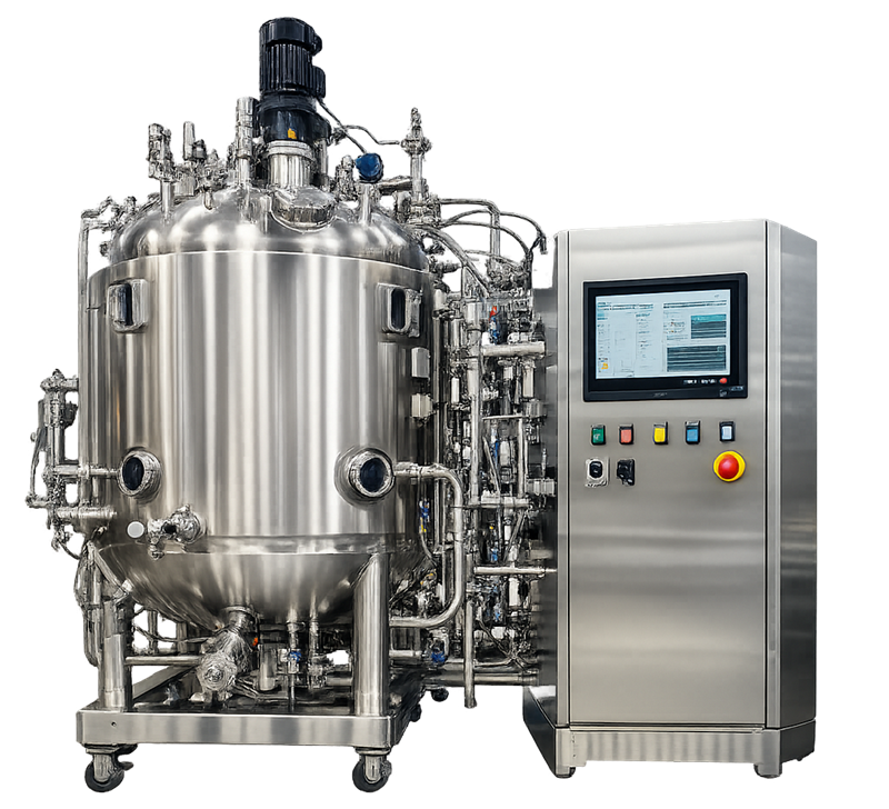
Bioreactors and fermenters
The terms bioreactor and fermenter are sometimes used interchangeably, but usage commonly reflects the biological process:
- Bioreactor is the broader term for a controlled vessel supporting cells, microorganisms, enzymes, or other biological systems.
- Fermenter is commonly associated with microbial processes involving bacteria, yeast, or fungi.
- Cell-culture bioreactor generally refers to systems supporting mammalian, insect, plant, or other shear-sensitive cells.
The terminology does not determine the GMP control strategy. Requirements must be based on the actual organism, process, product, operating mode, equipment configuration, and potential effect on product quality.
A production bioreactor will normally be considered a direct-impact system when its operating conditions can affect cell growth, product formation, impurity profiles, yield, contamination control, or another critical process outcome. The documented system assessment should identify the applicable GMP functions and boundaries rather than classify every associated component identically.
Intended use and biological process
Equipment design begins with a defined intended use. The design basis should identify:
- Cell line or microorganism
- Biosafety and containment requirements
- Process medium and feed materials
- Minimum and maximum working volumes
- Expected cell or biomass concentration
- Batch duration
- Operating temperature and pressure
- Oxygen demand
- Carbon dioxide removal requirements
- Mixing and shear limitations
- Foam-generation potential
- Addition and sampling requirements
- Cleaning, sanitization, or sterilization method
- Harvest and transfer conditions
- Required level of automation
- Batch, fed-batch, perfusion, or continuous operation
- Stainless-steel or single-use configuration
These requirements define the necessary equipment capability. A system designed for one biological process may not be suitable for another merely because the vessel volume is similar.
Microbial fermentation
Microbial processes can generate rapid growth, high oxygen demand, substantial metabolic heat, and significant foam. Equipment may require:
- High agitation capability
- High gas-flow capacity
- Oxygen enrichment
- Effective backpressure control
- High-capacity cooling
- Rapid acid, base, and feed delivery
- Effective foam detection and control
- Robust exhaust handling
The achievable operating range depends on the combined capacity of the agitation, gas delivery, heat-transfer, exhaust, and control systems.
Mammalian cell culture
Mammalian cells are generally more sensitive to shear and environmental disturbances. System design commonly emphasizes:
- Low-shear agitation
- Gentle gas dispersion
- Stable temperature control
- Narrow pH and dissolved-oxygen control
- Carbon dioxide management
- Controlled osmolality and nutrient additions
- Minimal bubble damage
- Closed transfers and aseptic connections
- Reliable operation over extended culture durations
The preferred configuration depends on the cell line, medium, process scale, sparging strategy, antifoam use, and product requirements.
Operating modes
Batch operation
All or most culture medium is placed in the vessel before inoculation. Material is generally not added or removed during the process except for gases, pH-control agents, antifoam, samples, and limited process additions.
Batch operation simplifies material accounting but does not eliminate changing biological demand. Oxygen uptake, carbon dioxide evolution, heat generation, viscosity, and foam may change substantially during the run.
Fed-batch operation
Nutrients or other process materials are added according to time-based, feedback-based, or calculated profiles. Feed control can influence:
- Growth rate
- Product formation
- Metabolite accumulation
- Osmolality
- Oxygen demand
- Culture duration
- Final yield and impurity profile
Feed pumps, balances, load cells, flow paths, and control recipes therefore form part of the functional process-control system.
Perfusion operation
Fresh medium is continuously or intermittently supplied while spent medium and product-containing fluid are removed. Cells are retained using an internal or external retention device. The bioreactor must operate as part of an integrated system that includes:
- Cell-retention equipment
- Perfusion and harvest pumps
- Weighing or level control
- Pressure monitoring
- Filter or membrane protection
- Flow-path management
- Sterile connection control
- Extended-duration sensor and equipment reliability
Continuous fermentation
Material is added and removed while culture volume is maintained near a defined level. Control depends on the relationship among feed rate, dilution rate, growth rate, vessel volume, and harvest rate.
Continuous operation places additional importance on equipment reliability, sensor drift, alarm response, aseptic interventions, maintenance planning, and management of extended operating campaigns.
Stainless-steel and single-use systems
Stainless-steel bioreactors
Stainless-steel production bioreactors commonly include:
- 316L stainless-steel product-contact surfaces
- Fixed vessel geometry
- Mechanically driven agitation
- Jacket or external temperature-control circuit
- Fixed spargers
- Hard-piped process, utility, CIP, and SIP connections
- Reusable valves and instruments
- Automated cleaning and sterilization sequences
The design can support repeated operation at large scale, but requires effective cleanability, drainability, surface control, maintenance, and sterilization.
Single-use bioreactors
Single-use systems replace some or most reusable product-contact surfaces with a disposable bioprocess container and associated tubing, filters, connectors, and sensors. Configurations include:
- Stirred-tank systems
- Rocking-motion systems
- Pneumatically mixed systems
- Fixed-bed or specialized cell-culture systems
Single-use systems can reduce cleaning and cross-contamination risks, but introduce different controls:
- Film and component material suitability
- Extractables and leachables assessment
- Supplier and lot control
- Irradiation status
- Shipping and storage conditions
- Assembly verification
- Bag installation
- Connection integrity
- Leak detection
- Maximum pressure and mixing limits
- Disposal and changeover practices
The disposable assembly and reusable hardware must be treated as one functional system. Correctly qualified hardware cannot compensate for an incorrectly specified, damaged, or improperly installed single-use assembly.
Vessel architecture and process boundary
The vessel provides the primary controlled process environment. The boundary may include:
- Vessel shell or disposable container
- Headplate and ports
- Agitator shaft and impellers
- Baffles
- Spargers
- Dip tubes
- Addition lines
- Sampling system
- Harvest outlet
- Vent and exhaust path
- Sterile filters
- Pressure-control devices
- Sensors and thermowells
- Jacket or heat-transfer surfaces
- Mechanical seals
- Valves, gaskets, and connectors
The boundary should be defined through drawings and system descriptions. Particular attention is required at interfaces with seed-transfer systems, feed systems, gas utilities, exhaust treatment, harvest systems, CIP, SIP, and computerized controls.
Materials and hygienic design
Product-contact materials must be suitable for the intended process conditions and must not be reactive, additive, or absorptive to an extent that could affect product quality. For finished pharmaceuticals, this principle is established by 21 CFR 211.65. Design considerations include:
- Material grade and surface condition
- Weld quality
- Crevice avoidance
- Gasket compatibility
- Elastomer compression and recovery
- Resistance to process fluids
- Resistance to cleaning chemicals
- Resistance to repeated thermal cycling
- Drainability
- Accessibility for inspection or replacement
- Control of lubricants and other potential contaminants
For reusable equipment, geometry must support cleaning and, where required, sterilization. Low points, dead legs, poorly oriented branches, trapped gas, retained condensate, and shadowed surfaces can interfere with reproducible processing.
Equipment must also be appropriately designed, adequately sized, and suitably located for intended operation, cleaning, and maintenance under 21 CFR 211.63.
Agitation and mixing
Agitation distributes cells, nutrients, gases, temperature, and added materials throughout the working volume. Its design affects:
- Bulk mixing time
- Gas dispersion
- Oxygen transfer
- Carbon dioxide removal
- Heat transfer
- Solids suspension
- Concentration gradients
- Shear exposure
- Foam formation
- Sensor representativeness
Important design variables include:
- Impeller type
- Impeller diameter
- Number and elevation of impellers
- Baffle configuration
- Vessel geometry
- Clearance from the vessel bottom
- Rotational speed
- Motor and drive capacity
- Shaft and seal design
- Direction of rotation
- Minimum and maximum working volume
High agitation can improve mixing and oxygen transfer but may increase shear, foaming, heat generation, and mechanical stress. The operating strategy must balance these effects for the defined process.
Mixing capability should not be inferred only from motor speed. Equivalent rotational speed across different vessel sizes does not establish equivalent mixing, power input, tip speed, or mass transfer.
Mixing and gas-transfer performance depend on the arrangement of the vessel internals, not only on agitator speed. The following image shows how the agitation shaft, impellers, baffles, and gas sparger are positioned within a typical stirred-tank bioreactor.
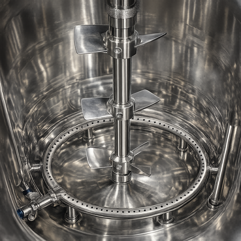
Mixing time and concentration gradients
Mixing time describes how quickly an introduced material becomes acceptably distributed within the vessel. It may be evaluated using conductivity, pH, temperature, tracer concentration, or another suitable measurement.
The study design should consider:
- Minimum and maximum working volume
- Representative fluid properties
- Agitation operating range
- Addition location
- Sensor location
- Direction of agitation
- Gas-flow conditions
- Required degree of uniformity
Poor mixing can create localized extremes following acid, base, nutrient, inducer, or antifoam addition. A bulk sensor may report an acceptable value while cells near the addition point experience a materially different condition.
Gas-delivery and exhaust architecture
Aerobic processes depend on controlled gas delivery and removal. The gas system may include:
- Air, oxygen, nitrogen, and carbon dioxide supplies
- Pressure regulators
- Mass-flow controllers
- Gas-mixing manifolds
- Ring or microspargers
- Overlay-gas connections
- Inlet sterile filters
- Vessel backpressure control
- Condensers
- Foam traps
- Exhaust filters
- Off-gas analyzers
- Exhaust treatment or containment devices
Gas identity, purity, supply capacity, pressure, and distribution should be appropriate for the intended process. Facility-level requirements are addressed in Process Gas Systems for GMP Manufacturing.
Oxygen transfer
Oxygen moves from the gas phase into the liquid phase and is then consumed by the biological culture. A common engineering relationship is: OTR=kLa(C∗−CL) , where:
- OTR is the oxygen-transfer rate
- kLa is the volumetric mass-transfer coefficient
- C∗ is the dissolved-oxygen concentration at saturation under the defined conditions
- CL is the actual dissolved-oxygen concentration in the liquid
The system must provide sufficient oxygen-transfer capability to meet the culture’s oxygen-uptake rate throughout the defined process. An acceptable dissolved-oxygen value at low biomass does not demonstrate adequate capacity at the maximum anticipated demand.
Oxygen-transfer capability depends on interacting factors:
- Agitation
- Gas-flow rate
- Oxygen concentration
- Sparger design
- Bubble size
- Backpressure
- Temperature
- Medium composition
- Antifoam concentration
- Cell or solids concentration
- Vessel scale
The maximum operating capacity is often reached when several cascade-controlled outputs approach their limits simultaneously.
Carbon dioxide removal
Carbon dioxide is generated by cellular metabolism and may also be deliberately added for pH control. Accumulation can affect intracellular conditions, pH, growth, productivity, and product quality. Carbon dioxide removal depends on:
- Gas-flow rate
- Agitation
- Headspace exchange
- Pressure
- Sparger configuration
- Medium properties
- Scale
- Exhaust resistance
Off-gas oxygen and carbon dioxide measurements can support process understanding and mass-balance calculations, but they must be interpreted with gas flow, pressure, humidity, and analyzer performance.
Pressure and exhaust control
Vessel pressure affects gas solubility, oxygen transfer, exhaust flow, sterile-boundary integrity, and mechanical safety. The system may use an automated backpressure valve or another controlled restriction in the exhaust path. The design should address:
- Normal operating-pressure range
- Maximum allowable working pressure
- Vacuum exposure
- Pressure-relief protection
- Exhaust-filter pressure drop
- Condensation in vent lines
- Blocked-filter response
- Valve failure positions
- Pressure behavior during additions and transfers
- Pressure behavior during CIP or SIP
- Single-use container pressure limitations
A wet, fouled, or obstructed exhaust filter can increase vessel pressure even when the pressure-control valve is fully open. Pressure protection must therefore account for credible exhaust restrictions rather than rely solely on normal control-loop operation.
Temperature-control system
Biological activity, mixing, gas compression, and equipment operation can add heat to the process. The temperature-control system must both heat the initial charge and remove heat generated during operation. Typical components include:
- Vessel jacket or internal heat-transfer surface
- Temperature-control unit
- Heating and cooling utilities
- Circulation pump
- Control valve
- Supply and return temperature measurement
- Product-temperature sensor
- Automated control loop
Functional design should consider:
- Minimum and maximum working volume
- Required heating and cooling rates
- Worst-case metabolic heat load
- Utility temperatures and seasonal capability
- Temperature uniformity
- Control-loop response
- Overshoot and oscillation
- Recovery following additions
- Failure of heating or cooling supply
The product-temperature sensor must represent the process adequately. Strong mixing supports representative measurement, but sensor position, immersion, response time, and local flow conditions remain important.
Addition, inoculation, sampling, and harvest systems
Materials may enter or leave the bioreactor through several controlled paths:
- Initial medium charge
- Inoculum transfer
- Nutrient feeds
- Acid and base addition
- Antifoam addition
- Inducer or supplement addition
- Sample withdrawal
- Perfusion or bleed
- Product harvest
- Waste removal
The design should provide:
- Correct routing
- Adequate flow range
- Low hold-up volume
- Drainability
- Backflow prevention
- Sterile or closed connections
- Protection against incorrect additions
- Controlled pump direction and speed
- Accurate material accounting
- Appropriate line-clearance and changeover controls
Load cells or balances may support addition control and mass reconciliation. Their usable range, resolution, environmental sensitivity, piping influence, and zeroing strategy must be considered.
Sampling systems should provide representative samples without creating unacceptable contamination or exposure risk. Sample-line volume, flushing requirements, temperature, frequency, and cumulative volume loss may affect process interpretation.
Instrumentation and measurement systems
Common measurements include:
- Temperature
- pH
- Dissolved oxygen
- Vessel pressure
- Agitation speed
- Gas flow
- Feed flow or delivered mass
- Vessel weight or level
- Foam
- Exhaust oxygen
- Exhaust carbon dioxide
- Conductivity, capacitance, optical density, or other process-specific measurements
Measurement suitability depends on the complete measurement chain:
- Sensor
- Mounting location
- Cable or transmitter
- Signal conversion
- Scaling
- Controller input
- Display
- Alarm
- Data record
- Calibration and maintenance controls
Sensor selection and lifecycle control are addressed in Bioreactor Instrumentation, Sensors, and Automation.
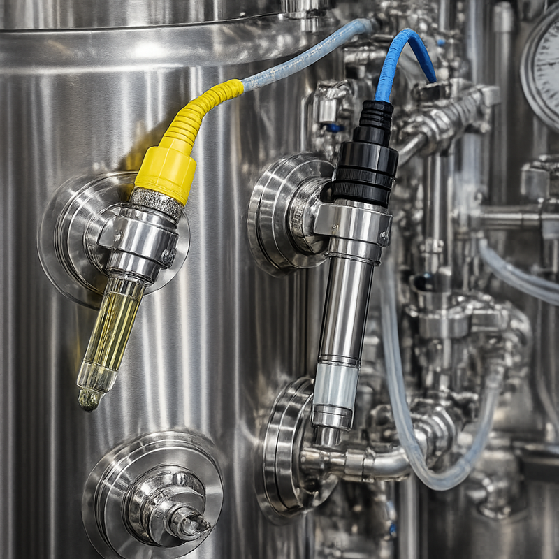
pH and dissolved-oxygen probes are commonly inserted directly into the controlled process volume. Their location, immersion, sanitary connection, calibration, response, and resistance to repeated processing cycles affect the reliability of the values used by the control system.
pH control
pH can affect growth, metabolism, nutrient availability, product formation, and impurity profiles. Control commonly uses one or more of the following:
- Acid addition
- Base addition
- Carbon dioxide addition
- Bicarbonate or buffer control
- Feed composition
- Gas-stripping strategy
The control strategy should address:
- Measurement accuracy and response
- Pre-use and post-use calibration checks
- Probe drift during long runs
- Dosing-pump range and resolution
- Addition-point location
- Mixing delay
- Control deadband
- Maximum dosing rate
- Overshoot protection
- Total addition limits
- Response to probe failure
A poorly configured loop may alternate between acid and base additions or create localized pH extremes. Stable display values alone do not demonstrate an appropriate control strategy.
Dissolved-oxygen control
Dissolved oxygen is frequently controlled through a cascade that progressively manipulates available outputs. A possible sequence is:
- Increase agitation speed.
- Increase airflow.
- Enrich inlet gas with oxygen.
- Increase vessel backpressure.
The actual sequence should reflect the equipment, process, shear sensitivity, foaming tendency, gas-transfer capability, and safety strategy.
Cascade control should define:
- Output order
- Transition points
- Minimum and maximum outputs
- Rate-of-change limits
- Override conditions
- Anti-windup behavior
- Response if an output becomes unavailable
- Alarm conditions
- Manual-control restrictions
A dissolved-oxygen setpoint can remain unmet even when the control loop is functioning correctly if the culture’s oxygen demand exceeds the physical capability of the system. This is an equipment-capacity or process-design limitation, not necessarily an instrument failure.
Foam control
Foam can reduce usable headspace, wet or obstruct the exhaust filter exhaust filter, interfere with gas transfer, affect level or capacitance measurements, and create contamination or containment concerns. Controls can include:
- Adequate headspace
- Mechanical foam breakers
- Foam probes
- Automated antifoam addition
- Gas-flow adjustment
- Agitation adjustment
- Exhaust-line foam traps
Antifoam can affect oxygen transfer, downstream filtration, purification, and product recovery. Automated addition should therefore be limited and recorded. Foam-probe failure, coating, false activation, and loss of antifoam supply should be addressed in the failure strategy.
Automation and process-control architecture
The control system integrates instruments, actuators, recipes, sequences, alarms, calculations, displays, and electronic records. Typical architecture includes:
- Programmable logic controller or distributed control system
- Human-machine interface
- Local instrument controllers
- Variable-frequency drives
- Input/output modules
- Recipe-management functions
- Alarm management
- Batch reporting
- Historian or data archive
- Interfaces with manufacturing or laboratory systems
Automation should maintain the process within defined conditions while making abnormal operation visible. It should not conceal loss of physical capability behind automatic output changes.
The automation platform receives process measurements, executes control logic, manipulates equipment outputs, manages recipes and alarms, and records process data. The control cabinet and operator interface shown below represent the connection between field instrumentation and automated bioreactor operation.
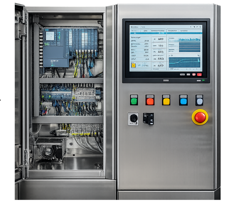
Control recipes and phases
A bioreactor recipe may control:
- Preparation
- Cleaning
- Sterilization
- Pressure or leak testing
- Media charge
- Temperature conditioning
- Probe preparation
- Inoculation
- Batch cultivation
- Feed phases
- Induction
- Perfusion
- Harvest
- Shutdown
For each phase, the recipe should define:
- Entry conditions
- Setpoints
- Permitted ranges
- Active control loops
- Required equipment states
- Operator actions
- Transition criteria
- Hold conditions
- Alarm behavior
- Abort or recovery logic
Recipe control must distinguish authorized process parameters from operator-adjustable settings. Changes affecting approved recipes, calculation logic, alarm limits, or critical sequences require controlled assessment.
Alarm and interlock strategy
Relevant conditions may include:
- High or low temperature
- High or low pH
- Low dissolved oxygen
- High pressure
- Agitator failure
- Gas-supply failure
- Exhaust restriction
- Feed interruption
- Excessive feed delivery
- Foam detection
- Loss of cooling
- Loss of power
- Communication failure
- Sensor failure or disagreement
- Single-use bag leak
- Valve-position failure
Alarm limits should be based on process and equipment knowledge. They should not simply duplicate control setpoints. Interlocks and automated protective actions must be selected according to the consequence of continued operation, abrupt shutdown, or uncontrolled transition.
Electronic records and GMP-relevant computerized functions must be controlled consistently with 21 CFR 211.68. Detailed lifecycle planning is addressed in Computerized Systems Validation Planning.
CIP, SIP, and sterile-boundary interfaces
Reusable bioreactors may be integrated with automated cleaning and sterilization systems. The design must support effective delivery, return, venting, drainage, sequencing, and monitoring.
CIP interface
The equipment design should address:
- Spray-device selection and location
- Internal component coverage
- Flow and pressure requirements
- Cleaning-solution concentration
- Heating capability
- Return conditions
- Drainability
- Cleaning of addition, sample, harvest, and instrument paths
- Valve and gasket exposure
- Prevention of cleaning-solution retention
Qualification of the integrated Clean-in-Place system demonstrates equipment and cycle functionality. Product-residue removal remains subject to the separate Cleaning Validation Approach.
SIP interface
SIP effectiveness depends on the complete sterilized boundary, not only the vessel temperature. The design should support:
- Air removal
- Steam access
- Condensate removal
- Appropriate venting
- Temperature measurement at justified locations
- Sterilization of filters and connected paths
- Valve sequencing
- Pressure control
- Post-SIP integrity
- Controlled transition to the process state
Detailed integrated-cycle requirements are addressed in Steam-in-Place Utility Systems.
Sterility is a system property. A satisfactory vessel-temperature reading does not compensate for an unsterilized branch, trapped air, retained condensate, incorrectly positioned valve, damaged gasket, or compromised sterile filter.
Scale-up and scale-down
Performance does not scale through vessel volume alone. Changes in geometry and scale can alter:
- Mixing time
- Power input per unit volume
- Impeller tip speed
- Oxygen-transfer capability
- Gas-flow regime
- Carbon dioxide removal
- Hydrostatic pressure
- Heat-transfer area relative to volume
- Addition and sampling behavior
- Sensor response
- Foam formation
- Shear exposure
Scale-up may use one or more engineering criteria, but no single criterion can normally remain constant simultaneously across every scale. The selected approach must reflect the biological process and the most important sources of risk.
Scale-down models should reproduce the conditions relevant to their intended use. A development-scale bioreactor does not become representative merely because it uses the same nominal setpoints as the production system.
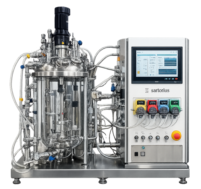
Bench-scale systems are used for process development, characterization, troubleshooting, and scale-transition studies. Their usefulness depends on how well they reproduce the production-scale conditions relevant to the study rather than on superficial similarity or matching nominal setpoints.
Process transfers and system integration
The bioreactor rarely operates independently. Interfaces may include:
- Media and buffer preparation systems
- Seed reactors
- Feed vessels
- Gas utilities
- CIP and SIP systems
- Cell-retention devices
- Harvest vessels
- Centrifugation or clarification equipment
- Filtration systems
- Waste-inactivation systems
- Building automation
- Manufacturing execution systems
- Data historians
Integration risks include:
- Incorrect routing
- Incompatible pressures
- Backflow
- Loss of sterile boundary
- Incomplete line clearance
- Communication failure
- Timing discrepancies
- Uncontrolled holds
- Incorrect equipment-state assumptions
- Incomplete transfer
- Unreconciled material losses
The boundary and responsibility of each connected system should be defined before design review and qualification.
Equipment capability and process validation boundary
Bioreactor design and qualification establish that the equipment can perform its intended functions within approved ranges. Examples include demonstrating:
- Agitation over the required operating range
- Acceptable mixing performance
- Gas-flow and pressure-control capability
- Temperature-control performance
- Pump and addition-system accuracy
- Correct valve sequencing
- Alarm and interlock response
- Recipe execution
- Sterile-boundary functions
- Data acquisition and reporting
These studies do not independently establish that a specific biological process consistently produces acceptable product.
Product-specific process validation must integrate:
- Cell bank and inoculum controls
- Raw-material attributes
- Process parameters
- Biological variability
- Culture duration
- Product and impurity responses
- Scale and batch-size effects
- Sampling and analytical controls
- Process Performance Qualification
- Continued Process Verification
FDA’s process-validation guidance explicitly separates qualification of facilities, utilities, and equipment from Process Performance Qualification within Stage 2 of the lifecycle. FDA Process Validation: General Principles and Practices.
Functional failure conditions
Design and control strategies should address credible failure conditions rather than only normal operation.
| Failure condition | Potential effect | Expected control |
|---|---|---|
| Agitator trip or speed loss | Poor mixing, oxygen depletion, settling or gradients | Alarm, defined response, restart assessment and batch-impact evaluation |
| Gas-supply interruption | DO loss, altered pH or loss of overlay protection | Supply monitoring, alarms, reserve capacity or defined recovery strategy |
| Exhaust-filter blockage | Increasing pressure and loss of gas flow | Pressure monitoring, relief protection and controlled response |
| Temperature-control failure | Temperature drift or loss of process viability | Alarms, utility-failure response and recovery limits |
| pH-probe drift | Incorrect reagent addition or misleading process record | Calibration controls, plausibility checks and post-use assessment |
| DO-probe failure | Incorrect cascade response | Sensor diagnostics, manual strategy or defined alternate control |
| Feed-pump malfunction | Incorrect nutrient delivery and altered process trajectory | Mass reconciliation, flow or weight verification and alarms |
| Foam-probe failure | Uncontrolled foam or unnecessary antifoam addition | Visual or secondary indication and dosing limits |
| Valve-position failure | Incorrect routing, isolation failure or contamination risk | Position feedback, permissives and sequence interlocks |
| Loss of power or automation | Uncontrolled equipment state and incomplete records | Defined safe state, backup strategy and controlled recovery |
| Single-use assembly leak | Loss of containment, sterility or batch material | Installation checks, pressure limits, monitoring and response procedure |
Recovery must be based on scientific and procedural justification. Returning a parameter to its setpoint does not automatically eliminate the effect of the excursion.
Lifecycle control
Bioreactor functionality must remain controlled after initial release. Relevant lifecycle evidence includes:
- Calibration results and instrument drift
- Preventive and corrective maintenance
- Seal, bearing, impeller, valve, and gasket condition
- Alarm and deviation history
- Control-loop performance
- Batch parameter trends
- Cleaning and sterilization performance
- Filter failures
- Software and recipe changes
- Replacement of sensors or single-use components
- Utility changes
- Process changes
- Equipment modifications
- Supplier changes
- Obsolescence and spare-parts status
Measurement systems should be controlled through the GMP Calibration Program and Metrology Control. Mechanical and reliability risks should be addressed through Preventive Maintenance and System Reliability Strategy.
Changes should be assessed according to the functions, requirements, process parameters, records, and qualified conditions they can affect. The possible response may range from documented verification to targeted or broader requalification. General principles are addressed in GMP Change Control and Validation Impact Assessment and Risk-Based Requalification of GMP Equipment.
Documentation
The controlled equipment record should identify or reference:
- Intended use
- System description and boundaries
- Process and instrumentation diagrams
- Equipment and component specifications
- Material and surface-finish records
- Operating ranges and design limits
- Instrument list
- Alarm and interlock schedule
- Control narrative
- Recipe and configuration baseline
- Utility requirements
- Cleaning and sterilization strategy
- Single-use assembly specifications, where applicable
- Qualification records
- Calibration and maintenance requirements
- Operating and recovery procedures
- Change history
- Periodic-review and requalification decisions
Documentation should connect the biological process requirements to the physical equipment functions that support them. Unsupported statements that a system is “suitable,” “validated,” or “GMP compliant” are insufficient without defined requirements and objective evidence.
Conclusion
Bioreactor functionality results from the coordinated performance of the vessel, agitation system, gas path, temperature-control system, additions, sampling and harvest paths, sensors, automation, utilities, and sterile or containment boundary.
The design must provide sufficient operating capability for the intended biological process while controlling mixing, mass transfer, heat removal, pressure, additions, contamination risks, and process data. Equipment qualification then verifies that these functions operate as intended. Product-specific process validation separately establishes that the integrated manufacturing process can reproducibly produce acceptable product.