

Bioreactor Instrumentation, Sensors, and Automation
Purpose and scope
Bioreactor instrumentation provides the measurements required to observe biological conditions, execute automated control, detect abnormal operation, and document process performance. Reliable control depends on the complete measurement chain—from the process sensor through signal transmission, controller configuration, operator display, alarm handling, and electronic record.
This article addresses instrumentation and automation used with stainless-steel and single-use bioreactors and fermenters. It covers sensor selection, installation, measurement performance, calibration, control loops, recipes, alarms, data handling, failure detection, maintenance, and lifecycle control.
The mechanical and process architecture is addressed in Bioreactor and Fermenter Design, Functionality, and Process Control. Detailed verification is addressed in Bioreactor Qualification and Lifecycle Control. Full computerized-system validation and Part 11 assessment remain separate but connected activities.
Lifecycle position and system boundary
Instrumentation and automation requirements should be established during bioreactor design rather than added after mechanical selection. The intended process determines:
- Parameters that must be measured
- Required measurement ranges
- Accuracy and resolution
- Response-time requirements
- Control-loop functions
- Alarm and interlock requirements
- Data-recording frequency
- Recipe and phase logic
- Calibration strategy
- Redundancy or alternate measurements
- Failure-response requirements
- Electronic-record and data-retention needs
The system boundary may include:
- Process sensors and probes
- Sensor housings and process connections
- Transmitters and signal converters
- Mass-flow controllers
- Pumps and variable-frequency drives
- Valve actuators and position feedback
- Programmable logic controller or distributed control system
- Human-machine interface
- Recipe-management functions
- Alarm and event handling
- Local and remote data storage
- Historian or batch-reporting interface
- Network, time-service and external-system interfaces
A boundary drawing should distinguish bioreactor equipment functions from shared automation infrastructure, facility utilities, manufacturing systems and separately managed computerized systems.
Measurement and control architecture
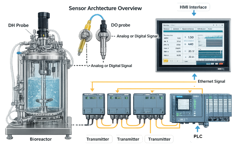
A bioreactor measurement does not originate at the HMI. It passes through a chain of physical and electronic elements:
- The process condition acts on the sensing element.
- The sensor produces a physical or electrical response.
- A transmitter or signal conditioner converts that response.
- The signal is transferred to a controller input.
- Scaling and engineering units are applied.
- Control logic compares the value with the applicable setpoint.
- The controller manipulates an output.
- The value, output and system state are displayed and recorded.
Each element can introduce error, delay, noise, loss of resolution or incorrect configuration.
The illustration below presents this relationship from the process sensor through the control and operator interfaces.
Instrument criticality and measurement requirements
Not every bioreactor measurement has the same GMP significance. Criticality depends on intended use rather than instrument type.
A temperature sensor used for product control can have a different impact from a temperature indicator used only for maintenance troubleshooting. A pressure transmitter used to protect the vessel may perform a safety function, while another pressure signal may support a GMP process record.
Criticality assessment should consider:
- Relationship to a critical process parameter
- Potential influence on product quality
- Use in automated control
- Use for batch acceptance or release
- Role in contamination or sterile-boundary control
- Role in an alarm, interlock or protective function
- Availability of an independent measurement
- Detectability of failure
- Consequence of incorrect, delayed or missing data
Measurement requirements should define more than the nominal operating setpoint.
| Requirement | Design consideration |
|---|---|
| Range | Must include normal, challenge, cleaning, sterilization and credible excursion conditions |
| Accuracy | Must be suitable relative to the process tolerance |
| Resolution | Must allow meaningful display, control and recording |
| Repeatability | Must support consistent measurement under equivalent conditions |
| Response time | Must be fast enough for the process dynamics and control objective |
| Drift | Must remain acceptable throughout the intended operating period |
| Environmental resistance | Must address temperature, pressure, moisture, vibration and cleaning exposure |
| Calibration | Must be achievable using appropriate standards and procedures |
| Data use | Must identify whether the value controls, alarms, calculates or records GMP information |
Using an instrument with a range far beyond the actual process can reduce useful resolution or measurement capability. Selection should reflect the complete operating and maintenance envelope without unnecessarily sacrificing performance in the normal process range.
pH measurement
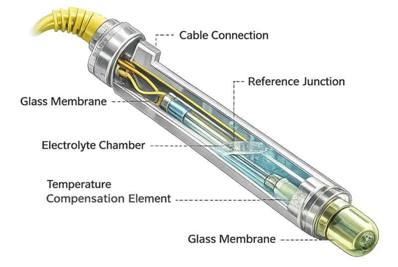
Glass-electrode pH probes are widely used in reusable bioreactors. A typical assembly includes:
- pH-sensitive glass membrane
- Internal reference system
- Reference junction
- Electrolyte
- Temperature-compensation element
- Sensor body and sanitary process connection
- Cable or digital transmitter
Probe performance can be affected by:
- Coating or fouling
- Reference-junction degradation
- Electrolyte depletion
- Cracked glass
- Electrical noise
- Temperature-compensation errors
- Repeated SIP exposure
- Long operating duration
- Improper storage
- Process-medium composition
The illustration below shows the principal internal features responsible for pH measurement and the locations susceptible to degradation.
Calibration and in-process verification
A common strategy includes:
- Two-point calibration before use
- Use of appropriate, traceable buffer standards
- Verification that the calibration slope and offset are acceptable
- Confirmation of temperature compensation
- Post-process or post-use verification
- Assessment of drift between pre-use and post-use checks
The specific strategy depends on process duration, probe technology, system design and whether the probe can be removed or checked during operation.
A post-use discrepancy does not automatically establish when the measurement became inaccurate. The assessment should consider the error magnitude, direction, process trends, redundant indications, laboratory results, control activity and last documented acceptable condition.
Dissolved-oxygen measurement
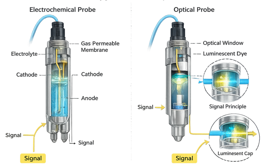
Dissolved oxygen may be measured using electrochemical or optical technology.
Electrochemical sensors
Electrochemical probes consume a small amount of oxygen as part of the measurement mechanism. Performance depends on:
- Membrane condition
- Electrolyte condition
- Polarization
- Flow past the sensing surface
- Temperature compensation
- Cathode and anode condition
- Calibration stability
Maintenance can include membrane and electrolyte replacement.
Optical sensors
Optical sensors use an oxygen-sensitive luminescent material. Oxygen affects the measured light response, allowing dissolved-oxygen concentration to be calculated.
Potential advantages include reduced oxygen consumption and lower routine maintenance. However, optical components can age, drift or be affected by repeated sterilization and process exposure.
The following illustration compares the two measurement principles.
Calibration conditions
Dissolved-oxygen calibration should define:
- Zero reference
- Span reference
- Temperature
- Pressure
- Gas composition
- Agitation and flow conditions
- Stabilization time
- Acceptance criteria
A nominal “100%” calibration depends on the defined gas, pressure, temperature and liquid conditions. Changes in atmospheric pressure, vessel pressure or gas composition can affect the relationship between oxygen concentration and percent saturation.
Temperature measurement
Resistance temperature detectors are commonly used because they provide appropriate accuracy and stability across typical bioreactor operating ranges. Thermocouples may be used where their characteristics better suit the application.
Design considerations include:
- Measurement range
- Required accuracy
- Sensor class
- Number of sensing elements
- Immersion depth
- Thermowell design
- Response time
- Installation location
- SIP temperature exposure
- Transmitter and controller scaling
Large bioreactors may contain multiple temperature sensors for control, indication, verification or sterilization monitoring. Their functions should be distinguished. Agreement criteria should reflect expected sensor accuracy, location and process uniformity.
The process-control sensor should not be assumed to demonstrate complete vessel temperature distribution during qualification or SIP validation.
Pressure measurement
Pressure measurements may support:
- Vessel-pressure control
- Exhaust backpressure control
- Filter-differential pressure
- Single-use assembly protection
- SIP pressure monitoring
- Leak or pressure-hold testing
- Alarm and relief-system coordination
Pressure transmitters must be compatible with the applicable process fluids, cleaning agents and SIP conditions. Installation should avoid condensate pockets, gas traps, blocked impulse paths and orientations that impair drainage.
The control range should provide useful measurement resolution while accommodating credible operating and excursion conditions.
Gas-flow measurement and control
Mass-flow controllers can regulate air, oxygen, nitrogen and carbon dioxide supplied to the vessel. Their performance affects:
- Dissolved-oxygen control
- pH control
- Gas-transfer capability
- Carbon dioxide removal
- Overlay conditions
- Foam behavior
- Process calculations
Requirements should address:
- Gas identity
- Minimum and maximum flow
- Accuracy and repeatability
- Turndown
- Inlet-pressure requirements
- Gas correction factors
- Leak-tightness
- Response time
- Communication protocol
- Failure position
- Calibration for the intended gas
Substitution of one gas, controller or calibration basis for another requires technical evaluation. A controller calibrated for one gas may not report the correct mass flow for a different gas without appropriate configuration or correction.
Facility supply and distribution requirements are addressed in Process Gas Systems for GMP Manufacturing.
Weight, level and feed measurement
Bioreactor systems may use load cells, platform scales, balance feedback, pressure-derived level or other methods to determine vessel contents and material additions. Load-cell performance can be affected by:
- Rigid piping connections
- Hose tension
- Vessel supports
- Thermal expansion
- Agitator vibration
- Uneven load distribution
- Zeroing practices
- Environmental disturbance
- Addition-system contact with the vessel
Feed delivery may be verified by:
- Pump calibration
- Source-container weight loss
- Receiving-vessel weight gain
- Flow measurement
- Time and pump-speed calculation
- Material reconciliation
The selected method should be capable of detecting delivery errors relevant to the process. Pump speed or running time alone may not demonstrate actual delivery when tubing wear, occlusion, loss of prime or blockage is possible.
Foam and process-state detection
Foam probes commonly detect contact between foam and a conductive or capacitive sensing element. Their performance can be affected by:
- Probe coating
- Liquid splashing
- Condensate
- Installation height
- Sensitivity settings
- Process conductivity
- Electrical grounding
Automated antifoam addition should include appropriate limits because excessive antifoam can affect oxygen transfer and downstream processing.
Other process-state measurements may include:
- Capacitance-based viable biomass
- Optical density
- Raman or near-infrared measurements
- Conductivity
- Redox potential
- Glucose, lactate or metabolite analyzers
- Off-gas oxygen and carbon dioxide
These technologies require an intended-use-specific assessment of measurement reliability, calibration or model maintenance, sampling representativeness, interfaces and data use.
Single-use sensors
Single-use bioreactors can use disposable:
- Optical pH and dissolved-oxygen sensor patches
- Pressure sensors
- Temperature elements
- Conductivity sensors
- Flow sensors
- Foam or level detectors
The complete measurement function may include a disposable sensing element and reusable reader or transmitter. Controls should address:
- Correct sensor type and range
- Supplier and lot traceability
- Irradiation effects
- Shelf life and storage
- Reader compatibility
- Installation and alignment
- Calibration or factory calibration
- Single-point adjustment, where applicable
- Connection to the control system
- Replacement or failure response
Factory calibration does not eliminate the need to establish suitability for the intended measurement and process conditions.
Sensor installation and sanitary integration
Calibration cannot compensate for an inappropriate installation. Probe location and orientation affect whether the sensor measures representative process conditions. Installation design should consider:
- Required immersion depth
- Working-volume range
- Impeller and sparger location
- Vessel circulation pattern
- Gas entrainment
- Surface turbulence
- Addition points
- Potential stagnant regions
- Mechanical vibration
- Accessibility
- Drainability
- Hygienic connection design
- SIP steam access and condensate removal
The illustration below compares representative placement within the mixed process volume with locations susceptible to gas pockets or stagnant conditions.
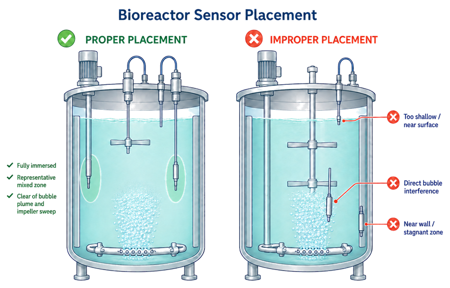
Sensor location should be justified by vessel geometry and process behavior rather than mechanical convenience. A stable signal can still be incorrect if it represents a localized condition rather than the bulk process.
Signal transmission and configuration
Sensor signals may be analog, digital or network-based. The measurement chain can include:
- Sensor
- Preamplifier
- Transmitter
- Analog-to-digital conversion
- Input module
- Controller scaling
- Signal filtering
- Display formatting
- Historian processing
Configuration elements requiring control include:
- Input type
- Engineering units
- Lower and upper range
- Linearization
- Damping or filtering
- Temperature compensation
- Gas correction factor
- Calibration coefficients
- Decimal precision
- Alarm limits
- Bad-signal behavior
Incorrect scaling can produce a believable but inaccurate displayed value. Verification must therefore challenge the complete measurement chain, not only the sensor or local transmitter.
Electrical design should address shielding, grounding, isolation, cable routing, moisture protection and electromagnetic interference. Noise filtering should not be so aggressive that it conceals a meaningful process change or creates unacceptable response delay.
Calibration and metrology control
Calibration establishes the relationship between the instrument indication and an appropriate reference over the required measurement range. The strategy should be based on intended use, criticality, drift history, process tolerance and manufacturer information.
The following illustration presents the controlled lifecycle from scheduled calibration through assessment and return to service.
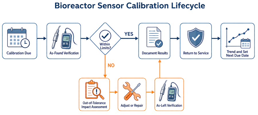
Calibration procedure
The calibration procedure should define:
- Instrument identification
- Calibration range and points
- Reference standards
- Environmental or process conditions
- Stabilization requirements
- Permitted adjustments
- Acceptance limits
- As-found and as-left recording
- Calculation and rounding conventions
- Failure and escalation requirements
- Labeling and return-to-service controls
Acceptance limits should be appropriate relative to the process requirement. A calibration tolerance equal to the complete allowable process variation may leave no allowance for other sources of measurement uncertainty or process variation.
As-found and as-left results
The as-found result shows instrument condition before adjustment. It is essential for determining whether previously generated data may have been affected.
The as-left result demonstrates instrument condition after adjustment or calibration work. Recording only the as-left result removes evidence needed to evaluate historical performance.
An out-of-tolerance condition requires assessment of:
- Error magnitude and direction
- Potentially affected period
- GMP uses of the measurement
- Process values recorded during that period
- Control actions driven by the signal
- Available independent or redundant evidence
- Potential product or batch impact
- Corrective action and recurrence risk
Program-level requirements are addressed in GMP Calibration Program and Metrology Control.
Sterilization, cleaning and sensor survivability
Reusable probes can be exposed to:
- Steam-in-place cycles
- Clean-in-place chemicals
- Elevated temperature
- Pressure cycling
- Rapid temperature changes
- Process media
- Storage solutions
- Repeated insertion and removal
These exposures can cause:
- pH reference-junction deterioration
- Glass-membrane aging
- DO membrane damage
- Optical-patch degradation
- Seal or O-ring deterioration
- Cable damage
- Moisture intrusion
- Changed response time
- Increased drift
The sensor specification and maintenance strategy should reflect actual exposure. A probe described as sterilizable may still have a finite validated or manufacturer-supported life.
CIP and SIP interfaces should be evaluated with the applicable Clean-in-Place system qualification and Steam-in-Place Utility Systems rather than treated only as sensor environmental conditions.
Response time and measurement dynamics
A sensor can remain accurate at equilibrium while responding too slowly for effective process control.
Dynamic performance depends on:
- Sensor technology
- Protective membrane or coating
- Thermowell construction
- Process flow at the sensing surface
- Signal filtering
- transmitter damping
- controller scan time
- network update frequency
- historian collection interval
Response requirements should be related to the process. A rapid addition or gas-control loop may require faster measurement than a slowly changing parameter used only for trending.
Changes in response time can be an early indication of fouling, membrane aging, poor flow or signal-processing changes.
Drift trending and predictive control
Calibration history can reveal progressive degradation before a complete failure occurs. Trending may use:
- Calibration offset
- Calibration slope
- Zero and span error
- Response time
- Number of SIP cycles
- Operating hours
- Probe age
- Failure and replacement history
The illustration below shows gradual drift approaching an established limit.
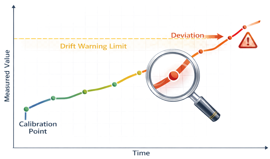
A warning threshold may support investigation or planned replacement before an out-of-tolerance condition occurs. It should not be confused with the approved calibration acceptance limit.
Calibration intervals may be shortened or extended when supported by adequate history, risk assessment and controlled change. Interval changes should not be based only on scheduling convenience.
Control loops and cascade control
A control loop connects:
- Measured process variable
- Setpoint
- Control algorithm
- Manipulated output
- Physical process response
Proportional-integral-derivative control is commonly used, but appropriate tuning depends on process dynamics. Poor tuning can produce:
- Sustained oscillation
- Overshoot
- Slow recovery
- Excessive actuator movement
- Alternating acid and base addition
- Abrupt cascade transitions
- Apparent control that masks equipment-capacity limitations
Loop performance should be evaluated across the approved operating range and relevant process phases.
Dissolved-oxygen cascade
A dissolved-oxygen cascade may manipulate:
- Agitation
- Airflow
- Oxygen enrichment
- Backpressure
The sequence should define:
- Order of outputs
- Transition points
- Output limits
- Ramp rates
- Interaction with foam control
- Shear restrictions
- Failure behavior
- Manual-mode restrictions
If all outputs reach their limits while dissolved oxygen remains below setpoint, the automation may be operating correctly while the physical system lacks sufficient oxygen-transfer capability.
pH control
pH control may manipulate:
- Acid addition
- Base addition
- Carbon dioxide
- Gas stripping
- Feed composition
The control strategy should account for mixing delay and local concentration effects. Dosing limits, deadbands and totalized additions can help prevent uncontrolled correction following a faulty or slowly responding measurement.
Temperature control
Temperature control may manipulate heating and cooling valves, temperature-control-unit setpoints or circulation functions. Tuning must reflect process volume, jacket response, metabolic heat generation and utility capacity.
Recipes, phases and parameter management
Automation may organize operation into controlled phases such as:
- Preparation
- Leak testing
- CIP
- SIP
- Media charge
- Temperature conditioning
- Inoculation
- Cultivation
- Feeding
- Induction
- Perfusion
- Harvest
- Shutdown
Each phase should define:
- Entry conditions
- Required equipment state
- Setpoints and limits
- Active control loops
- Permitted operator actions
- Transition criteria
- Hold conditions
- Alarm behavior
- Abort and recovery logic
Critical parameters should be protected from unauthorized or undocumented modification. The system should distinguish approved recipe values, temporary operator adjustments, engineering configuration and maintenance settings.
Alarms, interlocks and failure response
Alarms notify personnel that defined conditions require attention. Interlocks prevent or terminate an action when required conditions are not satisfied. They are related but not interchangeable.
The strategy should address:
- Alarm priority
- Setpoint and delay
- Deadband
- Latching
- Acknowledgement
- Suppression or shelving
- Required response
- Escalation
- Event recording
- Return-to-normal behavior
Relevant failure conditions include:
| Failure | Detection or secondary evidence | Possible automated response |
|---|---|---|
| Sensor signal loss | Bad-quality flag, open circuit or communication alarm | Hold output, transfer control or enter defined safe mode |
| Frozen signal | No response despite known process change | Alarm or sensor-disagreement detection |
| Gradual drift | Calibration trend, redundant sensor or material balance | Investigation, recalibration or replacement |
| Excessive noise | Rate-of-change or variability monitoring | Alarm, alternate measurement or controlled filtering |
| Mass-flow-controller failure | Command-versus-feedback disagreement | Isolate affected gas or transfer control |
| Feed-pump failure | Weight, flow or delivered-mass discrepancy | Stop phase, alarm or controlled recovery |
| Valve-position failure | Command-versus-position disagreement | Prevent sequence transition |
| PLC or communication failure | Watchdog or communication alarm | Defined fail-safe equipment state |
| Historian failure | Interface or data-collection alarm | Local buffering or controlled operating restriction |
| Loss of power | System-status and equipment-state detection | UPS-supported control, controlled shutdown or recovery procedure |
Fail-safe behavior must consider the biological process. Abruptly closing every valve or stopping every output may protect equipment but destroy the batch or create another hazard. Safe-state design must evaluate equipment, personnel, containment and product consequences.
Manual mode and overrides
Manual control may be necessary for setup, maintenance, troubleshooting or controlled recovery. It can also bypass normal automation protections.
Controls should define:
- Authorized users
- Permitted manual functions
- Status indication
- Alarm behavior
- Interlock behavior
- Time limits
- Reason documentation
- Event or audit-trail recording
- Review and return to automatic operation
A manual override should not silently disable a GMP control or remove evidence of the intervention.
Electronic records and data integrity
Bioreactor automation can create or maintain records used for:
- Batch execution
- Process trending
- Deviation assessment
- Process validation
- Batch review or release
- Calibration
- Maintenance
- Recipe management
- Alarm and event history
Relevant controls may include:
- Unique user identification
- Role-based access
- Audit trails
- Accurate timestamps
- Time synchronization
- Record protection
- Backup and recovery
- Data retention
- Review of changes
- Controlled report generation
- Secure interfaces
The applicability of 21 CFR Part 11 depends on whether electronic records or signatures are used to meet FDA record requirements. Detailed assessment is addressed in 21 CFR Part 11 Compliance and Checklist.
Data should remain attributable, legible, contemporaneous, original, accurate, complete, consistent, enduring and available. Application of these principles is addressed in ALCOA+ Principles and Implementation.
Under 21 CFR 211.68, automatic, mechanical and electronic equipment used in drug manufacturing must be routinely calibrated, inspected or checked under a written program designed to assure proper performance.
Interfaces and time synchronization
Bioreactor controls may interface with:
- Data historians
- Manufacturing execution systems
- Electronic batch records
- Laboratory systems
- Building-management systems
- Utility monitoring systems
- Recipe servers
- Network time services
- Remote alarm-notification platforms
Interface requirements should define:
- Source and destination
- Data elements
- Units and precision
- Transfer frequency
- Data ownership
- Error detection
- Retry or buffering
- Duplicate prevention
- Time basis
- Reconciliation
- Recovery following interruption
The sending system, receiving system and interface can each function individually while transferred data remain incomplete or incorrect. Interface verification must therefore confirm end-to-end transfer and error handling.
Instrument and automation qualification boundary
Equipment qualification should verify GMP-relevant instrumentation and automation functions such as:
- Installed sensor and transmitter identity
- Range and scaling
- Calibration status
- Control-loop behavior
- Recipe and phase execution
- Alarm and interlock operation
- Valve sequencing
- Failure and recovery response
- Data display and recording
- Applicable interfaces
- Configuration baseline
A broader computerized-system lifecycle may also address:
- Supplier assessment
- Software and configuration specifications
- Requirements traceability
- User and access management
- Audit trails
- Electronic signatures
- Backup and recovery
- Cybersecurity
- Infrastructure
- Periodic access and audit-trail review
- Software change control
The two scopes must be coordinated. Mechanical qualification should not claim that the entire computerized system has been validated merely because several HMI screens and control loops were tested. The validation strategy is addressed in Computerized Systems Validation Planning.
Maintenance and lifecycle control
Lifecycle control should include:
- Scheduled calibration
- Preventive maintenance
- Probe inspection and replacement
- Review of calibration drift
- Review of recurring alarms
- Control-loop performance review
- Backup and recovery verification
- Configuration management
- Spare-part and obsolescence control
- Supplier notices
- Change control
- Periodic assessment
- Risk-based requalification
Relevant changes include:
- Sensor make, model or technology
- Sensor location or insertion depth
- Range or scaling
- Calibration procedure or interval
- Alarm or interlock setting
- Control-loop tuning
- Cascade order
- Recipe parameter
- PLC logic
- HMI configuration
- Firmware
- Interface
- Historian or reporting function
- Network or infrastructure component
Replacement described as “like-for-like” still requires confirmation that specifications, firmware, configuration, materials, performance and installation remain equivalent.
General reliability controls are addressed in Preventive Maintenance and Equipment Reliability. Instrument and maintenance modifications should follow Change Impact on Calibration and Maintenance.
Periodic review
Periodic review should integrate:
- Calibration completion and out-of-tolerance history
- Drift and adjustment trends
- Sensor failures and replacement frequency
- Control-loop performance
- Recurring or nuisance alarms
- Overrides and manual operation
- Automation deviations
- Recipe and configuration changes
- Access and audit-trail concerns
- Data losses or interface failures
- Backup and recovery results
- Maintenance effectiveness
- Obsolescence and supplier support
- Open corrective actions
- Requalification status
The conclusion should determine whether the existing calibration, maintenance, monitoring and qualification controls remain adequate or require revision.
Documentation
Controlled documentation should include, as applicable:
- Instrument index
- Instrument specifications
- Criticality assessment
- Process and instrumentation diagrams
- Sensor-location drawings
- Input/output list
- Range and scaling records
- Alarm and interlock schedule
- Control narrative
- Recipe and phase specifications
- Calibration procedures and records
- Configuration baseline
- Software and firmware versions
- Interface specifications
- User and role definitions
- Backup and recovery procedures
- Maintenance instructions
- Qualification records
- Change history
- Periodic-review conclusions
Documentation must connect each important process measurement and automated function with its requirement, design configuration, verification method and lifecycle control.
Conclusion
Bioreactor control depends on more than selecting accurate probes. Measurement reliability results from correct sensor technology, representative installation, controlled signal processing, appropriate calibration, adequate response, sound control-loop design, effective alarms, trustworthy electronic records and disciplined lifecycle management.
Instrumentation and automation must be designed as part of the biological processing system. The objective is to ensure that process conditions are measured correctly, manipulated predictably, recorded reliably and maintained within the approved operating strategy throughout the equipment lifecycle.