

Filtration System Design and Critical Components
Introduction
Reliable filtration depends on more than selecting a membrane with the correct nominal pore size or molecular-weight cutoff. Performance is also affected by the filter format, available membrane area, housing or holder design, pump behavior, tubing and piping configuration, valve arrangement, instrumentation, pressure protection, material compatibility, venting, drainability, and control-system functions.
These components must work together without creating bypass paths, uncontrolled pressure, excessive shear, unacceptable hold-up, poor flow distribution, contamination risks, or conditions that damage the membrane or product.
This article examines the design and functional requirements of the critical components used in pharmaceutical and biopharmaceutical filtration systems. Overall system configuration and process-stream relationships are addressed in filtration and ultrafiltration system architecture.
Establishing the Component Design Basis
Component selection should begin with the intended use of the filtration step. The design basis should identify:
- Process purpose, such as clarification, bioburden reduction, sterile filtration, concentration, diafiltration, buffer exchange, or virus filtration
- Product and solution characteristics
- Expected batch volume and processing time
- Required flow, flux, pressure, and temperature ranges
- Feed viscosity and solids loading
- Required membrane area
- Product-contact materials
- Cleaning, sanitization, or sterilization requirements
- Single-use or reusable operation
- Required instruments, alarms, interlocks, and data records
- Integrity-testing requirements, when applicable
- Allowable product loss and system hold-up
- Installation and environmental constraints
The design basis should distinguish process requirements from convenient equipment features. A component should not be classified as critical simply because it is installed on the skid. Its criticality depends on how its function or failure could affect product quality, process performance, contamination control, data reliability, or operator safety.
Filtration Trains and Staged Components
A filtration operation may use several filters in sequence rather than one filter performing every separation function. A staged train can include:
- A coarse strainer or screen
- A depth filter for bulk particulate removal
- A finer clarification or bioburden-reduction filter
- A membrane filter providing the final defined retention function
- A downstream protective or guard filter
Each stage should have a defined purpose. Adding filters without understanding their function can increase product loss, hold-up, adsorption, pressure drop, and assembly complexity.
Prefilters may protect a more expensive or more easily fouled downstream membrane. However, their capacity and retention characteristics should be suitable for the expected feed. If the upstream filter releases particles, sheds material, or fails prematurely, it can increase rather than reduce the burden on the downstream stage.
Parallel filter arrangements can increase capacity or permit continued operation during defined interventions, but they also introduce flow-distribution and routing risks. Manifold design should prevent unintended bypass and should provide sufficiently balanced flow when parallel branches are expected to operate together.
Filter Media and Membrane Selection
Depth and Membrane Filters
Depth filters retain material within a porous matrix and are commonly used for clarification or high-solids applications. Their performance depends on media structure, thickness, available area, feed characteristics, and loading conditions.
Membrane filters provide a more defined separation surface or structure. Depending on the application, the relevant specification may be a pore-size rating, microbial-retention claim, molecular-weight cutoff, or another supplier-defined retention characteristic.
A nominal rating should not automatically be treated as an absolute retention guarantee. The meaning of a rating, the test method used to establish it, and its relationship to the intended process should be understood.
Membrane Chemistry
Membrane chemistry can influence:
- Chemical compatibility
- Protein or product adsorption
- Extractables and leachables
- Fouling behavior
- Wettability
- Cleaning tolerance
- Temperature resistance
- Sterilization compatibility
- Flux and retention performance
Common membrane materials include polyethersulfone, polysulfone, regenerated cellulose, cellulose acetate, polyvinylidene fluoride, nylon, polypropylene, and polytetrafluoroethylene. No membrane material is universally preferable.
Selection should be based on documented compatibility with the product, buffers, cleaning agents, sanitants, temperatures, pressures, and intended number of uses.
Membrane Orientation
Some membranes are asymmetric or have a designated upstream surface. Installing these membranes in the wrong orientation can reduce capacity, alter retention behavior, increase fouling, or make cleaning less effective.
Flow direction, membrane orientation, port identification, and assembly instructions should therefore be controlled through drawings, procedures, labels, or mistake-proof connection designs.
Membrane Area and Sizing
Required membrane area is influenced by:
- Batch volume
- Feed loading
- Expected flux
- Required processing time
- Fouling behavior
- Maximum allowable pressure
- Product recovery requirements
- Cleaning or reuse strategy
- Scale-up approach
Small-scale development data may support initial sizing, but scale-up should account for differences in flow distribution, tubing volume, pump performance, pressure loss, and available membrane formats.
Excess membrane area may reduce operating pressure but can increase product-contact area, adsorption, flushing volume, and product loss. Insufficient area may cause long processing times, rapid fouling, or operation near pressure limits.
Sterilizing-grade filter selection and validation require additional controls described in sterilizing filtration validation and sterile hold-time control.
Filter and Membrane Module Formats
Filtration media may be supplied in several formats, including:
- Filter cartridges
- Disposable capsules
- Disc or lenticular modules
- Hollow-fiber modules
- Flat-sheet cassettes
- Spiral-wound modules
- Stainless-steel screens or reusable elements
The selected format affects membrane area, pressure capability, cleanability, installation method, hold-up volume, scalability, and integrity-testing connections. Filtration media can be packaged in different module formats, each creating different installation, sealing, flow-distribution, hold-up, cleaning, and scalability considerations.
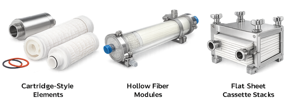
Cartridge and Capsule Assemblies
Cartridges installed in reusable housings require correct seating and sealing. The design should prevent liquid from passing around rather than through the filter element. Risks include:
- Incorrect cartridge length
- Damaged or missing O-rings
- Improper adapter configuration
- Incomplete seating
- Loose housing closure
- Reversed flow direction
- Incorrect vent or drain position
Disposable capsules reduce housing assembly requirements but still depend on correct orientation, secure connections, suitable support, and protection against excessive pressure or mechanical loading.
Hollow-Fiber Modules
Hollow-fiber modules contain multiple small-bore fibers arranged within a housing. Feed may flow through the fiber lumens or around the outside of the fibers, depending on the module design.
Important considerations include:
- Fiber-lumen dimensions
- Module orientation
- Feed and retentate distribution
- Air removal
- Fiber breakage
- Maximum pressure and differential pressure
- Cleaning and storage conditions
- Integrity-test method
- Product recovery from the module and headers
Flat-Sheet Cassette Systems
Flat-sheet cassettes are commonly assembled in a holder using specified compression or torque. Incorrect compression can produce leakage, bypass, gasket damage, flow maldistribution, or permanent cassette deformation.
The assembly procedure should define, as applicable:
- Cassette type and orientation
- Number of cassettes
- Gasket arrangement
- Holder configuration
- Compression or torque requirement
- Tightening sequence
- Retightening conditions
- Maximum allowable pressure
- Inspection and leak-test requirements
These requirements should be based on the approved equipment and membrane supplier instructions rather than a generic torque value.
Flow Through a Tangential-Flow Module
In tangential-flow filtration, feed moves along the membrane surface. Part of the liquid passes through the membrane as permeate, while the retained stream exits or recirculates as retentate.
Crossflow helps limit accumulation at the membrane surface, but it does not eliminate concentration polarization or fouling. Performance depends on the interaction among crossflow, transmembrane pressure, concentration, viscosity, temperature, membrane properties, and feed composition. The existing image has confusing opposing red arrows labelled as retentate flow. Replace it with one clear feed-to-retentate direction and separate perpendicular permeate arrows.
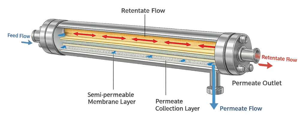
The module drawing should clearly distinguish feed, retentate, and permeate flow. Arrows should not suggest simultaneous flow in conflicting directions unless the diagram is specifically explaining flow distribution within a channel.
Housings, Holders, Manifolds, and Seals
A filter housing or membrane holder provides mechanical support and establishes the pressure boundary around the filtration element. Its design should be appropriate for the operating pressure, temperature, chemicals, installation environment, and cleaning or sterilization method.
Important design features include:
- Pressure and temperature rating
- Compatible product-contact materials
- Filter-element seating
- Closure and locking mechanism
- Vent and drain connections
- Pressure-gauge or transmitter connections
- Integrity-test connections
- Internal surface condition
- Accessibility for assembly and inspection
- Support against piping or hose loads
- Drainability where required by the intended use
The allowable operating envelope should be based on the lowest-rated applicable component, not only the rating of the housing body. Gaskets, hoses, connectors, instruments, disposable assemblies, and filter elements may have lower pressure or temperature limits.
Seals and Gaskets
Seals and gaskets can become direct bypass paths. Their material, dimensions, condition, installation, and compression should be controlled.
Potential failures include:
- Chemical swelling or embrittlement
- Permanent compression
- Incorrect material
- Misalignment
- Pinching or cutting
- Reuse beyond the approved lifecycle
- Incorrect size
- Particulate shedding
- Loss of elasticity after thermal cycling
Where more than one gasket material is used at a facility, identification and storage controls should reduce the possibility of installing the wrong material.
Pumps and Flow Generation
The pump must provide the required flow and pressure without creating unacceptable product damage, temperature increase, pulsation, cavitation, or membrane stress.
Pump selection should consider:
- Required flow and pressure range
- Turndown capability
- Feed viscosity
- Sensitivity of the product to shear
- Potential for gas entrainment
- Accuracy and repeatability
- Cleanability or disposable flow-path requirements
- Pulsation
- Heat generation
- Maximum discharge pressure
- Maintenance requirements
Peristaltic pumps provide product isolation within disposable tubing but can generate pulsation and tubing wear. Diaphragm pumps may provide controlled low-shear transfer but can also produce pulsating flow. Rotary-lobe and centrifugal pumps may be appropriate for some larger-scale applications, subject to process and sanitary-design requirements.
Pump speed should not automatically be treated as equivalent to flow. Actual flow can change with tubing dimensions, tubing wear, viscosity, backpressure, pump-head condition, and system resistance. When flow is critical, it should be measured directly or supported by a justified correlation within the approved operating range.
A blocked downstream path can cause rapid pressure increase. Pressure protection should therefore consider both control-system responses and independent mechanical protection where required by the risk assessment.
Tubing, Piping, Connectors, and Clamps
Tubing and piping affect pressure loss, flow stability, hold-up, cleanability, and product recovery. Their internal diameter and length should be appropriate for the required flow and viscosity. The design should address:
- Tubing collapse under suction
- Expansion or movement under pressure
- Kinking at bends
- Pump-tubing wear
- Unsupported hose loads
- Incorrect connector assembly
- Clamp installation
- Gasket alignment
- Chemical and temperature compatibility
- Maximum pressure rating
- Dead legs or trapped volumes
- Cross-connection risk
Reducing the diameter of a line may decrease hold-up but increase velocity and pressure loss. Increasing the diameter may lower pressure loss but increase system volume. The selected arrangement should balance hydraulic performance, product recovery, and operational practicality.
Single-use assemblies should be adequately supported. Disposable connectors and tubing should not be expected to carry the weight or mechanical load of unsupported instruments, valves, or filled process lines.
Pressure Measurement and Protection
Pressure measurements are used to monitor filter loading, membrane resistance, operating limits, and abnormal conditions.
For a tangential-flow module:
Module pressure drop = Feed pressure − Retentate pressure
A commonly used transmembrane-pressure calculation is:
TMP = ((Feed pressure + Retentate pressure) / 2) − Permeate pressure
The approved calculation convention should match the system design, supplier instructions, and process-development approach. Different configurations may require a different calculation or additional correction.
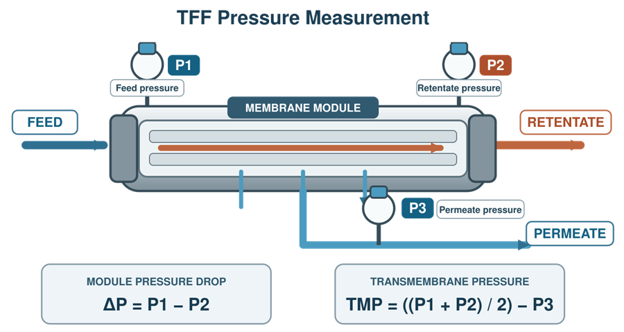
Pressure measurement design should consider:
- Sensor location
- Measurement range
- Accuracy and resolution
- Diaphragm orientation
- Entrapped air
- Liquid-filled impulse lines
- Elevation differences
- Temperature effects
- Cleanability
- Calibration access
- Alarm and interlock setpoints
- Data recording
A pressure transmitter located far from the membrane may not represent the pressure at the module. Small-bore tubing, trapped gas, blocked impulse paths, elevation differences, or poorly located sensors can introduce measurement error.
Alarm and shutdown settings should provide protection before the applicable component limit is exceeded. The relationship among the operating limit, alarm point, shutdown point, sensor accuracy, system response time, and pressure overshoot should be considered.
Software interlocks can reduce risk but do not automatically replace pressure-relief devices or other independent protection where those controls are necessary.
Flow, Volume, and Analytical Measurements
Flowmeters may be installed on feed, recirculation, permeate, retentate, buffer, or diafiltration lines. Selection should consider:
- Flow range and turndown
- Fluid conductivity
- Viscosity
- Entrained gas
- Pulsation
- Line orientation
- Required straight-run conditions
- Accuracy
- Cleanability
- Disposable or reusable installation
- Calibration method
A flowmeter that performs well with water may behave differently with viscous, nonconductive, aerated, or concentrated process fluids.
Other instruments may include:
- Load cells
- Conductivity sensors
- pH sensors
- Temperature sensors
- UV detectors
- Turbidity sensors
- Level sensors
- Bubble or air detectors
Each measurement should have a defined process or control purpose. Instruments used for process decisions, acceptance criteria, material addition, endpoint determination, or protection of critical components should be managed through the applicable calibration and maintenance control program.
Mass-balance calculations can help identify losses, leaks, incorrect routing, unexpected retention, or incomplete recovery. The calculation should account for known hold-up, samples, flushes, waste streams, and measurement uncertainty.
Valve Design and Routing Control
Valves isolate equipment, select flow paths, control pressure, direct permeate or retentate, and support cleaning, flushing, draining, sampling, and integrity testing. Selection should consider:
- Product-contact materials
- Pressure and temperature rating
- Flow-control capability
- Cleanability
- Drainability
- Hold-up volume
- Position indication
- Fail position
- Actuation method
- Maintenance access
- Single-use or reusable configuration
Fail-closed is not universally the safest state. The appropriate fail position depends on the valve function. For example, a valve may need to open to provide a pressure-relief route, while another may need to close to prevent product loss or contamination.
Automated routing should be supported by an approved valve matrix, recipe, or sequence definition. The control system should prevent incompatible paths where incorrect routing could cause bypass, mixing, overpressure, loss of segregation, or discharge to the wrong destination.
Manual valves should be clearly identified and included in operating instructions. Critical manual arrangements may require independent verification before operation begins.
Priming, Venting, and Air Removal
Incomplete wetting or trapped air can reduce effective membrane area, destabilize pressure readings, interfere with integrity testing, interrupt pumping, and affect process performance. The design should provide a practical method for:
- Filling the system
- Wetting the membrane
- Displacing air
- Venting high points where required
- Preventing uncontrolled product discharge
- Confirming complete priming
- Recovering or displacing residual product
Vent requirements depend on the system configuration and intended operation. Vents are not automatically required at every physical high point, but the design should prevent unacceptable trapped gas.
Vents and sample ports should be positioned so they do not create difficult-to-clean branches, contamination risks, or unprotected release paths.
Hold-Up Volume, Drainability, and Product Recovery
Filtration systems can retain product in housings, manifolds, tubing, membrane headers, pump chambers, instruments, sample lines, and low points. Hold-up volume should be evaluated because it can affect:
- Product yield
- Concentration calculations
- Diafiltration-volume calculations
- Flush requirements
- Batch reconciliation
- Cleaning
- Residual carryover
- Maximum hold time
Drainability expectations should be based on intended use. A reusable sanitary system may require controlled drainage after cleaning, while a disposable assembly may rely on air displacement, gravity, or a defined recovery procedure.
Fixed slope values should not be applied automatically to every installation. Required slopes, orientations, and drain points should be justified by system geometry, fluid properties, cleaning strategy, and recovery requirements.
Cleaning, Sanitization, Sterilization, and Storage
Not every filtration system is designed for clean-in-place or steam-in-place operation. The required approach depends on the membrane, housing, process, contamination risk, and reuse strategy. For reusable systems, the design should support the approved sequence for:
- Product recovery
- Pre-rinsing
- Cleaning-agent circulation
- Contact time and temperature
- Intermediate rinsing
- Final rinsing
- Sanitization
- Drying or wet storage
- Storage-solution removal
- Pre-use conditioning
Cleaning conditions must remain within the compatibility limits of the membrane, seals, instruments, and other product-contact components.
Where steam sterilization is used, the system should allow air removal and condensate drainage and should protect components from excessive temperature, pressure, vacuum, or differential pressure. Steam compatibility should be established for the complete assembly, not inferred from the stainless-steel housing alone.
Cleaning validation requirements are separate from equipment design. Design features can support reproducible cleaning, but they do not by themselves demonstrate acceptable residue removal.
Single-Use and Reusable Components
Single-use assemblies can reduce cleaning requirements and changeover effort, but they introduce different controls. These may include:
- Supplier assembly specifications
- Sterilization documentation
- Lot traceability
- Packaging integrity
- Expiration or shelf-life control
- Shipping and storage conditions
- Extractables and leachables evaluation
- Assembly inspection
- Connection and disconnection controls
- Pressure limitations
- Disposal requirements
Reusable systems require controls for cleaning, inspection, preventive maintenance, seal replacement, surface condition, storage, and cumulative component exposure.
A hybrid system may combine reusable pumps, instruments, and supports with a disposable product-contact flow path. The boundary between disposable and reusable components should be defined so that responsibility for calibration, maintenance, cleaning, and batch documentation is clear.
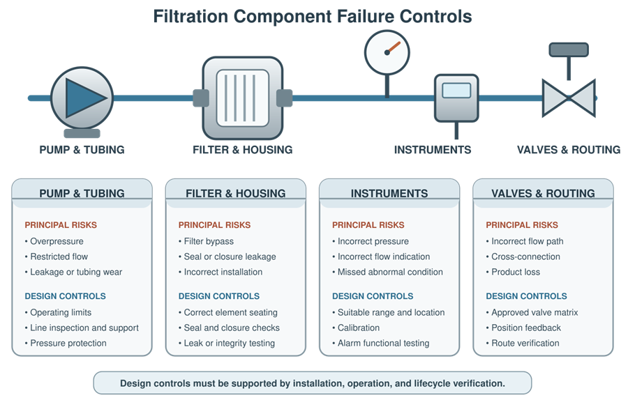
Component-Level Failure Controls
| Component | Example failure | Potential consequence | Example control |
|---|---|---|---|
| Filter or membrane | Fouling, rupture, incorrect type or orientation | Reduced flow, altered retention, contamination or product loss | Material verification, operating limits, pressure monitoring and approved installation |
| Housing or holder | Incomplete closure, damage or incorrect compression | Leakage or bypass | Assembly procedure, inspection, torque or compression control and leak testing |
| Gasket or seal | Wrong material, damage or misalignment | Bypass, leakage or chemical incompatibility | Part identification, inspection and replacement requirements |
| Pump | Excessive speed, wear, cavitation or tubing failure | Pressure excursion, flow instability, shear or leakage | Operating limits, alarms, maintenance and pressure protection |
| Tubing or piping | Kink, collapse, blockage or wrong connection | Restricted flow, overpressure or incorrect routing | Line sizing, physical support, inspection and connection verification |
| Pressure instrument | Drift, trapped air or poor location | Incorrect TMP or failure to detect overpressure | Suitable installation, calibration and functional testing |
| Flowmeter | Incorrect range or sensitivity to gas or viscosity | Incorrect flow control or material addition | Appropriate technology, calibration and operating-range verification |
| Valve | Wrong position, leakage or actuator failure | Bypass, product loss or cross-connection | Valve matrix, position feedback, sequence control and verification |
| Vent or sample port | Open path, poor closure or contamination | Loss of containment or contamination | Controlled design, cap or valve verification and operating procedure |
The table provides examples only. The actual failure assessment should reflect the system configuration and intended process.
Supplier Documentation and Design Verification
Supplier documentation can support component selection and lifecycle control. Depending on the component, useful documentation may include:
- Product and model identification
- Material certificates
- Product-contact material declarations
- Pressure and temperature ratings
- Dimensional drawings
- Surface-finish information
- Membrane specifications
- Retention or bacterial-challenge information
- Extractables data
- Sterilization certificates
- Recommended installation instructions
- Cleaning and compatibility information
- Calibration certificates
- Software and firmware information
- Preventive-maintenance recommendations
- Spare-parts lists
Supplier documentation should be reviewed for applicability to the purchased configuration. A general brochure should not be treated as evidence for a specific material, rating, or performance claim.
Design verification should confirm that selected components meet the approved requirements and are mutually compatible. Particular attention should be given to interfaces between components supplied by different vendors.
Lifecycle Control
Component performance can change through wear, repeated cleaning, thermal cycling, chemical exposure, calibration drift, software changes, or replacement with a different model or material. Lifecycle controls should address:
- Approved component specifications
- Unique identification where required
- Installation and replacement records
- Calibration status
- Preventive maintenance
- Spare-part equivalence
- Membrane and seal reuse limits
- Inspection criteria
- Storage conditions
- Supplier changes
- Obsolescence
- Periodic review
- Change control
Maintenance strategy is addressed further in preventive maintenance and equipment reliability. Changes to filters, membranes, tubing, pumps, instruments, software, materials, suppliers, or operating ranges should be assessed through change-control impact assessment.
Relationship to Qualification and Process Validation
Equipment qualification should demonstrate that the installed filtration system and its critical components conform to approved requirements and operate as intended across the qualified ranges. Qualification may include verification of materials, installation, instruments, alarms, interlocks, pump operation, valve routing, pressure protection, data recording, cleaning functions, and defined operating sequences.
Detailed qualification strategy is addressed in filtration skid qualification and lifecycle control.
Qualification does not by itself establish that a manufacturing filtration step consistently achieves its process objective with the actual product or process stream. Filter capacity, microbial retention, clarification performance, product recovery, concentration, diafiltration, virus clearance, and acceptable reuse may require process-specific validation or supporting studies.
These process applications are addressed in bioprocess filtration validation: clarification, TFF, and virus filtration.
Regulatory Context
Pharmaceutical filtration equipment should be appropriately designed, sized, located, constructed, cleaned, maintained, and controlled for its intended use. Applicable requirements include the equipment provisions in 21 CFR Part 211, Subpart D.
Automated and computerized functions should also be controlled in accordance with the applicable requirements for automatic, mechanical, and electronic equipment. Process validation expectations are described in the FDA guidance Process Validation: General Principles and Practices.
For aseptic applications, filtration-system design should also be evaluated within the contamination-control and sterile-processing strategy described in the FDA guidance Sterile Drug Products Produced by Aseptic Processing—Current Good Manufacturing Practice.
Conclusion
A filtration system is only as reliable as the components and interfaces that establish its flow path, pressure boundary, separation function, measurement capability, and contamination controls.
Effective design requires coordinated selection of the membrane, module, housing, pumps, tubing, seals, valves, instruments, vents, drains, and control functions. Component specifications should reflect the intended process, and identified failure modes should be addressed through design, operating controls, qualification, calibration, maintenance, and change control.
A well-designed system supports qualification and process validation, but it does not replace either activity.