

Lyophilization System Qualification and Lifecycle Control
Purpose and Scope
Lyophilization system qualification demonstrates that an installed pharmaceutical freeze-dryer is properly designed, installed, configured, and capable of operating reproducibly throughout its intended mechanical, thermal, vacuum, refrigeration, stoppering, cleaning, sterilization, automation, and data-recording ranges.
Qualification establishes equipment capability independently of a specific product formulation. Product-specific cycle performance is addressed separately in lyophilization process qualification and continued verification.
This article covers:
- Qualification planning and system boundaries
- User requirements and design qualification
- Supplier documentation, FAT, and SAT
- Installation qualification
- Operational qualification
- Equipment-level performance verification
- Automation and computerized-system controls
- Cleaning, SIP, and aseptic interfaces
- Acceptance criteria and deviations
- Release to GMP use
- Calibration and maintenance integration
- Change control, periodic review, and requalification
The lyophilizer’s design and critical components are described in pharmaceutical lyophilizer design and critical components.
Qualification Lifecycle and Scope
Qualification should follow the approved equipment lifecycle:
- Intended-use and GMP-impact assessment
- User Requirements Specification
- Design review and Design Qualification
- Supplier assessment
- Factory Acceptance Testing
- Site Acceptance Testing and commissioning
- Installation Qualification
- Operational Qualification
- Equipment-level performance verification, where separately defined
- Final review and release
- Routine operation, calibration, and maintenance
- Change control and periodic review
- Event-driven requalification
- Controlled retirement
The exact division among commissioning, IQ, OQ, and equipment-level PQ may vary by site procedure. The important requirement is that all applicable requirements and risks are verified with traceable evidence. Changing the protocol label does not eliminate a required test.
The qualification lifecycle establishes equipment capability before product-specific process qualification begins.
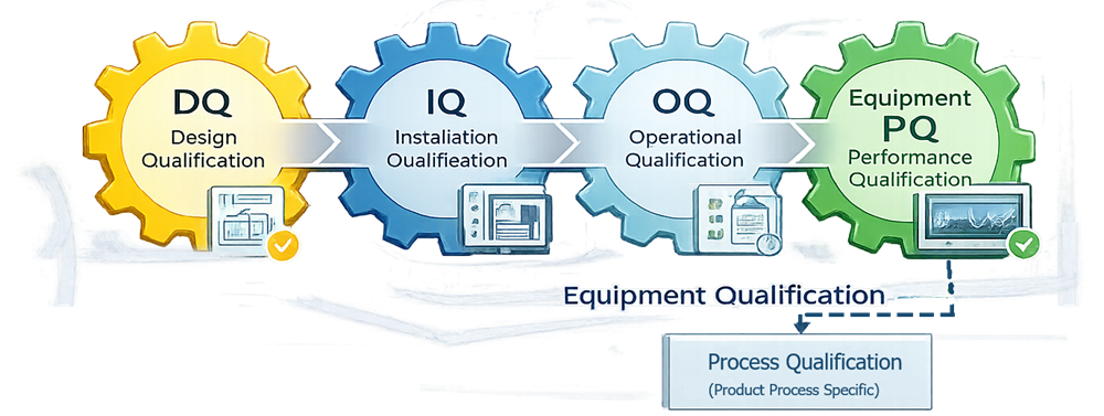
Equipment Qualification Versus Process Qualification
The qualification plan should explicitly separate equipment testing from product-specific process validation.
| Equipment qualification | Process qualification |
|---|---|
| Confirms lyophilizer capability | Confirms product-cycle reproducibility |
| Based on URS and design requirements | Based on formulation and process-development knowledge |
| Uses engineering tests, mapping instruments, and simulated loads | Uses the intended product, container closure, load pattern, and commercial cycle |
| Verifies shelf, vacuum, condenser, stoppering, automation, CIP, and SIP functions | Verifies critical quality attributes and critical process parameters |
| Establishes the qualified equipment operating range | Establishes the validated product-specific process |
| May include water or suitable surrogate loads | Normally includes commercial-scale product batches |
A successfully qualified lyophilizer is not automatically suitable for every product or cycle. Product formulation, vial size, fill volume, stopper, load density, freezing behavior, critical product temperature, vapor load, and drying endpoint remain product-specific considerations.
Similarly, acceptable finished-product results cannot replace documented verification that the lyophilizer performs according to its approved requirements.
Qualification Planning and System Boundaries
The qualification plan should define the system being qualified and identify supporting systems covered by separate qualification packages.
The lyophilizer boundary may include:
- Product chamber and doors
- Shelf stack and thermal-fluid system
- Condenser and vapor duct
- Refrigeration equipment
- Vacuum pumps and control valves
- Pressure and temperature instruments
- Stoppering mechanism
- Sterile vent and backfill-gas assemblies
- CIP and SIP components
- Defrost and drainage systems
- Loading and unloading equipment
- PLC, HMI, recipe management, and historian
- Local electrical and control panels
- Interfaces with filling-line, isolator, RABS, facility, and utility systems
Separately qualified supporting systems may include:
- Electrical distribution
- Cooling water
- Chilled water
- Clean steam
- Purified water or water for injection
- Compressed air
- Nitrogen or sterile process gas
- Facility automation
- Aseptic filling and transfer equipment
- Environmental-control systems
- Site data infrastructure
The plan should define how supporting-system evidence will be referenced and how integrated interfaces will be tested.
User Requirements and Design Qualification
The URS establishes the approved basis for lyophilizer design, procurement, qualification, and release. Requirements should be specific, testable, and traceable.
Typical requirements address:
- Intended products and container types
- Maximum and minimum load configurations
- Number, size, and spacing of shelves
- Shelf-temperature operating range
- Heating and cooling ramp capability
- Temperature-control accuracy and uniformity
- Chamber-pressure operating range
- Vacuum pull-down and leak-rate performance
- Condenser minimum temperature
- Total ice capacity
- Peak vapor-capture capability
- Stoppering travel and load
- Sterile-gas backfill
- Chamber cleaning and sterilization
- Loading and unloading configuration
- Alarm and interlock functions
- Electronic records and data retention
- User access and audit trails
- Utility requirements
- Maintenance and calibration access
- Materials and surface finishes
- Documentation and supplier support
General URS principles are addressed in URS for GMP facilities, utilities, and equipment.
Design Qualification
Design Qualification should confirm that the proposed lyophilizer design satisfies approved requirements and adequately controls identified risks.
DQ may include review of:
- General arrangement drawings
- Piping and instrumentation diagrams
- Chamber and condenser design
- Shelf construction and thermal-fluid distribution
- Refrigeration calculations
- Vacuum-system sizing
- Condenser ice capacity and sublimation-rate capability
- Vapor-path conductance
- Stoppering design
- Cleaning and sterilization boundaries
- Chamber drainage
- Sterile-gas filtration
- Loading and unloading interfaces
- Instrument ranges and accuracy
- Alarm and interlock strategy
- Automation architecture
- Electronic-record controls
- Utility loads
- Maintenance access
- Spare parts and obsolescence risks
Design deficiencies should be resolved or formally controlled before relying on installation or operational testing. Broader DQ principles are described in Design Qualification for GMP systems and equipment.
Supplier Documentation, FAT, and SAT
Supplier Documentation
The supplier package should provide sufficient information to install, operate, maintain, qualify, and control the lyophilizer throughout its lifecycle.
Documentation may include:
- Approved specifications
- Design drawings
- Pressure-vessel certificates
- Material certificates
- Surface-finish records
- Weld documentation
- Instrument and valve lists
- Electrical schematics
- Software and hardware inventories
- Functional specifications
- Control narratives
- Alarm and interlock lists
- Recipe parameter definitions
- Calibration certificates
- Operating and maintenance manuals
- Recommended spare-parts lists
- Refrigeration documentation
- Cleaning and sterilization instructions
- Supplier test records
Supplier records may support qualification after documented assessment, but supplier testing should not be accepted solely because it was performed by the manufacturer.
Factory Acceptance Testing
FAT should verify selected functions before shipment, when deficiencies can be corrected more efficiently.
FAT may cover:
- Equipment configuration
- Chamber and shelf construction
- Control-system operation
- HMI displays
- Recipe functions
- Alarm and interlock logic
- Instrument communication
- Valve sequencing
- Shelf movement
- Stoppering operation
- Data collection
- User-access functions
- Documentation completeness
Tests requiring final utilities, field installation, or site integration normally require repetition or confirmation during SAT or qualification.
Site Acceptance Testing
SAT and commissioning confirm that the installed equipment is ready for formal qualification. Activities may include:
- Start-up and basic operation
- Utility availability
- Rotation and direction checks
- Valve and instrument checks
- Communication verification
- Refrigeration start-up
- Vacuum-system start-up
- Door and stoppering movement
- Initial leak testing
- Safety-system verification
Commissioning records may be leveraged when the test was approved, controlled, traceable, executed with suitable instruments, and reviewed according to the validation plan.
Installation Qualification
IQ confirms that the installed lyophilizer conforms to approved design documentation and supplier requirements.
Equipment Identification and Configuration
IQ should document:
- Manufacturer
- Model
- Serial number
- Equipment identification
- Chamber and condenser configuration
- Shelf quantity and dimensions
- Refrigeration package
- Vacuum-pump configuration
- Stoppering-system configuration
- Control-system hardware
- Installed software and firmware versions
Mechanical Installation
Verification should address, as applicable:
- Chamber and door installation
- Shelf-stack alignment
- Stoppering bellows
- Condenser and vapor duct
- Vacuum piping
- Refrigeration connections
- Thermal-fluid piping
- CIP and SIP piping
- Vent and backfill-gas assemblies
- Drain slopes and low points
- Valve orientation
- Safety and relief devices
- Equipment anchoring
- Maintenance access
Utilities
Utility verification should confirm:
- Correct utility connection
- Identification and labeling
- Approved operating range
- Isolation provisions
- Flow direction
- Pressure and temperature ratings
- Alarm interfaces
- Drainage
- Utility release or qualification status
Potential utilities include electrical power, cooling water, chilled water, compressed air, clean steam, process gas, purified water, water for injection, and facility exhaust.
Materials and Surface Documentation
IQ should confirm required documentation for:
- Product-contact materials
- Sterile-boundary materials
- Gaskets and elastomers
- Internal surface finish
- Welds
- Lubricants
- Thermal fluid
- Cleanability and compatibility
Instrumentation
The installed-instrument inventory should identify:
- Instrument tag
- Manufacturer and model
- Serial number
- Measurement range
- Calibration range
- Accuracy
- Location
- Control, alarm, or recording function
- Calibration status
Critical instruments commonly include shelf-temperature sensors, condenser-temperature sensors, capacitance manometers, Pirani gauges where provided, process-gas instruments, sterilization sensors, and shelf-position feedback.
Automation Baseline
IQ should establish the approved computerized-system baseline, including:
- PLC and HMI hardware
- Software and firmware versions
- Network configuration
- Input/output lists
- Recipe database
- Alarm database
- User-role configuration
- Audit-trail configuration
- Historian and report configuration
- Time synchronization
- Backup configuration
- Remote-access controls
Installation verification does not establish functional performance. Functions documented during IQ must still be challenged during OQ when they affect process control, product quality, safety, or data integrity.
Operational Qualification
OQ demonstrates that the lyophilizer operates as intended throughout its defined engineering ranges and under applicable challenge conditions.
The OQ strategy should be based on:
- Approved requirements
- Design documentation
- Risk assessment
- Supplier testing
- Intended operating range
- Critical failure modes
- Process-development needs
- Automation and data-integrity requirements
Operating Modes and Sequences
Testing should cover applicable modes such as:
- Start-up
- Standby
- Manual operation
- Automatic cycle operation
- Freezing
- Primary-drying simulation
- Secondary-drying simulation
- Vacuum break
- Gas backfill
- Stoppering
- Defrost
- CIP
- SIP
- Shutdown
- Aborted-cycle recovery
- Restart after utility interruption
Mode transitions should occur only when defined permissives are satisfied.
Shelf-Temperature Control
OQ should verify:
- Low, intermediate, and high temperature setpoints
- Setpoint accuracy
- Steady-state stability
- Cooling ramp rates
- Heating ramp rates
- Overshoot and undershoot
- Shelf inlet and outlet response
- Recovery after a setpoint change
- Alarm and interlock functions
Acceptance criteria should reflect the approved URS and intended process range rather than a generic industry limit.
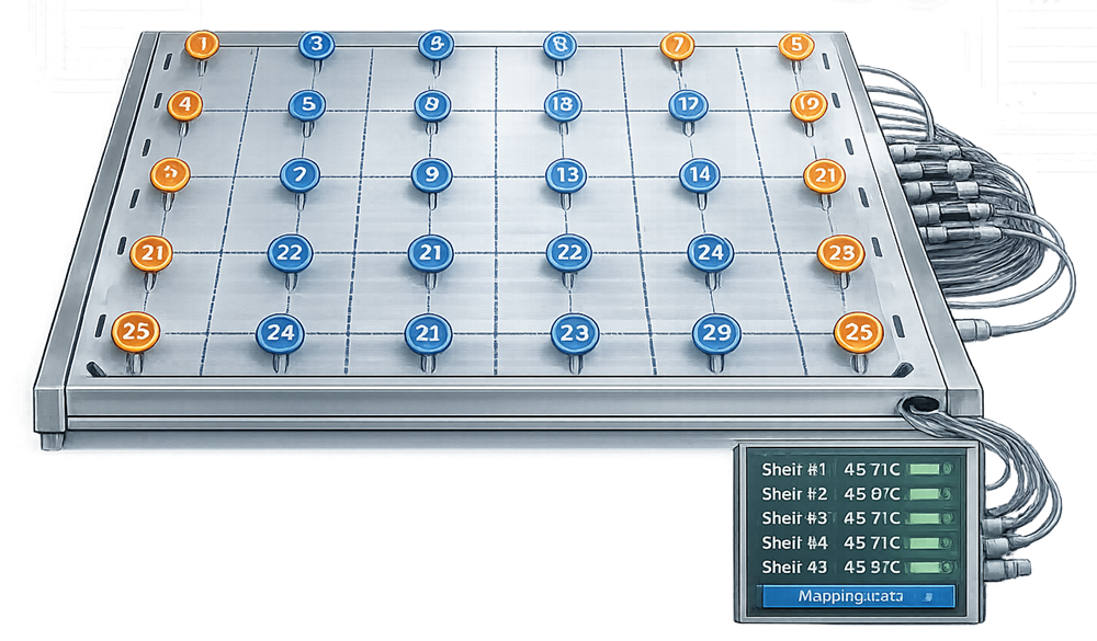
Shelf-Temperature Mapping
Shelf mapping determines temperature distribution within and among shelves at defined operating conditions.
The study should address:
- Sensor quantity and placement
- Edge, center, front, and rear positions
- Upper, middle, and lower shelves
- Mapping-instrument accuracy
- Stabilization criteria
- Test setpoints
- Data-acquisition interval
- Intra-shelf variation
- Shelf-to-shelf variation
- Hot and cold locations
- Repeatability where required
Empty-chamber shelf mapping is normally an equipment-capability test and may be performed during OQ. Loaded or simulated-load studies may be added when needed to evaluate integrated equipment behavior.
Vacuum and Pressure Qualification
Vacuum Pull-Down
The pull-down test should verify:
- Initial chamber condition
- Time to reach defined pressure
- Pump and valve response
- Stability after reaching the target
- Repeatability
- Alarm behavior
- Performance across applicable pressure ranges
Pressure-Control Stability
Pressure control should be challenged at representative low, intermediate, and high setpoints.
Evaluation may include:
- Deviation from setpoint
- Oscillation
- Overshoot
- Control-valve response
- Recovery following disturbance
- Behavior during controlled gas bleed
- Stability during simulated vapor load
A capacitance manometer is commonly used as the gas-independent pressure-control reference. Where a Pirani gauge is installed, testing should confirm its expected response and data recording. A fixed numerical agreement between the two instruments should not be imposed across all drying conditions because the Pirani response depends on gas composition.
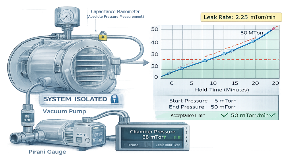
Chamber Leak-Rate Test
A rate-of-rise test evaluates the pressure increase after the chamber reaches a defined vacuum and is isolated from the active vacuum system.
A simple calculation is: Rate of pressure rise=t2−t1P2−P1
Where:
- P1 is chamber pressure at the beginning of the measurement interval.
- P2 is chamber pressure at the end of the interval.
- t2−t1 is the defined measurement duration.
The procedure should define:
- Initial chamber temperature
- Initial chamber pressure
- Stabilization period
- Isolation configuration
- Measurement duration
- Pressure instrument
- Units
- Acceptance limit
- Treatment of temperature-related outgassing
The observed pressure rise may include actual leakage, outgassing, and vapor released from residual moisture. The test should therefore be performed under controlled and reproducible conditions.
Condenser and Refrigeration Qualification
Condenser testing should verify more than the lowest attainable temperature.
Tests may include:
- Shelf cooling performance
- Condenser pull-down
- Minimum condenser temperature
- Temperature stability
- Refrigeration-stage transitions
- Compressor sequencing
- Alarm and trip functions
- Recovery following disturbance
- Defrost sequence
- Meltwater drainage
- Simulated ice load
- Simulated peak vapor load
Total condenser ice capacity and peak vapor-capture rate are different requirements. A condenser may hold the total expected ice mass but still fail to control pressure during the period of maximum sublimation.
Any simulated-load method should be scientifically justified and safely executed. The study should define how the selected challenge represents the intended commercial demand.
Stoppering, Venting, and Backfill Qualification
Stoppering verification should evaluate:
- Shelf-stack alignment
- Vertical travel
- Position feedback
- Mechanical travel limits
- Compression consistency
- Stopper seating height
- Vial tipping
- Stopper tilt
- Vial breakage
- Repeatability across shelf locations
- Operation at the intended chamber pressure
- Recovery from an interrupted sequence
Testing should use representative or justified surrogate vials and stoppers.
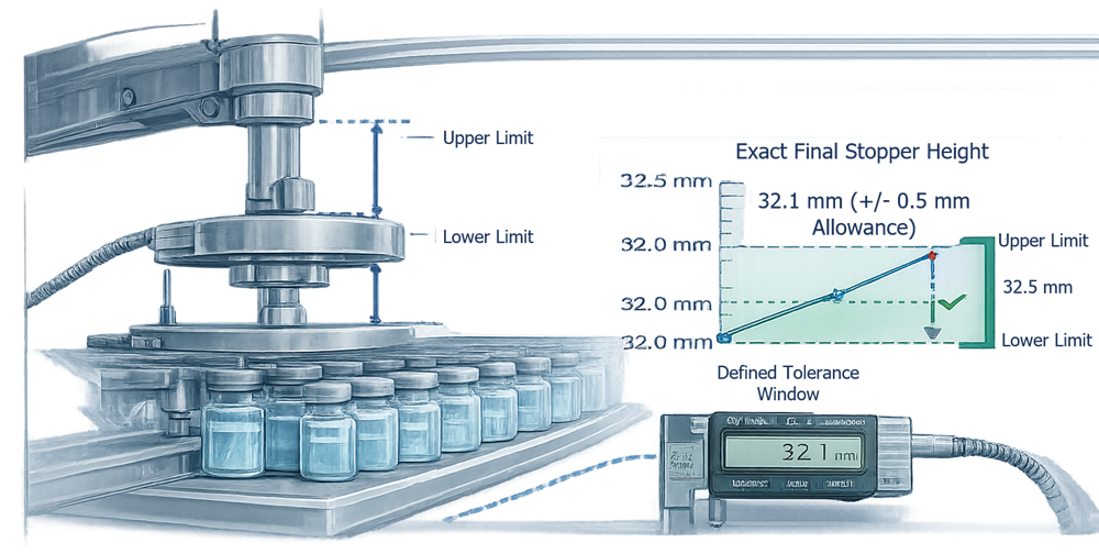
The test demonstrates mechanical stoppering capability. It does not by itself establish container-closure integrity for every product and container system. Related downstream controls are addressed in stoppering, capping, and sealing system qualification.
Vacuum-break and gas-backfill testing should confirm:
- Gas-supply availability
- Filter installation and status
- Valve sequencing
- Backfill rate
- Final pressure
- Overshoot
- Alarm response
- Prevention of uncontrolled venting
- Batch-record capture
CIP, SIP, and Sterile-Boundary Qualification
Where automated cleaning or sterilization is included, qualification should define the boundary and identify which functions are tested within the lyophilizer package.
CIP Functions
Functional qualification may include:
- Recipe execution
- Spray-device operation
- Flow, pressure, temperature, and time
- Detergent addition
- Rinse sequencing
- Valve operation
- Chamber and condenser drainage
- Alarm challenges
- Data recording
CIP functional qualification demonstrates that the equipment delivers the defined cleaning sequence. It does not replace the site’s product-residue and cleaning-validation evidence. General architecture and lifecycle controls are addressed in CIP utility systems.
SIP Functions
SIP qualification may include:
- Air removal
- Heat-up
- Steam-pressure control
- Temperature distribution
- Exposure time
- Condensate removal
- Drain operation
- Cold-location identification
- Post-cycle drying
- Sterile venting
- Sterile hold
- Alarm and abort logic
The sterile boundary may include the chamber, condenser, vapor duct, vent filters, backfill lines, drains, valves, and instruments. Boundary limits should be shown on an approved diagram.
Detailed sterilization-cycle qualification is addressed in SIP utility systems.
Alarm, Interlock, and Failure Testing
Critical alarms and interlocks should be challenged under controlled conditions. Testing may include:
- High or low shelf temperature
- Chamber-pressure deviation
- Vacuum loss
- Condenser-temperature deviation
- Refrigeration failure
- Thermal-fluid circulation failure
- Vacuum-pump failure
- Sterile-gas pressure loss
- Door-position disagreement
- Valve-position disagreement
- Stoppering failure
- CIP or SIP deviation
- Instrument-signal failure
- Network interruption
- Data-recording failure
- Power interruption
- Emergency stop
Testing should verify:
- Alarm initiation
- Message accuracy
- Time stamp
- Audible or visible indication
- Equipment response
- Interlock action
- Operator acknowledgment
- Event and audit-trail recording
- Recovery and restart behavior
The expected safe state should be defined for each failure. Immediate shutdown is not necessarily the appropriate response for every fault because uncontrolled loss of vacuum, heating, cooling, or sterile status may create additional product risk.
Automation and Data-Integrity Verification
Lyophilizer automation may require a separate computerized-system validation package, but critical automation functions should remain traceable to the integrated equipment qualification. Verification should address:
- User access
- Role-based permissions
- Recipe creation and approval
- Recipe version control
- Setpoint limits
- Audit trails
- Alarm and event history
- Batch-report generation
- Data completeness
- Time synchronization
- Data export
- Backup
- Restoration
- System restart
- Interface failure
- Remote access
- Configuration control
Electronic data should permit reconstruction of the executed cycle, including:
- Recipe identity and version
- Actual setpoints
- Recorded temperatures and pressures
- Phase transitions
- Manual actions
- Alarms
- Acknowledgments
- Aborts
- Restarts
- Recipe or configuration changes
Applicable electronic-record controls are addressed in 21 CFR Part 11 compliance and checklist.
Equipment-Level Performance Verification
Some sites use the term equipment PQ for integrated testing under representative or simulated operating conditions. Other sites include these tests within OQ. Either approach is acceptable when the scope and rationale are clearly documented.
Equipment-level performance verification may include:
- Representative simulated load
- Maximum shelf loading
- Minimum or partial loading
- Water-filled or justified surrogate containers
- Edge and corner locations
- Long-duration operation
- Integrated shelf and pressure control
- Condenser response under simulated vapor load
- Stoppering with representative components
- Repeated runs
- Interface testing with loading equipment
The purpose is to demonstrate integrated equipment capability—not to establish product-specific critical quality attributes, cycle acceptability, or commercial PPQ.
Empty-chamber shelf mapping should not automatically be classified as equipment PQ. It is ordinarily an engineering-capability test and commonly belongs in OQ. Loaded testing may be used when the load materially affects equipment performance and the test remains independent of a specific product formulation.
Condensed OQ Test Matrix
The legacy eight-column matrix should be replaced with this more readable version.
| Test area | Principal objective | Typical challenge | Required evidence |
|---|---|---|---|
| Operating modes | Verify controlled sequences and transitions | Start-up, run, abort, restart, shutdown | Trends, event logs, observed results |
| Shelf control | Verify temperature range and control | Low, middle, and high setpoints; heating and cooling ramps | Temperature trends and calculations |
| Shelf mapping | Establish uniformity and repeatability | Edge, center, and shelf-to-shelf locations | Mapping report and probe traceability |
| Vacuum pull-down | Verify evacuation capability | Chamber evacuation from defined starting condition | Time-to-pressure and stability data |
| Pressure control | Verify stable control | Multiple pressure setpoints and disturbances | Pressure and valve-position trends |
| Leak rate | Verify chamber integrity | Isolated rate-of-rise test | Pressure-rise calculation |
| Condenser | Verify refrigeration and vapor-capture capability | Minimum temperature and justified simulated load | Temperature, pressure, and load records |
| Defrost and drain | Verify removal of accumulated ice | Complete defrost sequence | Event log and drainage inspection |
| Stoppering | Verify travel and seating | Representative vials and stoppers | Travel and seating measurements |
| Vent and backfill | Verify controlled pressure restoration | Defined gas flow and final pressure | Pressure trend and event record |
| CIP/SIP | Verify functional sequence | Defined cleaning or sterilization cycle | Cycle data and alarm challenges |
| Alarms and interlocks | Verify fault detection and response | Forced critical failure conditions | Alarm and interlock records |
| Power-loss response | Verify controlled safe state and recovery | Approved interruption simulation | Event, recovery, and data review |
| Electronic records | Verify complete and protected data | Representative cycle and configuration change | Batch report, audit trail, backup evidence |
Acceptance Criteria
Acceptance criteria should be:
- Approved before execution
- Traceable to requirements or risk controls
- Quantitative where technically appropriate
- Applicable to the tested operating range
- Supported by engineering or process rationale
- Clear enough to produce an objective pass/fail decision
Potential sources include:
- Approved URS
- Design specifications
- Supplier performance specifications
- Process-development needs
- Engineering tolerances
- Risk assessments
- Historical data from comparable systems
- Applicable regulatory requirements
Acceptance criteria should not be revised after execution merely to accommodate an unexpected result. A technically unjustified result requires deviation assessment, not retrospective normalization.
Results Near an Acceptance Limit
A passing result close to a limit may still warrant evaluation when it indicates:
- Limited equipment capability
- Measurement uncertainty
- Progressive deterioration
- Insufficient operating margin
- Sensitivity to environmental or utility variation
- Poor repeatability
Passing the numerical limit does not automatically eliminate the need for engineering assessment.
Deviations and Qualification Completion
Qualification deviations should document:
- The requirement or test affected
- Description of the observed condition
- Immediate action
- Data and evidence
- Root cause or technical assessment
- Impact on equipment capability
- Impact on other qualification results
- Corrective action
- Retesting requirement
- Residual limitation
- Quality approval
Retesting should not erase the original failure. The qualification record should preserve the initial result, investigation, correction, and successful retest.
The final qualification report should identify:
- Tests completed
- Results and acceptance decisions
- Deviations and investigations
- Outstanding items
- Approved operating ranges
- Calibration and maintenance requirements
- Operational limitations
- Required procedural controls
- Requalification commitments
- Final conclusion regarding fitness for intended use
Formal release should occur only after prerequisites and unresolved risks have been assessed and approved.
Routine Monitoring and Continued Equipment Verification
After release, selected indicators should be monitored to confirm that the lyophilizer remains capable. Potential indicators include:
- Leak-rate results
- Vacuum pull-down time
- Pressure-control stability
- Shelf-temperature deviations
- Ramp performance
- Condenser pull-down time
- Refrigeration alarms
- Cycle interruptions
- Stoppering failures
- CIP or SIP deviations
- Instrument out-of-tolerance events
- Door-seal replacements
- Vacuum-pump performance
- Data gaps
- Audit-trail anomalies
Routine product-cycle data may provide useful equipment information, but product-specific continued process verification remains within the lyophilization process qualification and continued verification lifecycle.
Calibration and Preventive Maintenance
Critical instruments should be managed through the applicable GMP calibration program and metrology control.
Calibration scope may include:
- Shelf-temperature sensors
- Chamber and condenser temperature sensors
- Capacitance manometers
- Pirani gauges where used for GMP decisions
- Sterilization sensors
- Gas-pressure and flow instruments
- Hydraulic pressure instruments
- Portable qualification instruments
Preventive maintenance may include:
- Chamber-door seals
- Valve seals
- Vacuum pumps
- Refrigeration compressors
- Thermal-fluid pumps
- Stoppering bellows
- Hydraulic systems
- Sterile-gas filters
- Refrigerant and thermal-fluid checks
- Drain inspection
- Data-storage and control hardware
Post-maintenance verification should reflect the affected function. General maintenance controls are addressed in preventive maintenance and system reliability.
Change Control and Requalification
Changes should be evaluated before implementation to determine their possible effect on:
- Qualified operating range
- Product cycles
- Sterile boundary
- Chamber integrity
- Temperature uniformity
- Pressure control
- Condenser performance
- Stoppering
- CIP or SIP
- Automation
- Electronic records
- Calibration
- Maintenance
- Regulatory commitments
Potential requalification triggers include:
- Chamber or door repair
- Door-seal design change
- Shelf replacement or mechanical adjustment
- Thermal-fluid pump replacement
- Refrigeration overhaul
- Refrigerant conversion
- Condenser modification
- Vacuum-pump replacement
- Pressure-control-valve replacement
- Capacitance-manometer relocation or change
- Stoppering-system repair
- Bellows replacement
- CIP or SIP modification
- Sterile-gas-system change
- PLC, HMI, or recipe-management modification
- Alarm or interlock change
- Loading-system modification
- Extended shutdown
- Repeated performance deviations
- Adverse trend
- Major relocation
Selecting Requalification Scope
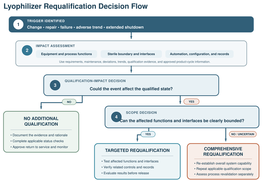
Requalification should be targeted to the changed or potentially affected functions unless the impact cannot be adequately bounded.
| Change or condition | Potential verification |
|---|---|
| Door gasket replacement | Visual inspection and leak-rate test |
| Pressure instrument replacement | Calibration, loop check, pressure-control verification |
| Vacuum-pump replacement | Pull-down, pressure control, alarms, and leak test as applicable |
| Shelf or thermal-fluid repair | Temperature control, ramp testing, and targeted mapping |
| Refrigeration overhaul | Shelf and condenser temperature performance |
| Stoppering adjustment | Travel, alignment, seating, and interlock testing |
| Control-software change | Impacted functional testing, audit trail, data, backup, and regression testing |
| SIP modification | Boundary review, distribution testing, and sterilization requalification |
| Extended shutdown | Readiness assessment with targeted functional verification |
| Unexplained adverse trend | Investigation-driven testing based on suspected failure modes |
A like-for-like replacement does not automatically mean that no verification is required. The assessment should consider installation, calibration, configuration, function, and possible unintended effects.
Periodic Review
Periodic review should determine whether the qualification basis remains current and supported by operating evidence.
Review inputs may include:
- Qualification status
- Changes
- Deviations and investigations
- Alarm and failure trends
- Leak-rate history
- Vacuum and refrigeration performance
- Calibration history
- Out-of-tolerance events
- Maintenance history
- Repeat repairs
- CIP and SIP performance
- Electronic-record issues
- Audit-trail review
- Backup and restoration status
- Supplier notices
- Spare-parts availability
- Hardware and software obsolescence
- Product and load changes
- Requalification activities
- Open CAPA
Possible conclusions include:
- Qualification remains current
- Procedural or maintenance improvements are required
- Targeted requalification is required
- Comprehensive requalification is required
- Product-cycle impact must be assessed
- Equipment replacement or retirement planning is required
Periodic review does not replace event-driven change assessment. Significant changes and failures should be evaluated when they occur.
Transition to Process Qualification
Equipment release establishes that the lyophilizer is capable of operating within approved engineering limits. It does not authorize every product cycle.
Before product-specific qualification begins, confirm:
- Equipment qualification is approved
- Critical deviations are closed
- Calibration is current
- Preventive maintenance status is acceptable
- Approved operating ranges are documented
- Recipes are controlled
- Electronic records are functional
- Required cleaning and sterilization cycles are validated
- Utilities are released
- Load and container configurations are defined
- Analytical methods are ready
- Process-development knowledge is available
The subsequent lyophilization process qualification and continued verification should remain within the qualified equipment operating range or document and resolve any identified gap.
Summary
Lyophilization system qualification establishes documented evidence that the freeze-dryer is correctly installed and capable of controlling shelf temperature, chamber pressure, condenser performance, refrigeration, stoppering, cleaning, sterilization, automation, and electronic records throughout its intended range.
Lifecycle control continues after initial release through calibration, maintenance, performance monitoring, change assessment, periodic review, and risk-based requalification. Equipment qualification and product-specific process validation are connected, but they remain separate evidence packages.