

Chromatography Skid Design, Architecture, and Process Control
Chromatography skids are integrated purification systems that control fluid delivery, column loading, washing, elution, product collection, regeneration, sanitization, and associated electronic records. Their performance depends on coordinated mechanical, fluidic, instrumentation, automation, and data-management functions.
The chromatography column provides the separation medium, but the skid establishes the conditions under which separation occurs. Flow stability, pressure control, buffer composition, valve sequencing, sensor performance, fraction-routing logic, and management of air or residual fluids can directly affect product recovery, impurity clearance, peak resolution, and batch consistency.
Purpose and Lifecycle Position
This article addresses the design, architecture, functionality, and process-control strategy of chromatography skids used in pharmaceutical and biopharmaceutical manufacturing.
It covers:
- System boundaries and process interfaces
- Buffer and feed delivery
- Pumping and hydraulic control
- Valve-manifold and flow-path architecture
- Column interfaces
- Inline instrumentation
- Fraction collection and diversion
- Recipe and phase control
- Alarms, permissives, and interlocks
- Electronic records and data interfaces
- Cleaning, sanitization, and storage interfaces
- Single-use and reusable configurations
- Design documentation and lifecycle control
Detailed chromatography media behavior, column preparation, packing, regeneration, storage, and reuse are addressed in Chromatography Column Phases and Maintenance.
Formal DQ, IQ, OQ, equipment-level PQ, software testing, release, and requalification are addressed in Chromatography System Qualification.
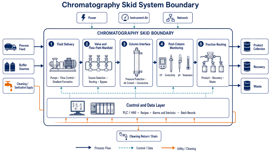
Chromatography Skid System Boundary
The system boundary should be defined from intended use rather than from the physical skid frame alone.
A typical chromatography skid boundary may include:
- Feed and buffer inlet connections
- Pumps and pulsation-control devices
- Bubble traps, air sensors, and degassing provisions
- Flow meters and control valves
- Pressure instruments
- Valve manifolds and transfer tubing
- Gradient-generation or buffer-blending functions
- Column inlet and outlet connections
- UV, conductivity, pH, and temperature instruments
- Fraction-selection and diversion valves
- Product, waste, recovery, and cleaning outlets
- Clean-in-place or sanitization connections
- Single-use assemblies and their interfaces
- Local control panel, PLC, HMI, and recipe configuration
- Interfaces with historians, manufacturing systems, or electronic batch records
- Instrument air, electrical power, network, drain, and utility connections
The chromatography column may be included within the equipment boundary, managed as a connected process component, or controlled under a separate column-lifecycle program. The selected approach should be documented consistently in requirements, drawings, risk assessments, qualification records, calibration records, and operating procedures.
External buffer vessels, product hold vessels, CIP systems, filtration skids, and manufacturing information systems should be identified as interfaces even when they are qualified separately.
Functional Architecture
A chromatography skid normally contains five interacting functional layers:
- Fluid supply and conditioning
- Pumping and hydraulic control
- Valve routing and column interface
- Process measurement and endpoint detection
- Automation, data acquisition, and batch control
A weakness in one layer can affect the entire purification step. Accurate sensors cannot compensate for incorrect valve routing, and a correct recipe cannot compensate for an unstable pump, trapped air, or an unsuitable flow path.
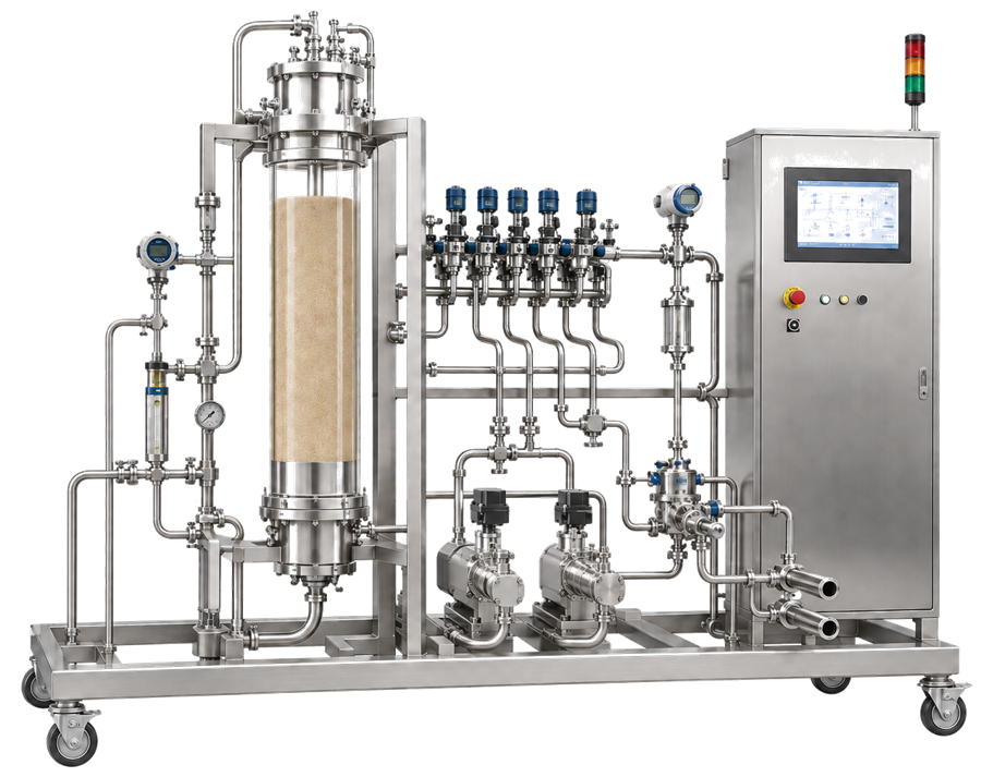
Buffer and Feed Supply
The inlet section receives process feed, equilibration buffer, wash buffer, elution buffer, regeneration solution, sanitizing solution, storage solution, or water, depending on the process and equipment configuration. Design considerations include:
- Number and identification of inlet connections
- Prevention of incorrect source connection
- Buffer compatibility with wetted materials
- Available inlet pressure or suction head
- Buffer temperature
- Management of vessel depletion
- Prevention and detection of air entrainment
- Line-clearance and flushing requirements
- Hold-up volume between the source and column
- Cross-connection and backflow prevention
- Sampling requirements
- Connection of reusable or single-use transfer assemblies
Where the skid performs inline buffer blending or gradient formation, the design must also control component ratios, mixing performance, conductivity or pH response, and the delay between mixture formation and arrival at the column.
Pumps and Flow Control
Chromatography skids commonly use positive-displacement or other low-shear pump technologies selected for the required flow range, pressure capability, turndown, chemical compatibility, and product characteristics. The pumping system should support:
- Accurate flow throughout the approved range
- Stable low-flow operation
- Controlled acceleration and deceleration
- Acceptable pulsation
- Protection against dry running
- Prevention of cavitation
- Controlled response to increasing column backpressure
- Appropriate flow direction
- Reproducible delivery during gradient operation
- Safe shutdown without damaging the column or losing product unnecessarily
Flow may be controlled using pump speed, a flow-control loop, pressure limitations, or coordinated pump-and-valve logic.
Flow-regime assumptions should not be generalized. Tubing diameter, viscosity, flow rate, fittings, packed-bed resistance, and operating phase determine the hydraulic conditions. The relevant design objective is controlled and reproducible delivery without unacceptable pressure, mixing, air, or residence-time effects.
Valve Manifold and Flow Paths
Automated valves route fluids through defined process paths. Depending on the design, the manifold may control:
- Feed loading
- Column bypass
- Equilibration
- Washing
- Elution
- Fraction collection
- Waste diversion
- Product recovery
- Column regeneration
- Skid cleaning
- Column sanitization
- Storage-solution circulation
- Drainage
Valve sequencing must prevent incompatible or unintended paths. The control system should not rely only on an output command; critical valves should provide position feedback or another means of confirming the commanded state.
Flow-path design should address:
- Internal and external hold-up volume
- Dead legs and difficult-to-flush locations
- Drainability
- Incorrect cross-connections
- Trapped air
- Mixing between sequential solutions
- Product loss during transitions
- Carryover between batches or products
- Chemical and pressure compatibility
- Accessibility for inspection and maintenance
- Correct installation of replaceable flow-path components
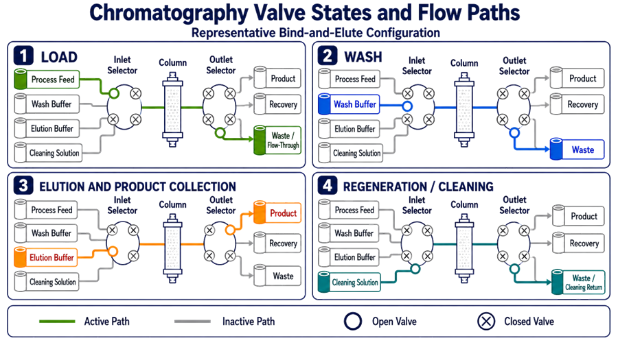
Valve routing changes with each chromatography phase. The illustration below uses a representative bind-and-elute configuration to distinguish the active inlet, column, and outlet path during loading, washing, elution and product collection, and regeneration or cleaning. Inactive routes are shown in gray so that the selected source, open valves, and destination remain clearly identifiable. Actual valve positions, destinations, transition criteria, and failure responses must be defined in the approved piping and instrumentation diagrams, valve matrix, control narrative, recipe configuration, and verified software baseline. Flow-through chromatography and site-specific recovery arrangements may use different routing strategies.
Column Interface and Protection
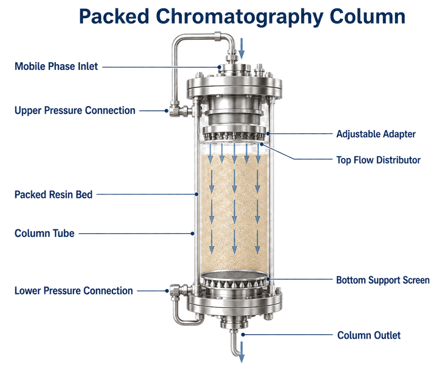
The skid must provide a controlled interface with the chromatography column without introducing excessive pressure, flow disturbance, air, leakage, or contamination.
Design considerations include:
- Column inlet and outlet pressure ratings
- Maximum allowable differential pressure
- Connection size and type
- Column bypass arrangement
- Direction of flow
- Air-removal provisions
- Pressure-relief or protective shutdown strategy
- Secure support for hoses and tubing
- Prevention of mechanical loading on column nozzles
- Compatibility with column packing and unpacking activities
- Column identification and status verification
- Correct association between the selected recipe, column, and resin
Pressure should be evaluated at locations that allow the control system to distinguish among inlet restrictions, column pressure drop, downstream restrictions, and abnormal valve alignment.
A single pressure transmitter may be insufficient when differential pressure across the column is important to equipment protection or process control.
Post-Column Monitoring and Product Routing
The post-column section determines whether material is sent to product collection, an intermediate fraction, recovery, recycle, or waste.
Routing decisions may be based on:
- UV absorbance
- Conductivity
- pH
- Eluted volume
- Time
- Column volumes
- Recipe phase
- Combined sensor conditions
- Operator confirmation where justified
The design should account for the physical delay between the measurement point and the diversion valve. If the detector is located upstream of the valve, the control logic may require a calculated or empirically established delay based on downstream hold-up volume and actual flow rate.
Without this compensation, the skid can detect the correct peak but switch the collection valve too early or too late.
Fraction-routing controls should address:
- Defined collection thresholds
- Baseline and signal stability
- Detector range and saturation
- Noise filtering
- Time or volume delays
- Valve actuation time
- Valve-position confirmation
- Destination-vessel availability
- Vessel identification
- High-level conditions
- Misrouting prevention
- Recovery following a sensor or valve failure
- Traceability of collected and diverted volumes
Product-routing logic should default to a justified safe state. Depending on the process, the safe state may be waste diversion, flow stoppage, or retention in the current route. It should not be assumed that one fail-safe response is correct for every chromatography process.
Instrumentation and Measurement Strategy
Instrumentation should be selected according to the parameter being controlled, the required measurement range, accuracy, response time, installation location, process chemistry, cleaning conditions, and consequences of failure.
| Instrument | Typical purpose | Important design considerations |
|---|---|---|
| Flow meter | Flow monitoring and closed-loop control | Rangeability, accuracy, low-flow performance, orientation and zeroing |
| Inlet pressure transmitter | Detects supply restriction or pump-suction problems | Location, vacuum capability and air or cavitation risk |
| Pre-column pressure transmitter | Protects the column and monitors inlet pressure | Maximum pressure, response time and shutdown logic |
| Post-column pressure transmitter | Supports differential-pressure calculation | Range, elevation effects and downstream restriction |
| UV detector | Detects product or impurity peaks | Wavelength, path length, range, saturation, baseline and lamp status |
| Conductivity sensor | Monitors buffer composition and gradient progression | Temperature compensation, range, response and installation |
| pH sensor | Confirms buffer or process conditions | Calibration, response time, storage, installation and sanitization exposure |
| Temperature sensor | Supports compensation and process interpretation | Location, range and relationship to other measurements |
| Air or bubble detector | Detects air before sensitive equipment or the column | Sensitivity, tubing compatibility, nuisance alarms and response |
| Weight or level signal | Confirms source and destination availability | Interface reliability, scaling and alarm limits |
Sensor location is part of the measurement definition. Two correctly calibrated instruments can produce different results when installed at different hydraulic positions or separated by significant hold-up volume.
Instrumentation should be accessible for calibration, verification, replacement, and inspection without compromising the hygienic boundary. Calibration and maintenance controls are addressed in GMP Instrument Calibration and Lifecycle Control.
Process-Control Strategy
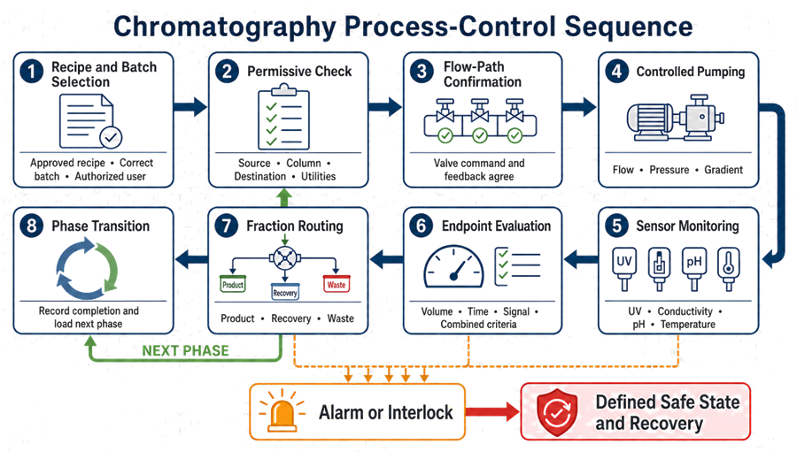
Chromatography control is normally phase-based. A recipe defines the required sequence, parameters, transitions, routing conditions, alarms, and operator interactions.
Typical phases include:
- System preparation and line clearance
- Flow-path priming
- Column equilibration
- Feed loading
- Washing
- Elution
- Product or fraction collection
- Strip or regeneration
- Sanitization
- Storage or shutdown
Not every process uses every phase, and the sequence may differ for bind-and-elute, flow-through, polishing, continuous, or multicolumn chromatography.
Recipe Parameters
Recipe-controlled parameters may include:
- Selected inlet and outlet paths
- Flow rate or linear velocity
- Pressure limits
- Buffer ratio
- Gradient slope or step
- Target conductivity
- Target pH
- Phase volume
- Number of column volumes
- Phase duration
- UV threshold
- Fraction-selection criteria
- Transition delay
- Rinse endpoint
- Cleaning-agent concentration
- Contact time
- Sanitization conditions
Parameters should be classified according to their intended control and approval requirements. Critical parameters, equipment-protection limits, recipe constants, operator-adjustable settings, and engineering settings should not be managed as an undifferentiated list.
Phase Transitions
A phase may end based on:
- Delivered volume
- Number of column volumes
- Elapsed time
- Conductivity endpoint
- pH endpoint
- UV response
- Pressure condition
- Completion of a gradient
- Operator confirmation
- Combination of multiple conditions
The system should define what happens when an endpoint is not achieved within the expected time or volume. Indefinite continuation can consume buffer, expose the column to unsuitable conditions, delay processing, or compromise product recovery.
Permissives, Interlocks, and Alarms
A permissive prevents an operation from starting until required conditions are satisfied. An interlock initiates or enforces a response when an unacceptable condition occurs. An alarm informs the operator that attention is required but does not necessarily stop the process.
| Condition | Typical control response |
|---|---|
| Required source not selected or unavailable | Prevent phase start |
| Incorrect valve alignment | Prevent pumping or redirect to a safe route |
| No confirmed product destination | Prevent collection or divert according to the approved strategy |
| High pre-column pressure | Reduce flow or stop the pump |
| High differential pressure | Stop or hold the phase and protect the column |
| Low inlet pressure | Stop or limit pumping to prevent cavitation or air entry |
| Loss of flow | Alarm, pause phase timing or stop operation |
| Air detected | Stop flow, divert or execute approved air-removal logic |
| UV signal out of range | Alarm and apply the approved fraction-routing response |
| Conductivity or pH outside limits | Alarm, hold, divert or terminate according to recipe logic |
| Valve-command and feedback mismatch | Stop affected routing and prevent phase continuation |
| Destination vessel high level | Stop collection or divert to the approved alternate route |
| Communication failure | Enter a defined safe state and preserve available records |
| Power interruption | Stop safely and support controlled recovery |
Alarm priority should reflect consequence and required response. Excessive low-value alarms can obscure conditions requiring immediate action.
Setpoints, delays, hysteresis, latching behavior, acknowledgement requirements, and recovery actions should be defined and tested. Alarm configuration must remain under change control.
Automation Architecture
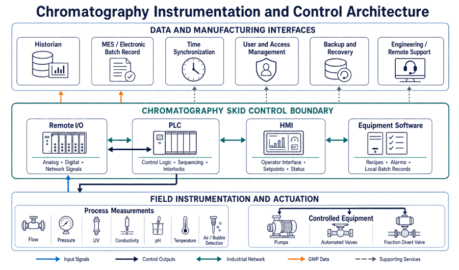
A chromatography skid may use a local PLC and HMI, an industrial computer, a distributed control system, or a vendor-supplied software platform.
The automation boundary may include:
- Controller hardware
- Input and output modules
- HMI
- Recipe database
- User and role configuration
- Alarm database
- Batch reports
- Audit trails
- Local data storage
- Historian interface
- Manufacturing execution system interface
- Time synchronization
- Network infrastructure
- Backup and recovery functions
- Remote-support connection
The control system should maintain clear separation among:
- Operator actions
- Supervisor or recipe-authoring functions
- Maintenance functions
- Automation-engineering functions
- System-administration functions
Shared accounts should not be used where electronic actions or records must be attributable to individuals.
The illustration below separates field instrumentation and controlled equipment from skid-level automation and external data-management interfaces. Process measurements enter through Remote I/O, the PLC executes sequencing, control logic, and interlocks, and the HMI provides the authorized operator interface. Equipment software manages recipes, alarms, and local batch records, while historian, electronic batch-record, time-synchronization, access-management, backup, recovery, and engineering-support functions complete the computerized-system architecture.
Electronic Records and Data Integrity
The chromatography control system may create GMP records such as:
- Executed recipe parameters
- Actual process values
- Phase start and stop times
- Operator actions
- Alarm and acknowledgement records
- Recipe changes
- Manual interventions
- Fraction-collection decisions
- Batch reports
- Audit trails
- Calibration or verification records
- Aborted-run and recovery information
Electronic records used to demonstrate GMP execution must remain complete, accurate, attributable, contemporaneous, original or appropriately preserved, and available throughout the retention period.
Controls should address:
- Unique user identification
- Role-based access
- Audit trails
- Controlled recipe creation and approval
- Prevention of unauthorized overwriting
- Time synchronization
- Secure data transfer
- Backup and restoration
- Record retention
- Human-readable and electronic copies
- Review of critical changes and exceptions
- Management of local data when the network is unavailable
FDA requirements for automatic and electronic equipment are established in 21 CFR 211.68. FDA’s Data Integrity and Compliance With Drug CGMP guidance addresses risk-based controls for reliable and accurate GMP data. Part 11 applicability should be assessed according to the records and signatures maintained electronically.
Broader controls are addressed in Data Governance Strategy for GxP Systems and Access Control and Electronic Signatures.
Hygienic and Mechanical Design
Reusable product-contact systems should support effective cleaning, inspection, sanitization where required, and protection against contamination.
Relevant design attributes include:
- Compatible product-contact materials
- Suitable surface finish
- Hygienic fittings
- Controlled gasket and seal materials
- Drainability
- Minimized dead legs
- Reduced hold-up volume
- Appropriate tubing slope
- Accessible low points
- Controlled sample points
- Prevention of backflow
- Leak detection
- Chemical and temperature compatibility
- Defined pressure ratings
- Segregation of product and nonproduct utilities
Materials should be compatible with process buffers, high- or low-pH cleaning agents, sanitizing agents, storage solutions, temperature, pressure, and expected exposure duration.
Equipment design, construction, cleaning, maintenance, and automatic controls are addressed by 21 CFR Part 211 Subpart D.
Cleaning, Sanitization, and Storage Interfaces
Reusable chromatography skids may require cleaning, sanitization, flushing, and storage cycles. The skid design should support execution and verification of these cycles, but equipment functionality should not be confused with cleaning-process validation.
The design may need to control:
- Correct cleaning-solution source
- Concentration or conductivity
- Temperature
- Flow rate
- Pressure
- Contact time
- Return conditions
- Rinse endpoint
- Complete path exposure
- Drainage
- Storage-solution introduction
- Removal of cleaning or storage solutions before use
A fixed skid may connect to a centralized Clean-in-Place Utility System or perform a locally configured circulation cycle.
Cleaning validation must establish whether the procedure adequately controls residues, cleaning agents, microorganisms, endotoxin where applicable, and cross-contamination. That separate lifecycle is addressed in Cleaning Validation Strategy and Approach.
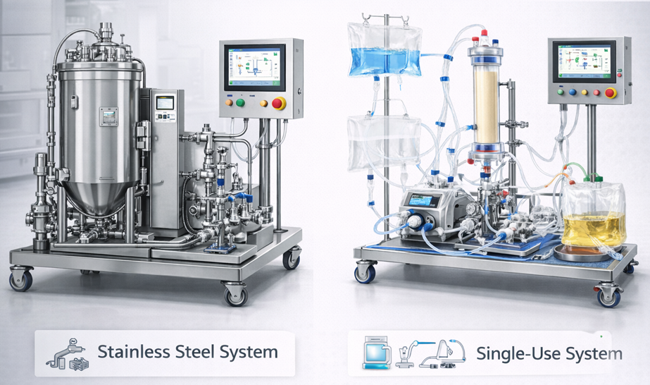
Reusable and Single-Use Configurations
| Design consideration | Reusable stainless-steel system | Single-use system |
|---|---|---|
| Product-contact path | Fixed tubing, valves and instruments | Disposable tubing, bags, connectors and flow cells |
| Cleaning | Requires defined cleaning and rinse strategy | Reduced cleaning scope for discarded product-contact components |
| Sanitization | May be performed in place | Depends on supplied assembly and process requirements |
| Assembly | Fixed installation | Operator assembly or installation of disposable flow path |
| Main contamination risk | Inadequate cleaning or retained residue | Assembly error, breach, damaged component or incorrect part |
| Supplier dependence | Materials and replacement components | Assembly design, irradiation, packaging, lot control and change notification |
| Integrity control | Mechanical inspection and leak testing | Pre-use or post-installation checks where required |
| Change control | Equipment and configuration changes | Supplier, component, assembly and material changes |
| Waste | Cleaning solutions and rinse water | Discarded assemblies and packaging |
| Hold-up volume | Primarily fixed by installed design | May vary with tubing-set configuration and installation |
Single-use technology can reduce cleaning burden but does not eliminate lifecycle control. The program should address:
- Supplier qualification
- Approved component specifications
- Extractables and leachables assessment
- Sterilization status where applicable
- Shipping and storage
- Expiration dating
- Assembly instructions
- Component and lot traceability
- Installation verification
- Connection security
- Leak and integrity risks
- Disposal
- Supplier change notification
- Equivalency of replacement components
Additional controls are addressed in Single-Use Systems in GMP Manufacturing.
Process and Utility Interfaces
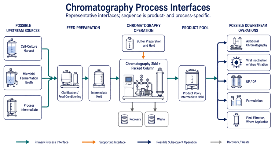
Chromatography does not operate as an isolated skid. Its design must support coordinated transfer from upstream clarification and into downstream concentration, filtration, formulation, or additional purification steps.
Typical interfaces include:
- Clarified harvest or process-feed vessel
- Buffer-preparation and hold systems
- Depth or membrane filtration systems
- Product collection and hold vessels
- Viral-clearance operations
- Ultrafiltration and diafiltration systems
- Cleaning systems
- Waste collection
- Sampling systems
- Manufacturing execution or batch-record systems
The interface definition should address:
- Transfer pressure
- Available flow
- Connection type
- Line identification
- Material status
- Vessel availability
- Vessel capacity
- Process hold time
- Temperature
- Mixing
- Sampling
- Line clearance
- Drainage
- Communication handshake
- Start, stop, and fault behavior
Related membrane-processing architecture is addressed in Filtration and Ultrafiltration System Architecture.
The illustration below positions chromatography as a configurable purification operation rather than one mandatory step in a fixed manufacturing sequence. Conditioned feed may originate from cell-culture harvest, microbial fermentation broth, or another process intermediate. After chromatography, the product pool may proceed to additional chromatography, viral inactivation or virus filtration, UF/DF, formulation, or final filtration where applicable. The actual sequence, hold points, transfer conditions, and control interfaces must be defined for the specific product and manufacturing process.
Design Review and Supplier Documentation
The design review should evaluate whether the proposed skid can satisfy its intended use under normal, maximum, minimum, startup, shutdown, cleaning, maintenance, and failure conditions.
Expected supplier documentation may include:
- Functional and design specifications
- Process and instrumentation diagrams
- General arrangement drawings
- Flow-path drawings
- Valve matrix
- Instrument list
- Component specifications
- Materials and elastomer certificates
- Surface-finish documentation
- Welding documentation where applicable
- Software and hardware architecture
- Input/output list
- Control narratives
- Alarm and interlock list
- Recipe descriptions
- User-role matrix
- Data-flow diagram
- Network requirements
- Backup and recovery instructions
- Calibration requirements
- Maintenance manuals
- Spare-parts recommendations
- Single-use assembly drawings and specifications
- Factory acceptance test documentation
- Software version and configuration records
Supplier documentation should be assessed before acceptance. Its existence does not establish that site requirements have been satisfied.
Design qualification principles are addressed in Design Qualification.
Design Features Affecting Qualification
Design decisions establish the eventual qualification scope. High-impact characteristics commonly include:
- Flow-control accuracy and operating range
- Pressure measurement and column-protection logic
- Gradient-generation performance
- Valve sequencing and position feedback
- Sensor ranges and response times
- Fraction-routing accuracy
- Hold-up volume and transition timing
- Air detection and removal
- Recipe security
- Alarm and interlock behavior
- Electronic-record controls
- Cleaning-path configuration
- Single-use assembly controls
- Utility and system interfaces
- Recovery following interruption or failure
Qualification should demonstrate that the installed system satisfies approved requirements and operates reliably throughout its defined range. It should not be used to compensate for incomplete design definition.
Detailed testing belongs in Chromatography System Qualification.
Lifecycle Control
The approved skid configuration establishes a controlled baseline covering hardware, instruments, software, recipes, alarms, interfaces, flow paths, materials, and operating limits.
Changes requiring documented assessment may include:
- Pump or valve replacement
- Instrument replacement or relocation
- Tubing-size or flow-path changes
- New columns or column dimensions
- New resin or chromatography mode
- Revised pressure or flow limits
- Recipe changes
- Alarm or interlock changes
- Software updates
- Controller or HMI replacement
- Historian or MES interface changes
- New single-use assemblies
- Supplier component substitutions
- Cleaning-agent or sanitization changes
- New product or campaign
- Skid relocation
- Utility changes
The impact assessment should determine whether the change affects equipment qualification, computerized-system validation, cleaning validation, process validation, calibration, maintenance, regulatory commitments, or approved operating procedures.
General change-assessment principles are addressed in Change Control and Validation Impact Assessment.
Common Design and Control Weaknesses
Recurring weaknesses include:
- System boundaries defined only by the physical skid frame
- Insufficient pressure measurement across the column
- Uncontrolled hold-up volume
- Failure to compensate for detector-to-divert-valve delay
- Valve commands without position confirmation
- Recipes containing uncontrolled engineering parameters
- Excessive operator access
- Manual actions not captured in the batch record
- Alarm flooding
- Undefined response to failed process endpoints
- Inadequate air detection
- Inconsistent single-use assembly installation
- Poor drainability
- Inaccessible instruments
- Incomplete data interfaces
- Unverified backup restoration
- Supplier changes not incorporated into site change control
- Confusion between skid qualification and purification-process validation
These weaknesses should be addressed during requirements definition and design review rather than discovered during execution of qualification protocols.
Conclusion
A chromatography skid is an integrated process-control platform, not merely a collection of pumps, valves, and instruments. It must establish reproducible hydraulic conditions, protect the column, control phase transitions, detect process endpoints, route product correctly, preserve reliable electronic records, and support the selected cleaning or disposable-flow-path strategy.
Effective design begins with a clear intended use and system boundary. Mechanical architecture, instrumentation, automation, recipes, alarms, data handling, utilities, and process interfaces must then operate as one controlled system. This design baseline provides the foundation for formal qualification and reliable lifecycle operation.