

Pharmaceutical Parts Washers: Types, Design, and System Architecture
Pharmaceutical parts washers provide controlled cleaning, rinsing, and drying of reusable manufacturing components, utensils, laboratory glassware, product-contact parts, and equipment accessories. They replace or supplement manual cleaning by controlling mechanical action, water quality, cleaning chemistry, temperature, exposure time, load configuration, rinsing, and drying within a defined cycle.
A parts washer should not be selected only by chamber dimensions or nominal load capacity. Suitability depends on the actual components, soils, internal cavities, loading arrangement, required water quality, containment needs, cleaning process, and downstream use. A washer that performs adequately for open stainless-steel utensils may be unsuitable for hoses, hollow components, complex filling-machine parts, laboratory glassware, or equipment used in aseptic processing.
This article addresses washer types, chamber design, hydraulic architecture, racks, utilities, detergent dosing, controls, drying, containment, and equipment selection. Cycle development and cleaning science are covered in Parts-Washer Cycle Development and Cleaning Process Principles. Qualification, load verification, failure testing, lifecycle control, and requalification are addressed in Parts-Washer Qualification and Lifecycle Control.
Regulatory and Design Context
Under 21 CFR 211.63—Equipment Design, Size, and Location, manufacturing equipment must be appropriately designed, adequately sized, and suitably located for its intended use, cleaning, and maintenance.
21 CFR 211.65—Equipment Construction requires product-contact surfaces to be nonreactive, nonadditive, and nonabsorptive to the extent necessary to protect product quality. This requirement applies to the reusable parts being cleaned and to washer surfaces or components that can affect the cleaned load.
21 CFR 211.67—Equipment Cleaning and Maintenance establishes requirements for equipment cleaning, maintenance, cleaning procedures, inspection, and records.
FDA’s CGMP Questions and Answers: Equipment emphasizes that cleaning effectiveness must be supported by data relevant to the equipment’s materials, exact design, operating conditions, and contaminants.
The regulations do not prescribe one washer configuration or cycle. The site must establish that the selected equipment and cleaning process are suitable for the intended loads.
Intended Use and Washer Selection Basis
The intended-use statement should identify:
- Components and utensils to be cleaned
- Component materials
- Maximum dimensions and weight
- Internal cavities, lumens, hoses, and blind surfaces
- Typical and maximum load size
- Product residues and relevant soils
- Dirty hold time
- Required cleaning agents
- Required wash and rinse-water quality
- Required microbial or endotoxin control
- Drying requirements
- Clean hold time
- Loading and unloading areas
- Containment requirements
- Required throughput
- Manual handling limitations
- Required automation and electronic records
- Interfaces with inspection, sterilization, and storage
A load inventory should be developed before washer selection. The inventory should identify component families, photographs or drawings, dimensions, materials, weight, soil type, disassembly requirements, cleaning orientation, and potential difficult-to-clean locations.
A chamber large enough to contain a component does not necessarily provide an effective cleaning configuration. The rack must position the component so that cleaning solution reaches required surfaces, air can escape from cavities, liquid can drain, and the component remains stable during the cycle.
System Architecture
A pharmaceutical parts washer is an integrated system containing the washing chamber, load-handling arrangement, hydraulic circulation loop, chemical-dosing system, heating system, instruments, automation, drain path, and drying system.
Typical functional elements include:
| Element | Function |
|---|---|
| Washing chamber | Contains the load and circulating cleaning fluid |
| Rack, cart, or basket | Positions and restrains components |
| Spray arms and nozzles | Distribute cleaning and rinse fluids |
| Injection manifold | Delivers fluid through dedicated connections to hollow items |
| Sump or reservoir | Collects solution for heating and recirculation |
| Circulation pump | Provides required flow and pressure |
| Strainer or filter | Removes displaced particles from recirculated solution |
| Water inlets | Supply initial wash, intermediate rinse, and final-rinse water |
| Detergent system | Stores and meters cleaning chemicals |
| Heater or heat exchanger | Heats wash or rinse solution |
| Drain system | Directs spent solution to waste, recovery, or treatment |
| Drying system | Circulates filtered heated air or supports vacuum drying |
| Automation system | Executes recipes, controls equipment, manages alarms, and records data |
| Instruments | Measure temperature, pressure, flow, conductivity, level, or other parameters |
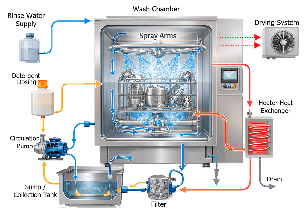
System boundaries should distinguish washer-supplied components from facility utilities and external systems. Interfaces may include:
- Electrical power
- Plant steam or electrical heating
- Purified water
- Water for Injection
- Potable or softened water
- Compressed air
- Heated or HEPA-filtered drying air
- Exhaust
- Drain and neutralization systems
- Detergent storage
- Building automation
- Manufacturing execution or historian systems
Cabinet Parts Washers
Cabinet washers are enclosed batch systems used for cleaning removable manufacturing parts, utensils, trays, containers, change parts, and equipment accessories. Loads are placed on fixed shelves, baskets, racks, or mobile carts inside the chamber.
Mechanical cleaning action is normally delivered by rotating or oscillating spray arms positioned above, below, or beside the load. Some systems include fixed nozzles or dedicated rack connections.
Cabinet washers may use:
- Single-door loading
- Pass-through double-door configuration
- Fixed internal racks
- Removable racks
- Mobile loading carts
- Interchangeable load carriers
- General spray coverage
- Dedicated injection connections
- Combined spray and immersion phases
Selection should account for component size, weight, required orientation, spray access, drainability, operator handling, room layout, and contamination-control strategy.
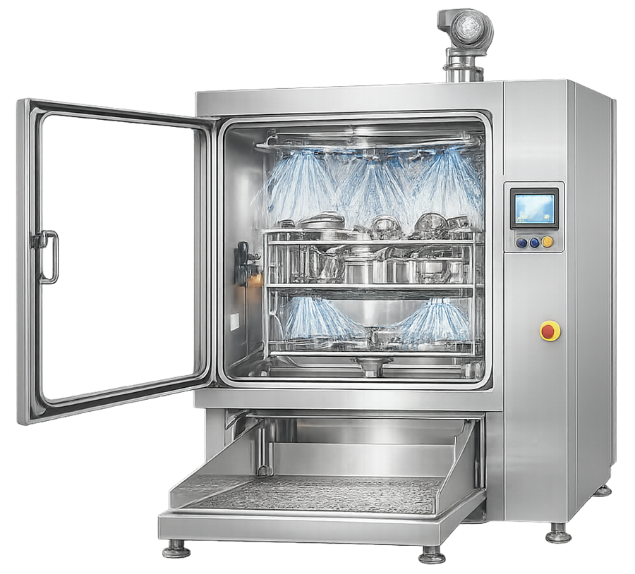
Single-Door Cabinet Washers
Single-door washers are loaded and unloaded from the same side. They may be appropriate when dirty and clean components are handled within one controlled room or when procedural and spatial controls provide adequate segregation.
The design should address:
- Separation of dirty and clean staging
- Equipment status identification
- Prevention of load mix-ups
- Floor drainage
- Detergent handling
- Clean-load protection after unloading
- Traffic patterns
- Operator ergonomics
Pass-Through Washers
Pass-through washers have separate loading and unloading doors and may form part of the physical boundary between dirty and clean areas. Design considerations include:
- Door interlocks
- Room-pressure effects
- Wall sealing
- Prevention of simultaneous door opening
- Dirty-side and clean-side controls
- Cycle-complete indication
- Load-status communication
- Maintenance access
- Exhaust and air balance
- Response to power or control failure
A pass-through washer can support material-flow segregation, but it does not establish decontamination or area separation by itself. The cycle, door controls, installation boundary, and operating procedures must collectively support the intended contamination-control function.
Laboratory Glassware Washers
Glassware washers are designed for bottles, flasks, graduated cylinders, sample containers, and other laboratory vessels requiring internal and external cleaning.
The defining feature is typically an injection rack containing spindles or nozzles that direct cleaning solution into inverted glassware. External spray arms clean the outer surfaces. Design considerations include:
- Number and size of injection positions
- Spindle length and diameter
- Connection of each position to the hydraulic manifold
- Accommodation of different neck sizes
- Drainage of inverted items
- Protection against glass breakage
- Filter or strainer control
- Final-rinse water quality
- Drying through injection paths
- Rack recognition
- Prevention of unused open injection positions
Glassware should not be placed loosely over injection points without a defined loading arrangement. Incorrect height, unstable positioning, blocked spindles, or open unused positions can alter hydraulic distribution and cleaning performance.
A general cabinet washer may clean external glassware surfaces but cannot be assumed to clean narrow internal surfaces unless fluid is delivered into those areas by a qualified arrangement.
Tunnel and Continuous Washers
Tunnel washers move loads through sequential cleaning, rinsing, and drying zones using a conveyor or indexed transport mechanism. Typical stages may include:
- Load entry
- Pre-rinse
- Detergent wash
- Intermediate rinse
- Final high-purity-water rinse
- Air blow
- Heated drying
- Cooling
- Unload or discharge
Tunnel systems support high throughput but introduce more complex control of:
- Conveyor speed
- Zone separation
- Solution carryover
- Countercurrent flow
- Spray-header performance
- Temperature by zone
- Detergent concentration
- Water consumption
- Load spacing
- Entry and exit protection
- Recovery after interruption
A continuous washer should define how residence time is established and how an interrupted load is identified and dispositioned. A conveyor restart must not allow a partially processed load to be treated as successfully completed without appropriate control.
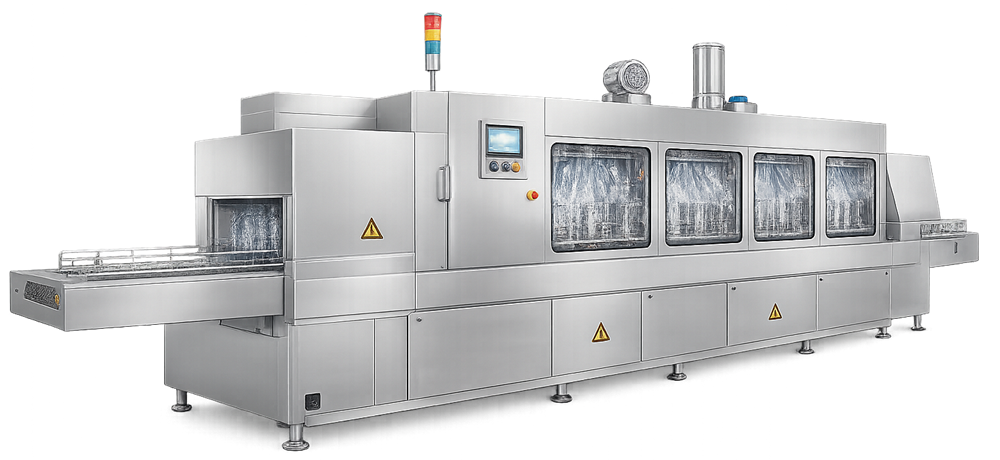
Tunnel washers should be distinguished from vial, ampule, or container washers integrated with aseptic filling lines. Those systems may require additional particulate, endotoxin, sterilization, and aseptic-transfer controls outside the scope of general equipment-parts washing.
Ultrasonic Washers
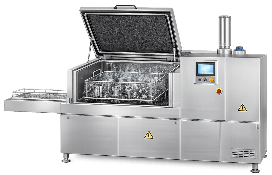
Ultrasonic washers use high-frequency energy to create cavitation within a liquid bath. Formation and collapse of microscopic bubbles can provide cleaning action at surfaces, recesses, joints, and complex geometries that may be difficult to reach with direct spray.
Applications may include:
- Small precision parts
- Filling-machine components
- Laboratory tools
- Nozzles
- Mechanical assemblies
- Components with recesses
- Delicate items unsuitable for high-impact spraying
Performance depends on:
- Ultrasonic frequency
- Power distribution
- Bath volume
- Bath temperature
- Cleaning chemistry
- Gas content
- Load size and position
- Basket design
- Distance from transducers
- Component geometry
- Soil characteristics
- Exposure time
Ultrasonic activity may not be uniform throughout the bath. Dead zones, overloaded baskets, contact between parts, changes in liquid level, or failure of individual transducers can reduce performance.
Ultrasonic washing is not automatically a complete cleaning process. Components may require pre-rinsing, detergent exposure, post-rinsing, high-purity final rinsing, and controlled drying. Ultrasonic cleaning may also be used as a preliminary step before a cabinet-washer cycle.
The existing filename contains a spelling error. It can remain unchanged to avoid unnecessary replacement of the current media reference.
Immersion and Agitated-Bath Washers
Immersion washers clean components within a tank containing water or cleaning solution. Mechanical action may be provided by:
- Solution circulation
- Pumped agitation
- Component movement
- Basket oscillation
- Air agitation
- Ultrasonic energy
Immersion can expose complex external surfaces but may retain displaced soil within the bath. The design should address solution replacement, filtration, bath-life limits, loading density, carryover, draining, and subsequent rinsing.
Shared-bath operation requires assessment of whether soil or residue from one load can contaminate another. A bath should not be reused based only on elapsed time when soil loading, product identity, or chemical condition materially affects suitability.
Clean-Out-of-Place Systems
Clean-out-of-place systems clean removable parts outside their installed process equipment. The cleaning arrangement may combine:
- Pre-rinse station
- Manual disassembly
- Soak tank
- Ultrasonic unit
- Cabinet washer
- Rinse station
- Drying cabinet
- Inspection area
- Protected clean storage
The system boundary includes transfer and handling between these stages. Cleaned components can be recontaminated by uncontrolled carts, gloves, work surfaces, air exposure, poor drainage, or incorrect storage.
The design should support a logical flow from dirty receipt through cleaning, inspection, drying, status identification, and protected storage.
Chamber Design and Construction
The washer chamber must withstand repeated exposure to water, cleaning chemicals, elevated temperature, pressure from spray systems, and drying conditions. Design considerations include:
- Compatible materials
- Smooth internal surfaces
- Rounded transitions
- Cleanable welds
- Drainable chamber floor
- Accessible sump
- Minimal crevices and ledges
- Door-gasket design
- Spray-accessible corners
- Internal lighting where required
- Inspection windows where useful
- Protection of instruments and heaters
- Access for maintenance
The chamber should not retain water, detergent, or displaced residue after cycle completion. Sumps, filter housings, pumps, drain valves, and connected piping should be included in the washer’s self-cleaning strategy.
Doors should provide repeatable sealing while allowing inspection and replacement of gaskets. Door pockets, hinges, locking mechanisms, and gasket channels should not create uncontrolled contamination reservoirs.
Spray-System Architecture
Spray distribution may use:
- Rotating spray arms
- Oscillating spray arms
- Fixed spray headers
- Directed nozzles
- Rack-mounted nozzles
- Injection spindles
- Dedicated hose connections
- Combined chamber and rack circuits
Important design variables include:
- Pump flow and pressure
- Nozzle size
- Number of open nozzles
- Spray-arm rotation
- Spray pattern
- Distance to load surfaces
- Rack restriction
- Simultaneous circuit demand
- Filter or strainer condition
- Return backpressure
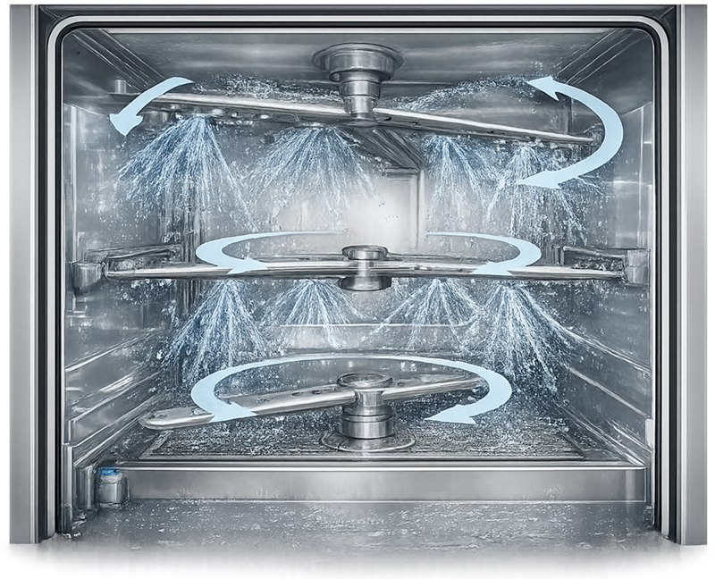
Spray-arm rotation may be driven by fluid reaction rather than a separate motor. A partially blocked nozzle can change rotation speed and spray distribution while the pump continues to operate. Where spray-arm performance is critical, the design should allow direct or indirect verification of rotation.
Flow or pump pressure measured at one location does not prove equal distribution to every nozzle. Hydraulic balance depends on rack configuration, open injection positions, restrictions, and simultaneous use of multiple circuits.
Rack and Load-Carrier Design
Racks are part of the cleaning system, not merely material-handling accessories. Their design determines component position, separation, internal exposure, drainage, and stability.
Racks should:
- Hold components in defined positions
- Maintain separation
- Prevent nesting and stacking
- Avoid contact damage
- Expose critical surfaces
- Orient cavities for air displacement
- Promote drainage
- Prevent movement during washing
- Support safe loading and unloading
- Remain compatible with cleaning agents and temperatures
- Be identifiable and configuration controlled
Dedicated racks, fixtures, or validated loading arrangements may be necessary for complex parts, hoses, vessels, filling-machine components, and product-contact assemblies. Each item should be separated, securely positioned, drainable, and directly exposed to the cleaning spray. General baskets may be suitable for simple utensils when the validated loading pattern prevents stacking, spray shadowing, liquid retention, and movement during the cycle.
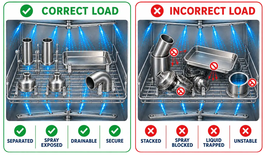
Maximum load should be defined by more than total weight or basket volume. It may require limits on:
- Number of components
- Component family
- Rack position
- Component orientation
- Use of injection connections
- Permitted combinations
- Maximum density
- Maximum hydraulic restriction
- Maximum soil load
Validated loading patterns are addressed further in Parts-Washer Qualification and Lifecycle Control.
Cleaning-Performance Factors
Washer performance depends on interaction among mechanical action, chemistry, temperature, time, water quality, and load configuration.

These relationships are developed in detail in Parts-Washer Cycle Development and Cleaning Process Principles. At the design stage, the washer must provide sufficient adjustable range and measurement capability to support cycle development.
The design should distinguish:
- Equipment operating range
- Cycle-development range
- Qualified range
- Validated cleaning range
- Routine recipe setpoint
- Alarm or failure limit
A washer may be mechanically capable of operating at a temperature or duration outside the validated cleaning range. Equipment capability and approved process conditions are not interchangeable.
Water Supply and Recirculation
Parts washers may use different water qualities for different phases. A cycle might use lower-grade water for an initial wash and Purified Water or Water for Injection for the final rinse, depending on the intended load and subsequent use.
The water strategy should define:
- Water quality for each phase
- Minimum supply pressure
- Required supply temperature
- Maximum fill time
- Required volume
- Final-rinse quality
- Sampling or monitoring provisions
- Backflow prevention
- Control of stagnant branches
- Shutdown and restart requirements
The circulation system may include:
- Sump or reservoir
- Circulation pump
- Heater or heat exchanger
- Strainer
- Fine filter
- Spray circuits
- Rack manifold
- Temperature instrument
- Pressure or flow instrument
- Conductivity instrument
- Return path
Recirculation conserves water and chemicals but redistributes displaced soil throughout the active circuit. Filtration, solution replacement, phase sequencing, and drain logic should control redeposition.
Strainers and filters should be accessible for inspection and replacement. Their loading can affect flow and spray distribution. The control strategy should address blockage, missing elements, incorrect installation, and breakthrough.
Detergent Storage and Dosing
Cleaning chemicals may be supplied from:
- Integrated containers
- Day tanks
- Bulk chemical systems
- Central distribution
- Replaceable containers
- Manually prepared solutions
The dosing system may include:
- Chemical container or tank
- Suction lance
- Dosing pump
- Flow or stroke verification
- Level detection
- Concentration measurement
- Injection point
- Flush connection
- Containment
- Chemical-identification control
Design should prevent use of the wrong chemical and should provide control of:
- Chemical identity
- Concentration
- Dosing quantity
- Injection timing
- Empty-container condition
- Pump failure
- Blocked line
- Leakage
- Operator exposure
- Line flushing
- Chemical expiration or storage condition
Detergent concentration should not be inferred only from pump run time unless pump delivery, chemical strength, solution volume, and system conditions are sufficiently controlled.
Conductivity may support concentration control when a documented relationship exists for the specific chemical, water quality, concentration, and temperature range.
Heating and Temperature Control
Wash and rinse solution may be heated by:
- Electric immersion heaters
- Steam heat exchangers
- Jacketed reservoirs
- External recirculation heaters
- Direct steam injection where appropriate
The design should address:
- Heating capacity
- Heat-up time
- Temperature uniformity
- Control response
- Sensor location
- Minimum solution level
- High-temperature protection
- Low-temperature alarm
- Steam or heater failure
- Thermal-fluid leakage
- Maximum component temperature
- Cooling before unloading
Exposure time should be based on the required in-condition temperature rather than beginning automatically when heating starts.
Temperature requirements should account for both residue removal and component compatibility. Excessive temperature can denature proteins, bake residues onto surfaces, damage polymers, deform parts, or reduce detergent performance.
Rinsing and Endpoint Control
Rinsing removes loosened soil and cleaning-agent residues. Washer design may support:
- Fixed-volume rinses
- Timed rinses
- Multiple rinse phases
- Once-through final rinse
- Conductivity-based endpoint
- pH-based endpoint
- Comparison with supply-water condition
- Final-rinse sampling
Conductivity or pH can support endpoint control only when the measurement is suitable for the cleaning agent and expected residues. A return to supply-water conductivity does not necessarily demonstrate absence of every product residue.
The rinse system should minimize carryover from the wash phase. Relevant features include complete drain steps, fresh-water displacement, clean valve sequencing, sump geometry, and control of retained solution in pumps, filters, racks, and piping.
Drying and Moisture Control
Drying may be performed using:
- Heated recirculated air
- Once-through heated air
- HEPA-filtered air
- Injection drying through rack connections
- Vacuum-assisted drying
- Air blow followed by passive drying
The required endpoint depends on component geometry, downstream use, storage duration, and microbial-control strategy.
Design considerations include:
- Air quality
- Air temperature
- Flow distribution
- Drying time
- Internal drying of hollow items
- HEPA filter access and monitoring
- Condensate management
- Exhaust control
- Component temperature at unloading
- Prevention of recontamination
A dry chamber does not demonstrate that hoses, cavities, inverted vessels, or shielded surfaces are dry. Load orientation and dedicated air paths may be necessary.
Claims that drying prevents microbial growth should be qualified. Drying reduces retained moisture that could support microbial proliferation, but effectiveness depends on the actual dryness achieved, subsequent handling, and storage conditions.
Single-Door, Pass-Through, and Area Integration
Washer installation should support material flow, personnel safety, cleaning-chemical handling, maintenance, and clean-load protection.
Room and facility considerations include:
- Dirty and clean staging space
- Cart movement
- Door swing
- Equipment-service access
- Utility-panel access
- Floor slope and drainage
- Exhaust and heat load
- Chemical containment
- Noise
- Operator lifting and reach
- Wall sealing
- Pressure cascade
- Clean-side protection
- Emergency egress
For pass-through systems, maintenance access should not undermine the intended dirty-to-clean boundary. Service panels, ceiling penetrations, exhaust paths, and equipment voids should be assessed as part of installation design.
Containment Applications
Parts contaminated with potent compounds, sensitizers, hormones, cytotoxic materials, or biological agents may require contained loading, washing, and unloading.
Containment features may include:
- Closed transfer containers
- Bag-in or contained docking
- Negative-pressure chamber operation
- Controlled exhaust
- HEPA filtration
- Decontaminable exterior surfaces
- Closed chemical dosing
- Effluent containment
- Safe filter change
- Door interlocks
- Wash-down of chamber interfaces
Containment and cleaning have different objectives. A washer may remove residue from parts while allowing unacceptable operator exposure during loading or unloading. Conversely, a contained system may protect operators without demonstrating adequate residue removal.
Effluent characterization and disposal should consider product hazards, cleaning chemicals, temperature, pH, and local treatment-system capability.
Automation and Control Architecture
Automated washers commonly use a programmable logic controller and human-machine interface to execute recipes and control:
- Water filling
- Sump level
- Circulation pump
- Spray circuits
- Detergent dosing
- Heating
- Wash and rinse timing
- Drain valves
- Drying
- Door locks
- Alarms and interlocks
- Cycle records
The functional design should address:
- User roles and access
- Recipe creation and approval
- Recipe selection
- Parameter limits
- Rack or load identification
- Operating modes
- Manual controls
- Sequence transitions
- Phase-completion logic
- Alarm handling
- Cycle interruption
- Power-loss recovery
- Data recording
- Report generation
- Backup and restoration
- Software and configuration control
Failure conditions may include:
- Low water level
- Failed fill
- Low circulation pressure
- No spray-arm rotation
- Heater failure
- High temperature
- Detergent container empty
- Dosing failure
- Drain failure
- Door unlocked
- Instrument failure
- Exhaust failure
- Drying-air failure
- Power or communication loss
The design should define whether each condition produces an alarm, phase hold, cycle abort, safe shutdown, or another response. A completed cycle indicator should not be generated when a critical phase failed or was bypassed.
Electronic Records and Data Integrity
Cycle records may support equipment release and cleaning validation. The record should identify:
- Washer
- Recipe and revision
- Rack or load configuration
- Operator
- Start and completion time
- Actual sequence
- Phase duration
- Temperature
- Detergent dosing
- Relevant pressure or flow
- Conductivity or endpoint data
- Alarms
- Manual interventions
- Repeated or skipped phases
- Final cycle status
Where electronic records are used for GMP decisions, the design should address access control, audit trails where required, time synchronization, data retention, backup, restoration, and review of abnormal cycles.
A cycle summary should reflect actual execution rather than only the programmed recipe.
Maintainability and Self-Cleaning
The washer must not become a contamination source. Design should support inspection and cleaning of:
- Chamber
- Sump
- Spray arms
- Nozzles
- Rack manifolds
- Pumps
- Strainers and filters
- Chemical lines
- Door gaskets
- Drain valves
- Drying ducts
- Condensate paths
- Instrument connections
Maintenance access should allow safe inspection without uncontrolled disassembly. Spray arms and racks should be identifiable so replacement with a different configuration is detectable.
The system should define how it is cleaned after maintenance, extended shutdown, chemical change, or use with an unusually difficult soil.
Design Documentation
The design package may include:
- User requirements specification
- Intended-use statement
- Load inventory
- Component drawings or photographs
- Approved load families
- System-boundary drawing
- Process and instrumentation diagram
- General arrangement
- Chamber and rack drawings
- Hydraulic calculations
- Spray-system specifications
- Utility requirements
- Chemical-dosing design
- Instrument and alarm lists
- Functional specification
- Software and configuration records
- Materials and surface documentation
- Electrical drawings
- Drain and exhaust requirements
- Operating and maintenance manuals
- Recommended spare parts
Documentation should be obtained before qualification begins. Missing rack drawings, hydraulic data, software baselines, alarm lists, or instrument specifications can prevent traceability between the intended cleaning process and the installed equipment.
Design Review and Selection
A multidisciplinary design review should evaluate:
- Completeness of the load inventory
- Washer type and chamber size
- Load handling and ergonomics
- Rack and injection requirements
- Spray distribution
- Hydraulic capacity
- Water-quality strategy
- Chemical dosing
- Heating and rinsing
- Drying
- Materials and cleanability
- Containment
- Single-door or pass-through installation
- Automation and records
- Maintenance access
- Facility utility capacity
- Drain and effluent requirements
- Qualification testability
- Supplier documentation
Selection should be based on the most difficult approved loads and operating conditions rather than on an easily cleaned demonstration load.
Relationship to Qualification and Cleaning Validation
Washer qualification demonstrates that the equipment is installed correctly and can control and record its required functions. Testing may include spray operation, hydraulic performance, temperature control, dosing, recipes, alarms, interlocks, drying, data records, and failure response.
Cleaning validation demonstrates that an approved washer cycle consistently cleans defined component loads to established acceptance criteria. The broader residue-control and study strategy is addressed in Cleaning Validation Approach.
Neither qualification nor cleaning validation should begin without an adequate load inventory and controlled loading configurations. A washer cannot be considered generally validated for any component that physically fits inside the chamber.
Conclusion
Pharmaceutical parts-washer suitability depends on the relationship among washer type, chamber architecture, spray distribution, rack design, load geometry, water quality, cleaning chemistry, temperature, rinsing, drying, automation, containment, and facility integration.
Cabinet, glassware, tunnel, ultrasonic, immersion, and clean-out-of-place systems serve different purposes. No configuration is universally appropriate.
A complete load inventory and requirements-based design provide the foundation for controlled cycle development, defensible qualification, cleaning validation, routine cycle review, and lifecycle control.