

Solid Dosage Inspection and Reject Systems: Qualification and Lifecycle Control
Solid dosage inspection systems detect defined defects, contaminants, dimensional variations, weight deviations, missing components, or other unacceptable conditions during manufacturing and packaging. When a nonconforming unit is detected, the associated reject system must remove it from the accepted product stream and maintain segregation through final disposition.
Inspection does not replace control of the manufacturing process. A vision system can reject a visibly damaged tablet but cannot correct the compression condition that caused the damage. A checkweigher can identify mass variation but cannot directly determine active-ingredient content. A metal detector can detect specified metallic test standards but cannot demonstrate the absence of every possible foreign material.
Qualification must therefore address the entire detection-and-rejection chain: product presentation, sensing, measurement or classification, decision logic, tracking, rejection, reject confirmation, containment, electronic records, and line response.
Purpose and scope
This article addresses:
- Metal detectors
- Dynamic checkweighers
- Automated vision-inspection systems
- Manual inspection stations
- Tablet dedusters as inspection-support equipment
- Product conveyors and presentation systems
- Detection thresholds and inspection recipes
- Automated reject mechanisms
- Reject confirmation and reject-bin controls
- Challenge testing
- Electronic records and data integrity
- URS, DQ, supplier documentation, FAT, SAT, IQ, OQ, and equipment-level PQ
- Routine verification, periodic review, change control, and requalification
The article focuses on tablets, hard capsules, and related solid dosage units. Container, closure, label, serialization, and package-leak inspection may use similar principles but require packaging-specific requirements.
Position within solid dosage manufacturing
Inspection equipment may be installed after:
- Tablet compression
- Tablet dedusting
- Capsule filling
- Tablet coating
- Capsule polishing
- Metal detection
- Product transfer
- Primary packaging
- Secondary packaging
The illustration below shows a representative line with tablet compression, dedusting, metal detection, vision inspection, coating, packaging, and checkweighing.
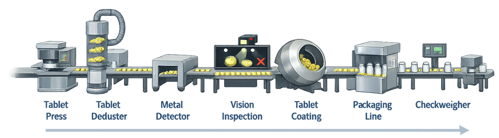
The actual sequence depends on the product, identified defects, equipment configuration, contamination risks, and packaging process. Installing an inspection device at an unsuitable location may reduce detection capability or permit new defects to occur after inspection.
Inspection-system boundaries
The inspection-system boundary may include:
- Product infeed
- Conveyor
- Product-spacing and orientation devices
- Guides
- Encoder
- Trigger sensor
- Metal-detector aperture
- Dynamic weighing conveyor
- Cameras
- Lenses
- Lighting
- Background surfaces
- Image-processing controller
- Inspection software
- Product recipes
- Detection thresholds
- Reject-decision logic
- Tracking delay
- Reject actuator
- Reject confirmation
- Reject bin
- Bin-presence and bin-full sensors
- Bin lock
- Accepted-product discharge
- Line-control interfaces
- Electronic records
- Network and data interfaces
The boundary should include every component required to prove that a detected defective unit is removed and cannot re-enter the accepted stream.
Intended use and defect classification
The intended use should define exactly what the system is required to detect, measure, classify, or reject.
Potential defect categories include:
- Critical defects affecting patient safety or product identity
- Major defects affecting function, dose delivery, integrity, or compliance
- Minor or cosmetic defects
- Process signals used for monitoring but not automatic rejection
Examples may include:
- Metallic contamination
- Missing or broken tablets
- Chipped or cracked tablets
- Capsule splits
- Empty or underfilled capsules
- Color variation
- Incorrect embossing
- Foreign product
- Incorrect dimensions
- Weight outside approved limits
- Missing package components
- Surface contamination
Terms such as “detects defective tablets” are insufficient for qualification. The defect type, size, location, contrast, orientation, frequency, and applicable product conditions should be defined.
Metal-detection systems
Pharmaceutical metal detectors generate and monitor an electromagnetic field. A conductive contaminant passing through the detection aperture alters the field and generates a detection signal.
Metal-detection capability is influenced by:
- Metal type
- Contaminant size
- Shape
- Orientation
- Alloy
- Product composition
- Product temperature
- Product moisture
- Aperture size
- Product position
- Line speed
- Electrical interference
- Equipment vibration
- Detector settings
Ferrous, nonferrous, and stainless-steel test standards are commonly used because their detection behavior differs.
The absence of a signal from one test-piece type does not establish equivalent sensitivity to all metals, shapes, or orientations.
Metal-detector challenge testing
The illustration below shows a conveyor metal detector challenged with ferrous, nonferrous, and stainless-steel test standards.
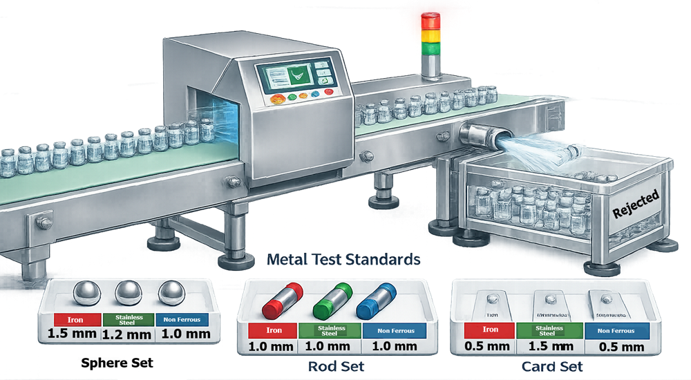
The challenge program should define:
- Test-standard material
- Certified or verified test-standard size
- Test-piece identification
- Product carrier or holder
- Challenge position
- Challenge orientation
- Line speed
- Detector recipe
- Reject response
- Test frequency
- Required response to failure
Challenges may be performed at positions expected to be more difficult for detection, such as different locations across the aperture or within the product stream.
A challenge test is a functional verification of detection and rejection. It should not automatically be called calibration. Calibration is a separate activity performed according to the approved instrument or equipment procedure.
Dynamic checkweighers
Dynamic checkweighers measure units while they move across a weighing conveyor. Units outside approved limits may be rejected automatically.
Applications may include:
- Tablet or capsule gross weight
- Filled-capsule weight
- Bottle or blister weight
- Detection of missing components
- Container count verification
- Package completeness
Checkweigher performance is affected by:
- Conveyor speed
- Product spacing
- Product stability
- Vibration
- Air movement
- Static charge
- Belt condition
- Product dimensions
- Load-cell range
- Filtering and averaging settings
- Reject timing
- Upstream accumulation
A static calibration or weight check does not independently establish acceptable dynamic performance.
Gross and net weight
The measured gross weight may include:
- Capsule shell
- Container
- Closure
- Label
- Packaging material
- Product
Gross-weight conformity does not prove correct net product quantity when tare variability is large relative to the allowed product variation.
For capsules, shell-weight variation can influence the relationship between total capsule weight and actual fill weight. A checkweigher also cannot determine whether the active ingredient is distributed uniformly within the fill material.
Dynamic challenge testing
Checkweigher testing may include:
- Reference weights or representative units
- Low-weight challenge
- Acceptable-weight challenge
- High-weight challenge
- Repeated measurements
- Minimum and maximum line speed
- Different product spacing
- Consecutive rejects
- Reject confirmation
- Power interruption
- Downstream blockage
Acceptance criteria should address measurement error, repeatability, classification, and correct rejection.
Automated vision inspection
Automated vision systems use controlled lighting, cameras, optics, image processing, and product-specific decision logic to inspect visible characteristics.
The illustration below shows tablets moving through a vision-inspection station with controlled lighting, camera imaging, computer analysis, and rejection.
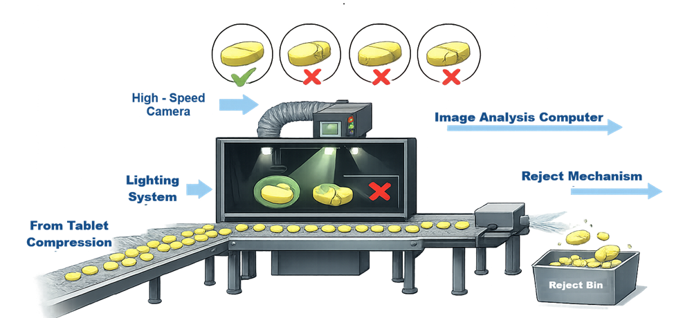
A vision system may inspect:
- Color
- Shape
- Diameter
- Length
- Surface condition
- Chips
- Cracks
- Breakage
- Coating defects
- Embossing
- Score lines
- Capsule cap and body
- Foreign product
- Missing components
- Product orientation
Detection capability depends on the complete imaging arrangement rather than the camera alone.
Product presentation
Reliable inspection may require:
- Consistent product separation
- Controlled orientation
- Product rotation
- Exposure of multiple surfaces
- Stable conveyor position
- Prevention of overlapping units
- Removal of dust
- Prevention of excessive vibration
A defect located on an unexposed surface cannot be detected by a camera that never sees that surface.
Lighting and optics
Vision performance can be affected by:
- Light intensity
- Light color or wavelength
- Lighting angle
- Glare
- Shadows
- Lens focus
- Aperture
- Camera position
- Background color
- Window contamination
- Dust
- Equipment vibration
Lighting should be treated as a controlled inspection component. Replacement with a nominally similar light may affect image quality and require assessment.
Inspection recipes and algorithms
Product recipes may define:
- Product dimensions
- Expected color
- Regions of interest
- Edge detection
- Surface thresholds
- Defect-size limits
- Embossing pattern
- Orientation logic
- Confidence threshold
- Reject decision
- Image retention
Qualification should challenge both acceptable and defective units. Testing only defective units does not evaluate false rejection of acceptable product.
Where machine-learning models are used, uncontrolled automatic learning should not change the approved inspection model during GMP production. Model training, approval, deployment, versioning, and change control should be defined.
False accepts and false rejects
Inspection performance includes two different errors:
- A false accept occurs when a defective unit is classified as acceptable.
- A false reject occurs when an acceptable unit is classified as defective.
Increasing sensitivity may reduce false accepts while increasing false rejects. The operating threshold should be justified according to defect risk and process capability.
A high reject rate should be investigated. It may indicate:
- Actual process deterioration
- Incorrect recipe
- Poor product presentation
- Lighting or sensor drift
- Excessively sensitive thresholds
- Product variation outside the trained or qualified range
- Mechanical instability
- Contamination of optical surfaces
Rejected units should not be repeatedly reinspected until they pass unless a controlled and justified procedure permits it.
Tablet dedusters
Tablet dedusters remove loose powder and small fragments before downstream inspection or metal detection.
The illustration below shows tablets moving through a deduster before inspection.
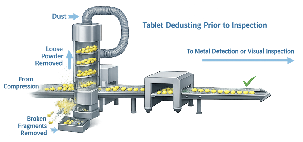
A deduster is primarily material-handling and product-cleaning equipment rather than a defect-classification system. Its operation may nevertheless affect inspection capability.
Important variables may include:
- Vibration
- Product residence time
- Vertical conveying rate
- Dust-extraction airflow
- Product throughput
- Screen or spiral condition
- Tablet attrition
- Broken-tablet removal
- Discharge alignment
Inadequate dedusting can interfere with vision inspection or contaminate downstream equipment. Excessive vibration or aggressive movement may damage tablets.
Manual visual inspection
Manual inspection may be used for:
- Sampled in-process inspection
- Defect investigation
- Product-development studies
- Verification of automated inspection
- Low-volume manufacturing
- Products not suitable for automated inspection
The illustration below shows a manual inspection station with controlled lighting and a defined inspection area.
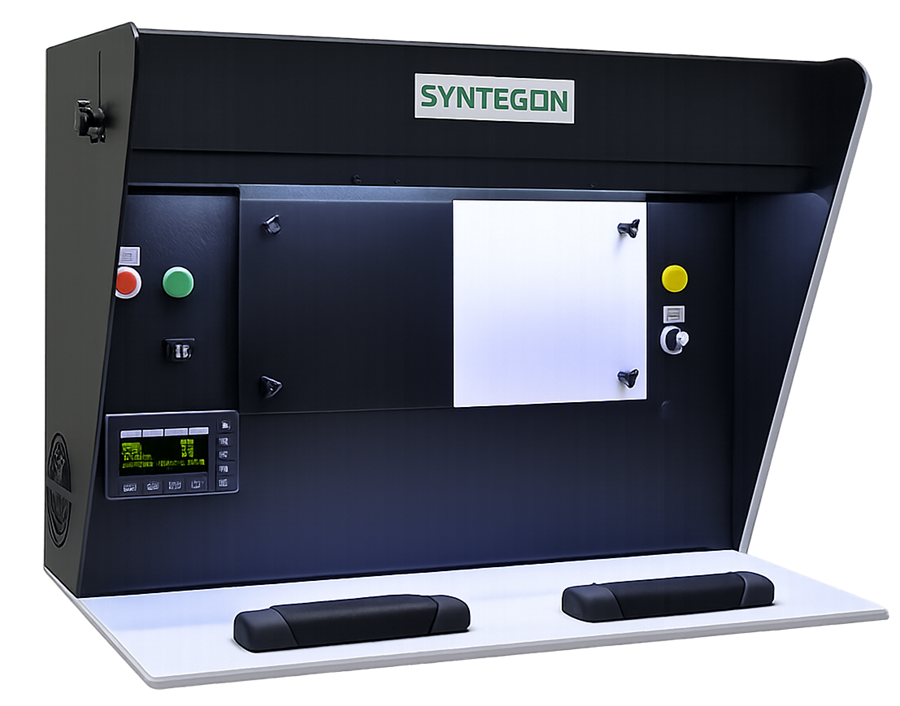
The inspection method should define:
- Defect categories
- Defect standards
- Sample quantity
- Lighting
- Background
- Viewing distance
- Inspection time
- Product manipulation
- Magnification where used
- Inspector qualification
- Rest periods
- Documentation
- Acceptance criteria
Manual inspection capability may be affected by fatigue, inspection speed, visual acuity, training, defect prevalence, and subjective interpretation.
Defect standards
A defect library may include:
- Photographs
- Physical defect samples
- Simulated defects
- Dimensional references
- Written descriptions
- Severity classifications
Physical standards should be identified, protected, periodically reviewed, and replaced when deterioration changes their appearance.
Inspector qualification
Inspector qualification may evaluate:
- Visual acuity
- Color discrimination where relevant
- Understanding of defect categories
- Correct classification
- Detection of known defects
- False-reject performance
- Performance under defined inspection conditions
Qualification should reflect the actual products and defects inspectors are expected to evaluate.
Sampling-based inspection
When inspection is based on sampling rather than examination of every unit, the sampling plan should define:
- Lot or batch
- Sampling location
- Sampling time
- Sample size
- Randomization method
- Defect classifications
- Acceptance criteria
- Escalation or resampling rules
- Batch disposition
- Statistical basis
The illustration below presents a conceptual acceptance-sampling sequence.
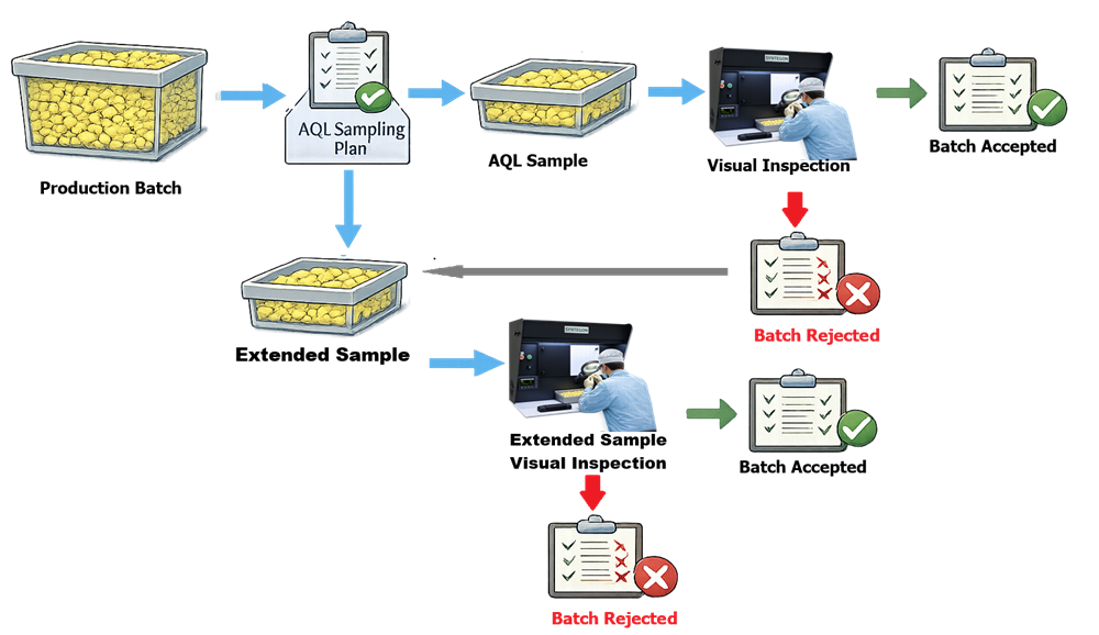
Acceptance quality limit, or AQL, plans may support certain sampled inspection activities. The selected plan should be justified by product risk, defect severity, batch size, process knowledge, and the purpose of inspection.
An AQL plan does not mean that the accepted batch contains no defects. It establishes a statistical decision rule for the sampled lot.
Additional principles are addressed in sampling plan and data collection strategy.
Reject-system architecture
The reject system converts a detection or classification decision into physical removal of the affected unit.
Reject mechanisms may include:
- Pneumatic pusher
- Air blast
- Diverter gate
- Drop flap
- Retractable conveyor
- Vacuum removal
- Rotary diverter
- Machine-station rejection
The illustration below shows a reject mechanism directing identified units into a segregated container.
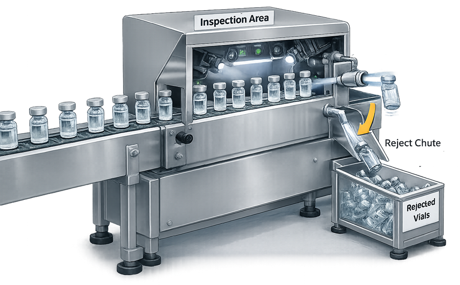
The complete reject sequence may include:
- Defect detection
- Unit tracking
- Delay calculation
- Reject-device actuation
- Unit diversion
- Reject confirmation
- Reject-bin control
- Event recording
- Accepted-product flow confirmation
Tracking and reject timing
The distance between detection and rejection creates a tracking requirement. The system may use:
- Conveyor encoder
- Machine index position
- Time delay
- Product sensor
- Shift register
- Station tracking
Reject timing should remain correct across the approved speed range.
Qualification should challenge:
- Minimum speed
- Maximum speed
- Speed changes
- Irregular product spacing
- Consecutive rejects
- Closely spaced units
- Startup
- Shutdown
- Line interruption
- Product accumulation
Incorrect timing may reject an acceptable unit while allowing the defective unit to continue downstream.
Reject confirmation and segregation
Reject confirmation may use:
- Photoelectric sensor
- Chute sensor
- Bin-entry sensor
- Gate-position switch
- Accepted-stream confirmation
- Reconciliation logic
The system should define its response when rejection cannot be confirmed. Depending on risk, the response may include:
- Alarm
- Line stop
- Product isolation
- Increased inspection
- Investigation
- Reconciliation
- Assessment of potentially affected units
Reject bins should be:
- Present
- Correctly positioned
- Identified
- Secured
- Sized for the expected reject volume
- Protected against unauthorized removal
- Monitored for full condition where required
- Controlled during emptying
Rejected product must not be capable of returning to the accepted stream.
Challenge-test strategy
Challenge testing verifies that defined unacceptable conditions are detected and rejected under representative operating conditions. Challenge sets may include:
- Metal test standards
- Low-, acceptable-, and high-weight units
- Known visual defects
- Missing units
- Incorrect colors
- Damaged tablets or capsules
- Incorrect embossing
- Reject-confirmation failure
- Full or absent reject bin
- Consecutive defects
Challenge samples should be:
- Identified
- Controlled
- Traceable
- Representative
- Protected against accidental release
- Reconciled after testing
- Periodically inspected or verified
Challenge frequency should reflect system risk, operating history, process duration, and the consequences of undetected failure.
A successful challenge at the beginning of a run does not prove that the system remained functional for the entire run. Appropriate end-of-run or periodic checks may be required.
Critical performance characteristics
Detection capability
Detection capability should be defined for specific defects and product conditions. Claims should identify:
- Defect type
- Size
- Contrast
- Location
- Orientation
- Product
- Speed
- Presentation
- Applicable recipe
Measurement performance
Measurement systems may require evaluation of:
- Accuracy
- Repeatability
- Linearity
- Range
- Resolution
- Dynamic response
- Classification around limits
- Environmental influence
Reject effectiveness
Reject effectiveness includes:
- Correct unit rejected
- Defective unit removed
- Accepted unit retained
- Reject confirmation
- Segregation
- Event recording
- Fail-safe response
Throughput
Inspection capability should be verified at the maximum approved production rate and relevant lower rates. Maximum mechanical conveyor speed does not establish maximum qualified inspection speed.
Availability and bypass control
Inspection bypasses should be restricted and controlled. The system should define:
- Authorized use
- Required approval
- Alarm or status indication
- Electronic record
- Product segregation
- Compensating inspection
- Return to normal operation
Automation and computerized-system controls
Automated inspection systems may include:
- Programmable controllers
- Industrial computers
- Vision software
- Product recipes
- Algorithms
- Defect libraries
- Databases
- Operator interfaces
- Network connections
- Historians
- Batch-report functions
- Manufacturing-system interfaces
Controls should address:
- User access
- Recipe approval
- Threshold changes
- Audit trails where applicable
- Software and algorithm versions
- Configuration backup
- Data backup and recovery
- Time synchronization
- Image retention
- Data transfer
- Cybersecurity
- System restart
- Interface failures
Inspection results used for GMP decisions should remain attributable to the applicable product, batch, recipe, date, time, and equipment configuration.
Data interpretation and trending
Inspection systems may generate:
- Inspected-unit count
- Accepted-unit count
- Reject count
- Reject reason
- Defect category
- Weight data
- Metal-detector events
- Alarm history
- Challenge results
- Images
- False-reject investigations
- Bypass events
Reconciliation should account for:
- Accepted units
- Rejected units
- Samples
- Challenge pieces
- Units removed during setup
- Units isolated during faults
- Units transferred downstream
Reject trends may identify deterioration in upstream tablet compression, capsule filling, coating, tooling, materials, or equipment setup.
User requirements and design qualification
The URS should define measurable requirements for:
- Intended products
- Defect types
- Detection limits
- Measurement range
- Product dimensions
- Product orientation
- Throughput range
- Inspection coverage
- False-accept and false-reject objectives
- Reject mechanism
- Reject confirmation
- Reject-bin controls
- Challenge standards
- Electronic records
- Recipe management
- Interfaces
- Cleaning
- Environmental conditions
- Safety functions
- Supplier documentation
Design qualification should confirm that the selected inspection and reject architecture satisfies intended use and controls identified risks.
Supplier documentation, FAT, and SAT
Supplier documentation may include:
- General arrangement drawings
- Conveyor drawings
- Sensor and camera specifications
- Lighting specifications
- Metal-detector specifications
- Checkweigher specifications
- Reject-system drawings
- Functional specifications
- Software and configuration documentation
- Alarm and interlock lists
- Recipe descriptions
- Interface specifications
- Calibration procedures
- Challenge-test procedures
- Maintenance recommendations
- Operating manuals
Factory acceptance testing may verify:
- Product transport
- Sensor operation
- Camera and lighting functions
- Inspection recipes
- Measurement functions
- Reject timing
- Reject confirmation
- Alarms and interlocks
- User access
- Data recording
- Interfaces
Site acceptance testing should verify equipment condition after delivery and operation with installed conveyors, line speeds, products, utilities, controls, and upstream and downstream equipment.
Qualification lifecycle
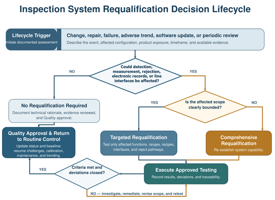
The illustration below summarizes the inspection-system lifecycle from requirements and design review through qualification, routine verification, change control, and requalification.
Installation qualification
Installation qualification should verify, as applicable:
- Equipment identity and location
- Mechanical installation and alignment
- Conveyor and guides
- Sensor, camera, lens, and lighting installation
- Metal-detector aperture
- Weighing conveyor
- Encoder and tracking components
- Reject device
- Reject confirmation
- Reject bin
- Guards and safety devices
- Utilities
- Instruments and calibration status
- Control hardware
- Software and firmware versions
- Network interfaces
- Drawings and manuals
Installation discrepancies should be documented and assessed before release.
Operational qualification
Operational qualification should challenge the system throughout its approved operating ranges.
Testing may include:
- Minimum and maximum speed
- Product-spacing range
- Sensor operation
- Camera and lighting functions
- Recipe selection
- Threshold limits
- Metal test standards
- Checkweigher reference units
- Known vision defects
- Consecutive defects
- Reject timing
- Reject confirmation
- Reject-bin absence or full condition
- Alarm and interlock challenges
- Bypass control
- Power-loss and restart behavior
- User access
- Data recording
- Backup and recovery
- Interface failures
OQ should verify both detection and physical rejection. Demonstrating a correct screen message without verifying removal from the product stream is insufficient.
Equipment-level performance qualification
Equipment-level PQ demonstrates that the installed inspection and reject system performs reproducibly with representative products and line conditions.
Testing may evaluate:
- Representative product sizes and presentations
- Routine and maximum operating speeds
- Product spacing
- Detection performance
- Measurement performance
- False rejects
- Consecutive rejects
- Reject confirmation
- Long-duration operation
- Line stops and restarts
- Upstream and downstream integration
- Data recording
- Reconciliation
Equipment-level PQ does not require multiple commercial batches merely because the stage is called PQ. Scope should be based on equipment risk, intended use, product configurations, and operating conditions.
Product-specific inspection recipes and defect libraries may require separate validation or confirmation when products, colors, shapes, embossing, materials, or defect risks differ.
Manual inspection validation
Manual inspection validation should address the inspection process rather than treating the workstation alone as the complete system. The scope may include:
- Inspection procedure
- Lighting
- Product presentation
- Defect library
- Defect classifications
- Inspector qualification
- Inspection duration
- Breaks and rotation
- Sample size
- Acceptance criteria
- Documentation
- Periodic reassessment
Qualification of the light source or workstation does not establish inspector capability.
Calibration and routine verification
Measuring instruments should be managed under the applicable calibration program and metrology control.
Potentially applicable devices include:
- Checkweigher load cells
- Reference weights
- Conveyor-speed measurement
- Encoders
- Light meters
- Dimensional references
- Pressure instruments
- Timers
- Portable test equipment
Routine functional verification may include:
- Metal test pieces
- Known-weight units
- Vision defect standards
- Reject challenges
- Reject-confirmation challenges
- Alarm checks
Calibration and routine functional challenge testing serve different purposes and should be documented accordingly.
Preventive maintenance
Preventive maintenance may address:
- Conveyor belts
- Bearings
- Guides
- Encoders
- Sensors
- Cameras
- Lenses
- Lighting
- Optical windows
- Metal-detector aperture
- Weighing conveyor
- Load cell
- Reject actuator
- Air supply
- Reject sensors
- Guards
- Industrial computers
- Cooling fans
Maintenance frequency should reflect criticality, use, failure history, environmental conditions, supplier recommendations, and observed drift.
Broader principles are addressed in preventive maintenance and equipment reliability.
Common failure modes
| Failure mode | Potential effect | Typical control |
|---|---|---|
| Dirty camera window | Reduced defect visibility | Inspection and cleaning |
| Lighting deterioration | Image variation or missed defects | Light monitoring and verification |
| Incorrect vision recipe | Wrong thresholds or defect criteria | Recipe control and product verification |
| Product overlap | Incomplete inspection | Spacing control and overlap detection |
| Checkweigher drift | Incorrect classification | Calibration and dynamic verification |
| Excessive vibration | Unstable weight or image | Mechanical isolation and maintenance |
| Metal-detector interference | False signals or reduced sensitivity | Installation assessment and challenge testing |
| Incorrect reject delay | Wrong unit rejected | Encoder and timing challenges |
| Reject actuator failure | Defective unit remains accepted | Reject confirmation and fail-safe response |
| Full or missing reject bin | Loss of reject segregation | Bin sensors and line interlock |
| Bypass used without control | Uninspected product passes downstream | Restricted access and documented segregation |
| Uncontrolled algorithm change | Altered detection performance | Version and change control |
| Data-interface failure | Missing or incorrect records | Interface alarm and reconciliation |
| Deteriorated defect standard | Invalid challenge | Standard inspection and replacement |
Change control and requalification
Changes should be assessed for effects on inspection capability, rejection, records, and validated product recipes.
Examples include:
- New product
- New size, shape, color, or embossing
- New defect type
- Threshold change
- Camera or lens replacement
- Lighting replacement
- Sensor relocation
- Conveyor-speed increase
- Reject-device change
- Encoder replacement
- Metal-detector setting change
- Checkweigher load-cell replacement
- Software or algorithm update
- Defect-library revision
- Network or interface change
- Equipment relocation
The impact assessment should determine whether the change requires:
- Document revision
- Calibration
- Functional verification
- Targeted IQ or OQ
- Product-recipe validation
- Equipment-level PQ
- Inspector requalification
- Data-integrity assessment
- Requalification
Periodic review and continued verification
Periodic review should evaluate:
- Qualification status
- Product recipes
- Defect libraries
- Challenge results
- Calibration
- Maintenance
- Reject rates
- False rejects
- Detection failures
- Alarm history
- Bypass events
- Deviations
- Software versions
- User access
- Backup and recovery
- Supplier support
- Obsolescence
- Changes
- Requalification decisions
Adverse trends should be evaluated for both inspection-system deterioration and upstream process deterioration.
Documentation and traceability
Lifecycle documentation should connect:
- Intended use
- User requirements
- Defect classifications
- Design specifications
- Risk assessments
- Supplier documentation
- FAT and SAT
- IQ, OQ, and equipment-level PQ
- Challenge standards
- Product recipes
- Inspection algorithms
- Calibration
- Routine verification
- Maintenance
- Training
- Reject reconciliation
- Electronic records
- Deviations
- Change controls
- Periodic reviews
- Requalification decisions
The documentation should demonstrate that the defined defect was detected, the correct unit was rejected, rejection was confirmed, and the event was recorded.
Regulatory basis
21 CFR 211.63 requires equipment to be appropriately designed, adequately sized, and suitably located for intended use, cleaning, and maintenance.
21 CFR 211.68 addresses automatic, mechanical, electronic, and computerized equipment, including calibration, inspection, checks, and controls over computerized records.
21 CFR 211.110 requires appropriate in-process controls and tests to monitor manufacturing output and sources of variability.
FDA’s Process Validation: General Principles and Practices places equipment qualification within the manufacturing-process lifecycle and emphasizes continued monitoring of process performance.
Conclusion
Solid dosage inspection systems must reliably present the product, detect or measure defined conditions, apply approved decision logic, track the affected unit, reject it, confirm rejection, maintain segregation, and create accurate records.
Qualification should challenge the complete detection-and-rejection chain under representative products, speeds, positions, and fault conditions. Routine verification, maintenance, recipe control, data review, change control, periodic review, and requalification must maintain that capability throughout the equipment lifecycle.
Inspection remains a control layer. It does not replace capable upstream manufacturing processes, representative sampling, analytical testing, investigation, or final product disposition.