

Pharmaceutical Granulation Equipment: Design, Process Control, and Qualification
Granulation equipment converts powders into larger, more manageable agglomerates or compacted ribbons. The operation can improve flow, reduce segregation, control particle-size distribution, and support consistent downstream milling, blending, tablet compression, or capsule filling.
Equipment design and control can strongly influence granule density, porosity, moisture, strength, and size distribution. Qualification must therefore demonstrate that the equipment is properly designed, installed, and capable of operating within its approved ranges.
Equipment qualification does not, by itself, validate a product-specific granulation process. Formulation development, establishment of process parameters, process performance qualification, and continued process verification remain part of the manufacturing-process validation lifecycle.
Purpose and scope
This article addresses the design, functionality, process controls, qualification, and lifecycle management of pharmaceutical granulation equipment, including:
- High-shear wet granulators
- Fluid-bed granulators
- Roller compactors used for dry granulation
- Continuous and twin-screw granulation systems
- Binder preparation and delivery systems
- Integrated wet mills, transfer equipment, controls, and supporting utilities
- Equipment-level DQ, IQ, OQ, and PQ
- Calibration, maintenance, cleaning, change control, and requalification
The article does not establish formulation-specific granulation endpoints, product acceptance criteria, commercial batch validation requirements, or continued process verification strategies. Those subjects belong to product and process development and manufacturing-process validation.
Granulation within solid dosage manufacturing
Granulation commonly follows material dispensing and premixing. Depending on the method, it may be followed by drying, milling, final blending, compression, or capsule filling.
A typical sequence may include:
- Dispensing and material handling
- Blending or premixing
- Granulation
- Drying when wet granulation is used
- Milling or sizing
- Final blending
- Tablet compression or capsule filling
The illustration below shows how granulation integrates with upstream material preparation and downstream solid-dosage operations.
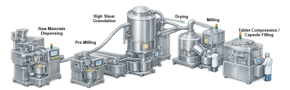
The exact sequence depends on the formulation, granulation method, facility layout, and equipment configuration. Integrated systems may combine several operations within one contained processing train.
Principal granulation methods
Wet granulation
Wet granulation uses a liquid binder or granulating fluid to promote particle adhesion. Liquid may be added to a mechanically mixed powder bed or sprayed onto fluidized particles.
Important equipment functions include:
- Uniform powder movement
- Controlled binder addition
- Consistent liquid distribution
- Management of mechanical and thermal energy
- Repeatable endpoint detection
- Controlled discharge and wet sizing
- Prevention of uncontrolled material buildup
Wet granules generally require a subsequent drying step unless granulation and drying are performed within an integrated fluid-bed system.
Dry granulation
Dry granulation forms larger particles without adding a liquid binder. Roller compaction is the most common pharmaceutical dry-granulation method.
Powder is fed between counter-rotating rolls and compacted into ribbons or flakes. The compacted material is then milled into granules of the required size range.
Dry granulation may be appropriate for materials that are sensitive to moisture or elevated drying temperatures. However, compaction conditions can affect ribbon density, granule strength, fines generation, and downstream compressibility.
Continuous granulation
Continuous systems feed material and, when applicable, granulating liquid into a continuously operating processing chamber. Twin-screw granulators use rotating screw elements to convey, mix, wet, and agglomerate the material.
Important design considerations include:
- Feed-rate accuracy
- Liquid-to-solid ratio
- Screw configuration
- Screw speed
- Residence-time distribution
- Startup and shutdown material
- Material diversion
- Traceability between input material and collected output
- Integration with downstream drying or milling
Qualification must address both steady-state operation and defined transient conditions.
High-shear granulators
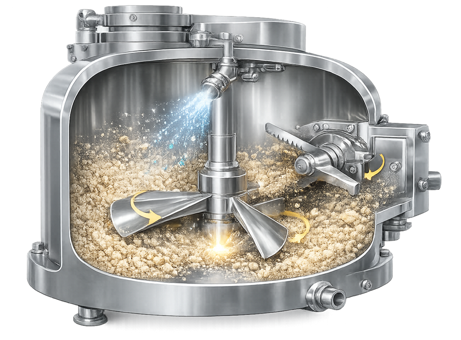
A high-shear granulator normally includes a mixing bowl, main impeller, chopper, binder-addition system, drive assemblies, discharge mechanism, instrumentation, and control system.
The impeller circulates and densifies the powder bed. The chopper helps break wet masses and distribute the binder, although its actual contribution depends on formulation and equipment geometry.
The illustration below shows a representative high-shear granulator and its principal processing components.
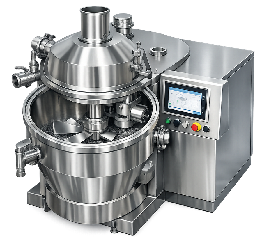
Equipment capacity should be defined by demonstrated minimum and maximum working loads rather than vessel volume alone. Material movement can change substantially with batch size, fill level, powder properties, and impeller geometry.
Potentially important operating variables include:
- Powder charge and fill level
- Dry-mixing time
- Impeller speed
- Chopper speed
- Binder concentration and temperature
- Binder addition rate
- Total liquid addition
- Wet-massing time
- Product temperature
- Impeller torque or motor power
- Discharge time and wet-mill settings
Torque or power may provide useful information about changes in wet-mass consistency. It should not be treated as a universal endpoint unless its relationship to the intended material attributes has been established.
Fluid-bed granulators
A fluid-bed granulator suspends particles in conditioned process air while binder solution is sprayed into the moving bed. The equipment may perform granulation and drying in the same vessel, but the configured capabilities and approved operating sequence must be defined for the specific system.
The illustration below shows the airflow, product chamber, spray system, filtration arrangement, and exhaust path of a typical fluid-bed granulator.
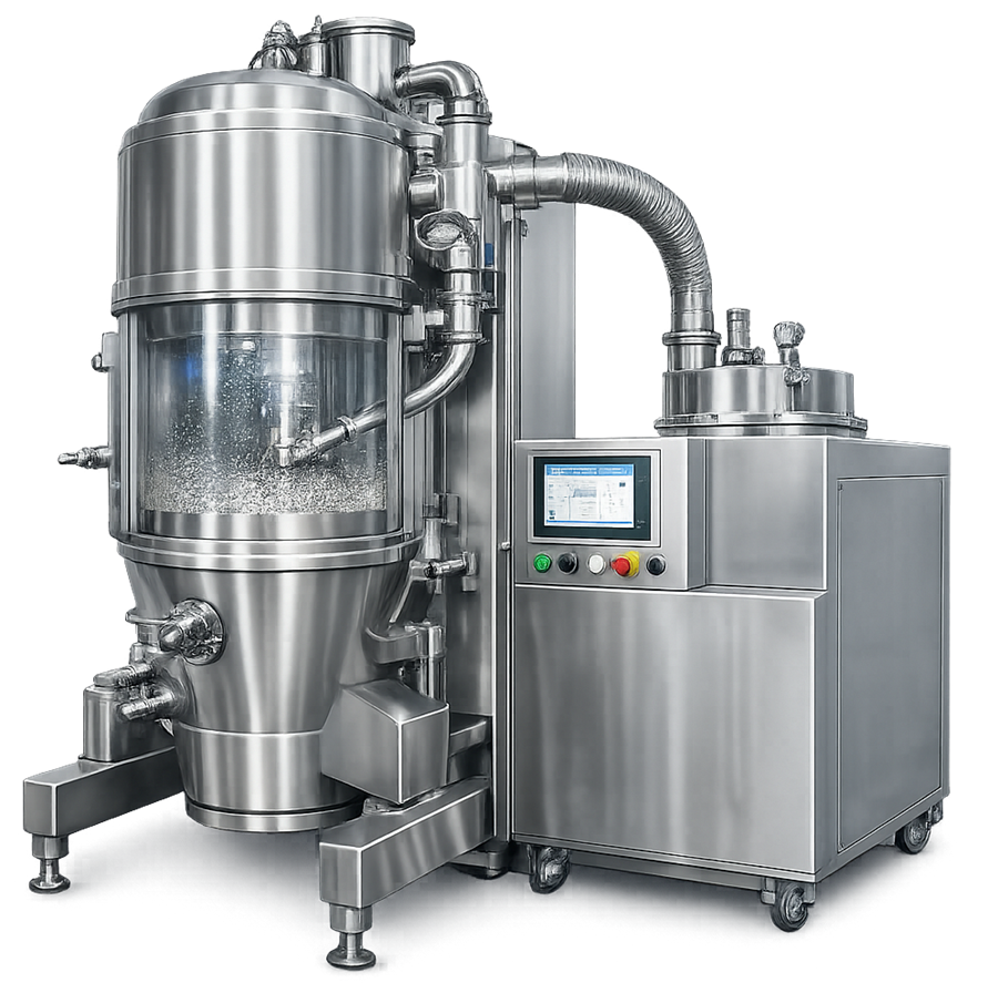
Potentially important parameters include:
- Inlet-air temperature
- Inlet-air volume or velocity
- Inlet-air humidity
- Product and exhaust-air temperature
- Spray rate
- Atomization pressure
- Spray pattern and droplet size
- Nozzle position
- Filter differential pressure
- Product load
- Fluidization behavior
- Granulation time
- Drying time and moisture endpoint
Poor fluidization can create nonuniform wetting, localized overwetting, agglomerate buildup, or incomplete drying. Excessive airflow may cause attrition, fines generation, or increased filter loading.
Product filters, filter-shaking mechanisms, air-distribution plates, spray nozzles, and exhaust controls are therefore critical parts of the functional design.
Roller compactors
A roller compactor normally includes a powder feeder, deaeration or tamping arrangement, feed screws, compaction rolls, side seals, roll-gap control, force measurement, ribbon discharge, and an integrated or downstream mill.
The illustration below shows the principal material path through a pharmaceutical roller compactor and dry-granulation system.
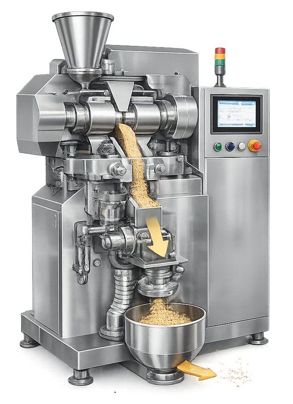
Potentially important variables include:
- Powder feed rate
- Feed-screw and tamping-screw speed
- Roll speed
- Roll force or hydraulic pressure
- Roll gap
- Side-seal condition
- Ribbon thickness
- Ribbon density
- Ribbon temperature
- Milling speed
- Screen type and aperture
- Recycle or fines-handling strategy
The control approach may maintain roll gap, roll force, or a defined relationship between them. Qualification should challenge the actual control mode used by the equipment.
Variability in powder feeding or entrained air can cause ribbon-density changes even when displayed roll force remains stable. Feed-system performance must therefore be evaluated together with the compaction rolls.
Granulator design and critical components
Mixing vessel and processing geometry
Vessel shape, working volume, impeller position, blade profile, wall clearance, and chopper location determine how material moves through a high-shear granulator.
The illustration below identifies the primary mechanical elements that establish powder circulation and wet-mass distribution.
Design review should evaluate:
- Minimum and maximum operating loads
- Potential dead zones
- Wall and lid buildup
- Impeller and chopper clearances
- Shaft-seal design
- Discharge completeness
- Access for inspection and cleaning
- Repeatable assembly after maintenance
Scale-up should not be based on vessel volume alone. Tip speed, power per unit mass, liquid distribution, fill level, and mixing geometry may change differently as equipment size increases.
Binder preparation and delivery
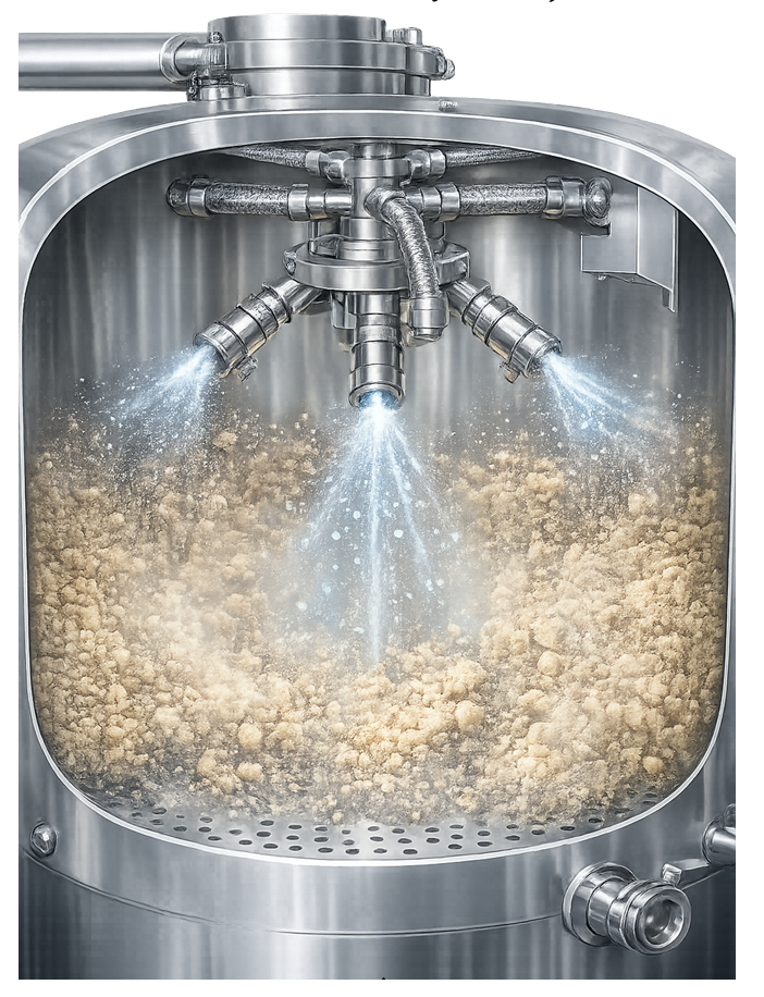
A binder-delivery system may include a preparation vessel, agitator, transfer pump, tubing, flowmeter, pressure indication, control valve, spray manifold, and one or more nozzles.
The illustration below shows the functional arrangement of a binder spray nozzle used to distribute granulating liquid into a fluidized or mechanically mixed powder bed.
The system should provide:
- Controlled and measurable liquid delivery
- Stable spray pressure
- Suitable atomization
- Reproducible spray pattern
- Prevention or detection of nozzle blockage
- Drainability and cleaning access
- Identification of replaceable nozzle components
- Verification of correct assembly and orientation
A total binder quantity alone does not demonstrate consistent delivery. The addition rate, spray pattern, droplet formation, and interaction with the moving powder bed may be equally important.
Drives and mechanical energy
Impeller, chopper, screw, and roll drives must operate across their specified speed, torque, and load ranges. Drive sizing should consider startup under loaded conditions and foreseeable high-resistance conditions.
Where torque or motor power is used for monitoring or endpoint decisions, the measurement chain should be included within calibration or verified through an appropriate documented control.
Material feed and discharge
Material feed systems may include gravity chutes, vacuum transfer, loss-in-weight feeders, screw feeders, or contained charging devices. Their design should minimize segregation, bridging, uncontrolled feed variation, and dust release.
Discharge systems should provide reproducible emptying without excessive retention or mechanical damage. Integrated wet mills or dry-granulation mills should be addressed as separate functional subsystems with defined screens, speeds, interlocks, and assembly checks.
Product-contact materials and surface finish
Product-contact materials must be compatible with the product, binder, cleaning agents, and expected operating conditions. Surface finish should be specified according to intended use, cleanability, material-adhesion risk, and the site’s hygienic-design requirements.
A single surface-roughness value is not universally necessary for every component. The specification should be justified for the particular service.
Product-contact seals, gaskets, lubricants, filters, hoses, and polymers should be identified and supported by appropriate material documentation.
Containment and dust control
Powder charging, dry mixing, discharge, roller compaction, milling, filter cleaning, and equipment opening may release airborne material.
Containment provisions may include:
- Closed material transfer
- Local extraction
- Split butterfly valves
- Isolators or glovebox interfaces
- Negative-pressure enclosures
- High-containment filter arrangements
- Safe-change filter housings
- Wash-in-place systems
The required containment level must be established through product and occupational-risk assessments. Broader facility controls are addressed in containment and dust collection systems.
Process control strategy
The control strategy should connect material attributes, equipment parameters, alarms, procedural controls, and measurements to the intended granulation outcome.
| Granulation method | Equipment parameters commonly controlled | Material or process responses commonly monitored |
|---|---|---|
| High-shear wet granulation | Impeller speed, chopper speed, binder rate, liquid quantity, mixing time | Torque, power, product temperature, visual behavior, granule attributes |
| Fluid-bed granulation | Airflow, inlet temperature, humidity, spray rate, atomization pressure | Product temperature, exhaust temperature, filter differential pressure, moisture or PAT response |
| Roller compaction | Feed rate, screw speed, roll speed, roll force, roll gap | Ribbon thickness, density, fines, granule-size distribution |
| Continuous granulation | Powder feed, liquid feed, screw speed, barrel condition | Residence behavior, torque, temperature, moisture, material diversion status |
The illustration below summarizes how material attributes and controlled equipment parameters influence granulation responses and downstream performance.
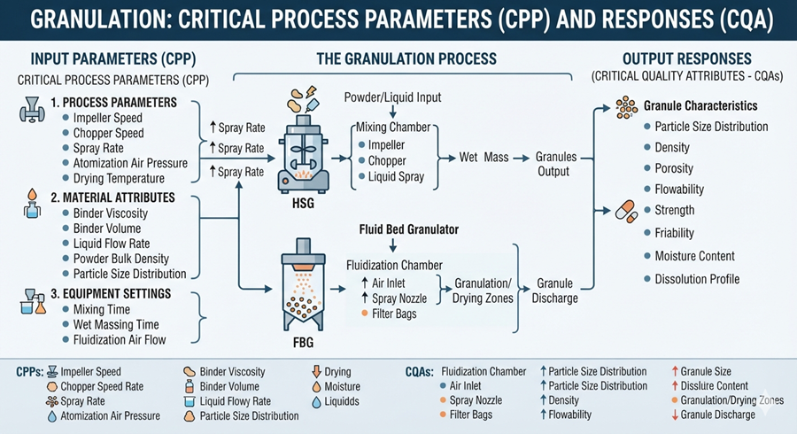
Parameter ranges used during routine manufacturing must be justified through process development and process validation. Equipment qualification demonstrates that the system can accurately and repeatably achieve the ranges assigned to it.
Instrumentation and automation
Granulation equipment may use instruments for:
- Speed
- Torque and power
- Weight
- Temperature
- Airflow
- Humidity
- Differential pressure
- Liquid flow
- Spray pressure
- Roll force
- Roll gap
- Product moisture or other PAT measurements
The automation boundary may include programmable controllers, operator interfaces, recipe management, data historians, electronic batch-record interfaces, variable-frequency drives, instrument transmitters, and safety controllers.
Automation controls should address, as applicable:
- User access
- Recipe creation and approval
- Parameter limits
- Alarm management
- Interlocks
- Manual and automatic modes
- Data acquisition
- Audit trails
- Time synchronization
- Backup and recovery
- Interfaces with external systems
- Controlled software and configuration changes
Safety controls and GMP process controls may use shared hardware, but their requirements and verification should remain traceable.
Cleaning and changeover
Granulation equipment can present difficult cleaning locations, including:
- Impeller and chopper seals
- Binder tubing and nozzles
- Product filters
- Air-distribution plates
- Feed screws
- Roll surfaces and side seals
- Discharge valves
- Integrated mills
- Transfer connections
- Internal ledges and concealed cavities
Cleaning design should support safe access, defined disassembly, visual inspection, drainage, drying, and repeatable reassembly. Automated washing cycles should control relevant time, temperature, flow, pressure, detergent concentration, and sequence parameters.
Equipment qualification can verify that cleaning functions operate as designed. It does not replace the product-residue, cleaning-agent, microbial, sampling, recovery, and acceptance evidence required by the site’s cleaning validation approach.
User requirements and design qualification
The user requirements specification should define intended use and measurable requirements for:
- Granulation method
- Products and material characteristics
- Batch-size range or continuous throughput
- Processing capacity
- Required operating ranges
- Binder-delivery capability
- Product-contact materials
- Containment
- Cleaning method
- Utilities
- Instrumentation
- Automation and electronic records
- Sampling
- Discharge and transfer
- Facility integration
- Maintenance access
- Documentation and training
Design qualification should confirm that the proposed design satisfies these requirements and that identified risks are adequately controlled.
Design review should include the granulator and all required supporting systems rather than treating the main vessel as the complete equipment boundary.
Supplier documentation, FAT, and SAT
Supplier documentation may include:
- General arrangement drawings
- Process and instrumentation diagrams
- Electrical drawings
- Instrument lists
- Materials certificates
- Surface-finish documentation
- Component data sheets
- Software and functional specifications
- Alarm and interlock lists
- Recommended maintenance
- Spare-parts information
- Operating and cleaning manuals
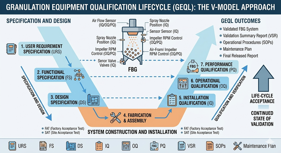
Factory acceptance testing can verify fabrication, controls, recipes, alarms, sequences, and mechanical operation before shipment. Site acceptance testing confirms condition after delivery and verifies installed operation with site utilities and interfaces.
FAT results may support qualification when tests are approved, traceable, properly documented, and unaffected by shipment or installation. FAT does not automatically replace site verification.
The illustration below presents the V-model validation lifecycle from requirements and design review through qualification, routine operation, change control, and requalification.
Installation qualification
Installation qualification should verify, as applicable:
- Equipment identity and location
- Approved drawings and specifications
- Product-contact components
- Materials and certificates
- Impellers, choppers, screws, rolls, screens, and nozzles
- Drive assemblies and guards
- Utilities and environmental interfaces
- Instrument installation
- Calibration status
- Electrical and automation installation
- Lubricants and potential product-contact risks
- Filters and airflow components
- Drainage and cleaning connections
- Safety and containment features
- Software and firmware versions
- Required manuals and maintenance instructions
Deviations from the approved design must be documented, assessed, and resolved or formally accepted.
Operational qualification
Operational qualification should challenge the equipment throughout its approved operating ranges and verify its functional controls. Testing may include:
- Minimum and maximum speeds
- Timers and sequence controls
- Binder pump and spray-rate ranges
- Flow, pressure, and temperature controls
- Airflow and filter differential-pressure controls
- Roll-force and roll-gap controls
- Feed-rate controls
- Loaded or simulated-load operation
- Alarm and interlock challenges
- Power-loss and restart behavior
- Emergency stopping
- Recipe limits
- Manual and automatic modes
- Data recording
- Discharge and transfer functions
- Cleaning sequences
Operating-range challenges should be selected from documented risks and intended use. Testing every possible parameter combination is neither necessary nor normally practical.
Equipment-level performance qualification
Equipment-level PQ demonstrates that the installed system can perform its intended equipment functions reproducibly under representative operating conditions.
Depending on the equipment, testing may use suitable placebo, surrogate, development material, or qualified product batches. The rationale should consider mechanical loading, powder behavior, binder delivery, containment, cleanability, and the risks being challenged.
Equipment-level PQ may evaluate:
- Operation at representative minimum and maximum loads
- Reproducibility of mixing and binder delivery
- Stable fluidization
- Feed and discharge performance
- Roller-compaction control
- Integrated mill operation
- Repeatable execution of equipment recipes
- Equipment cleaning and changeover functions
- Material recovery
- Containment performance
- Performance after extended operation
Equipment-level PQ should not claim that a commercial formulation is validated or that the granulation process consistently produces acceptable finished product. Those conclusions require product-specific process knowledge and process performance qualification.
The distinction between qualification and PPQ is further addressed in performance qualification and general principles of process validation.
Common failure modes and controls
| Failure mode | Potential consequence | Typical detection or control |
|---|---|---|
| Binder nozzle blockage | Nonuniform wetting or undersized granules | Flow or pressure monitoring, spray inspection, cleaning |
| Poor atomization | Local overwetting or broad size distribution | Atomization-pressure control and nozzle verification |
| Impeller or chopper malfunction | Inadequate mixing or large wet masses | Speed feedback, motor-load monitoring, alarm |
| Torque or power drift | Misleading endpoint indication | Calibration or verification, trend review |
| Loss of fluidization | Uneven wetting or drying | Airflow, pressure, temperature, and filter monitoring |
| High filter differential pressure | Reduced airflow or process instability | Differential-pressure alarm and filter management |
| Feeder bridging | Variable roller-compactor throughput | Hopper design, agitation, feed-rate monitoring |
| Roll-gap or force drift | Variable ribbon density | Closed-loop control, calibration, trending |
| Side-seal leakage | Fines generation and variable ribbons | Inspection, setup verification, maintenance |
| Incorrect screen or nozzle | Incorrect granule or spray characteristics | Component identification and line clearance |
| Wrong recipe or parameter set | Operation outside approved conditions | Access control, recipe approval, independent verification |
| Product buildup | Yield loss, cross-contamination, mechanical load | Inspection, cleaning, maintenance, recovery monitoring |
Calibration and maintenance
Instruments used to control, monitor, or make acceptance decisions should be included in the applicable calibration and maintenance control.
The program should define:
- Instrument range and required accuracy
- Calibration or verification interval
- Acceptance tolerances
- Traceability
- Handling of out-of-tolerance results
- Assessment of affected production data
- Post-maintenance checks
Preventive maintenance should address wear items such as seals, bearings, belts, filters, nozzles, feed screws, rolls, side seals, screens, drive components, and discharge mechanisms.
Maintenance frequency should be adjusted using equipment criticality, supplier information, failure history, condition monitoring, and operating experience. Broader reliability principles are discussed in preventive maintenance and reliability.
Change control and requalification
Changes should be evaluated for their potential effect on qualified equipment functions and validated manufacturing processes. Examples include:
- Impeller, chopper, screw, roll, or screen changes
- New nozzle type or spray location
- Modified operating ranges
- Control-software or recipe changes
- Instrument replacement
- Binder-system modification
- New batch-size range
- Utility or air-handling change
- Cleaning-cycle modification
- Containment modification
- Major repair or relocation
- New material with substantially different processing characteristics
Requalification scope should be based on the impact assessment. A change may require document updates, targeted testing, partial requalification, full requalification, process-development work, or additional process validation.
Periodic review should consider deviations, alarms, calibration history, maintenance, cleaning performance, changes, recurring failures, operating trends, and continued suitability for intended use.
Documentation and traceability
Lifecycle documentation should provide traceability among:
- User requirements
- Design specifications
- Risk assessments
- Supplier documentation
- FAT and SAT
- Qualification protocols and reports
- Instruments and calibration records
- Software and configuration records
- Operating and cleaning procedures
- Training
- Deviations
- Maintenance
- Change controls
- Requalification decisions
- Process-development and validation documents
The documentation should clearly distinguish equipment capability from product-specific process acceptance.
Regulatory basis
21 CFR Part 211, Subpart D establishes requirements concerning equipment design, construction, cleaning, maintenance, calibration, inspection, and controls over automatic, mechanical, and electronic equipment.
FDA’s Process Validation: General Principles and Practices separates facility and equipment qualification from process performance qualification and continued process verification.
Where process analytical technology is used, FDA’s PAT guidance provides a framework for using process understanding and timely measurements to support manufacturing control.
Conclusion
Pharmaceutical granulation equipment must provide controlled material movement, energy input, binder delivery, airflow, compaction, discharge, and data capture appropriate to its intended use.
A sound lifecycle begins with defined user requirements and design review, continues through supplier assessment, FAT, SAT, DQ, IQ, OQ, and equipment-level PQ, and remains supported by calibration, maintenance, cleaning, change control, periodic review, and justified requalification.
Qualification demonstrates that the equipment is capable of performing its assigned functions. Product-specific development, PPQ, and continued verification establish whether the complete manufacturing process consistently produces material meeting its predetermined quality requirements.