

Solid Dosage Blending Equipment: Design, Uniformity, and Qualification
Solid dosage blending equipment distributes active pharmaceutical ingredients, excipients, lubricants, glidants, colors, and other formulation components throughout a powder mixture. The equipment must provide controlled particle movement while limiting segregation, material loss, contamination, and unintended changes to powder properties.
Blender qualification demonstrates that the equipment is designed correctly, installed as specified, and capable of operating reproducibly throughout its approved ranges. It does not establish that every formulation processed in the blender will achieve acceptable blend uniformity or finished-dosage-unit content uniformity.
Product-specific blending studies, sampling strategies, process performance qualification, and continued process verification must establish and maintain the validated manufacturing process.
Purpose and scope
This article addresses:
- Tumbling and mechanically agitated blending equipment
- Blender selection and system boundaries
- Mixing mechanisms
- Material and equipment factors affecting uniformity
- Loading, blending, discharge, and transfer controls
- Blend-uniformity sampling and analytical considerations
- Process analytical technology
- Containment and cleaning interfaces
- Automation and electronic records
- URS, DQ, supplier documentation, FAT, SAT, IQ, OQ, and equipment-level PQ
- Calibration, maintenance, change control, periodic review, and requalification
The article does not establish product-specific mixing times, formulation-development strategy, universal blend-uniformity acceptance criteria, PPQ batch requirements, or finished-product content-uniformity criteria.
Blending within solid dosage manufacturing
Blending may occur at several points in a solid dosage manufacturing process. A formulation may require premixing before granulation, blending after drying and milling, lubricant blending immediately before compression, or separate blending stages for low-concentration ingredients.
The illustration below shows one representative solid dosage manufacturing sequence. The actual order of operations must be defined for the specific product and process.

Upstream and downstream equipment may include:
- Dispensing and material handling systems
- Pharmaceutical milling equipment
- Pharmaceutical granulation equipment
- Pharmaceutical drying equipment
- Tablet compression equipment
- Capsule filling equipment
Blending does not necessarily eliminate segregation created during discharge, transfer, vibration, or downstream feeding. The equipment boundary and process-control strategy must therefore extend beyond the rotating vessel when connected handling operations can affect blend composition.
Blending equipment types
V-blenders
A V-blender consists of two connected cylindrical sections mounted in a V-shaped configuration. Vessel rotation repeatedly divides, combines, and redistributes the powder bed.
The illustration below shows a representative pharmaceutical V-blender and its principal mechanical arrangement.
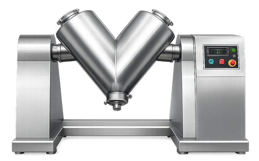
V-blenders are generally suited to dry powders that can move freely under tumbling conditions. Their relatively gentle action can limit particle damage, but cohesive materials or components with substantially different particle properties may require additional controls.
An intensifier bar may be installed to break soft agglomerates or assist distribution of low-concentration ingredients. Its use introduces additional shear, heat, seals, cleaning surfaces, and operating parameters that must be included within the equipment assessment.
Double-cone blenders
A double-cone blender uses two conical sections joined at their bases. Rotation causes the powder bed to tumble between the two ends and redistribute through the center of the vessel.
The illustration below shows a pharmaceutical double-cone blender used for gentle powder blending.
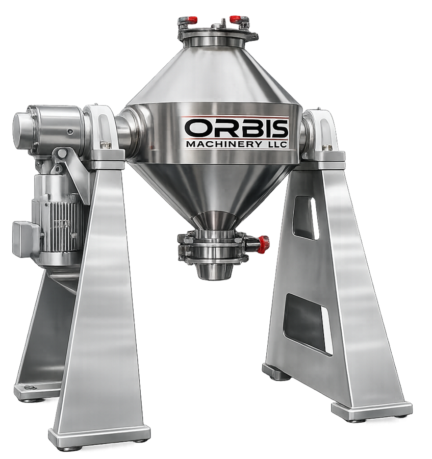
The symmetrical geometry can support controlled powder movement and discharge. Performance still depends on fill level, rotational speed, loading sequence, material properties, vessel geometry, and discharge behavior.
Potential retained-product locations include the discharge valve, internal seams, ports, baffles, intensifier-bar assemblies, and gasket interfaces.
Bin and intermediate bulk container blenders
A bin blender rotates a removable container within a powered lifting and blending frame. The same container may be used for charging, blending, staging, transport, and discharge.
The illustration below shows a removable pharmaceutical bin installed in a blending frame.
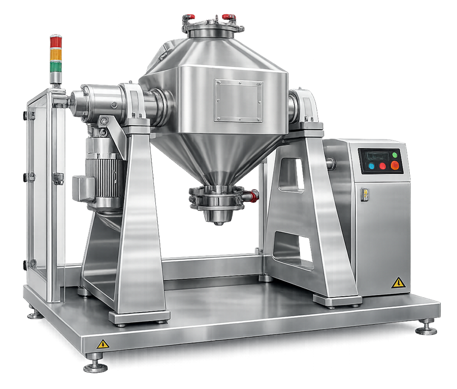
Bin blending can reduce open transfers and intermediate equipment handling. The qualified configuration includes more than the drive frame. It may include:
- Approved bin types and sizes
- Container-retention devices
- Lift and rotation mechanisms
- Bin identification
- Lid and discharge valves
- Docking components
- Grounding provisions
- Position sensors
- Safety interlocks
- Downstream discharge interfaces
Bins that differ in geometry, internal volume, discharge cone, surface condition, or baffle arrangement should not automatically be treated as interchangeable.
Ribbon mixers
A ribbon mixer uses one or more helical ribbons mounted on a horizontal shaft. Rotation produces axial and radial movement through the powder bed. The illustration below shows a pharmaceutical ribbon mixer with an internal helical agitator.
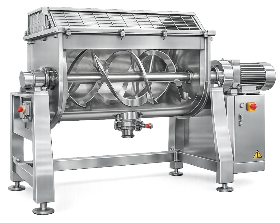
Ribbon mixers provide more active convective movement than conventional tumbling blenders. Their suitability depends on the formulation and intended use because the agitator may generate greater shear, heat, attrition, or compaction.
Important design areas include:
- Ribbon geometry and shaft clearances
- End seals and bearings
- Trough geometry
- Working-volume range
- Drive capacity
- Discharge-valve configuration
- Prevention of product retention beneath the shaft or at vessel ends
- Access for inspection and cleaning
High-shear mixers
High-shear mixers use an impeller and, where installed, a chopper to generate intensive convective and shear movement. The illustration below shows a representative pharmaceutical high-shear mixer.
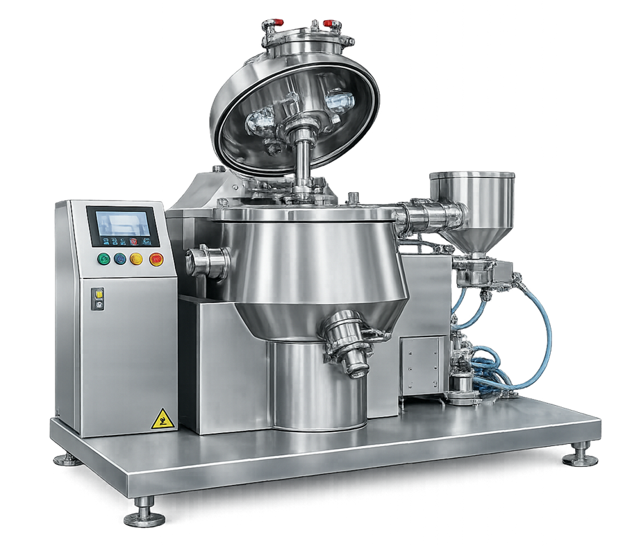
These systems are commonly associated with wet granulation rather than routine final dry blending. When used only to distribute dry ingredients, the intended function and limits must be clearly defined.
High-shear operation can break agglomerates but may also change particle size, density, temperature, electrostatic behavior, or lubricant distribution. Equipment selection should reflect the required material outcome rather than treating stronger mixing as inherently better.
Wet-granulation applications are addressed separately in pharmaceutical granulation equipment.
Planetary mixers
Planetary mixers use blades that rotate around their own axes while also moving around the vessel. They are generally used for cohesive, viscous, wet, or semi-solid materials rather than conventional free-flowing dry blends.
The illustration below shows a representative pharmaceutical planetary mixer.
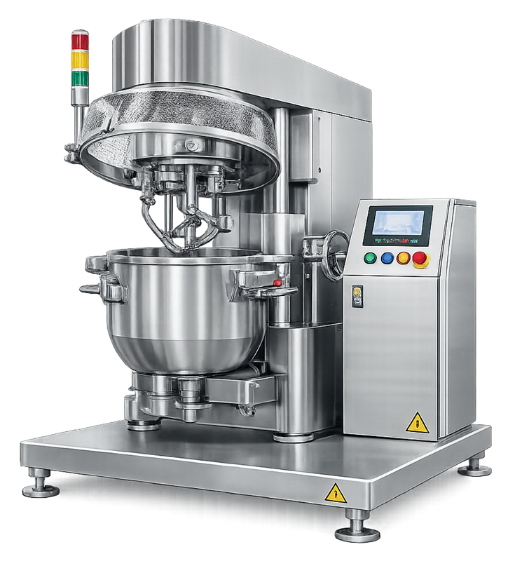
Where a planetary mixer is included within a solid dosage process, its equipment requirements may include:
- Blade geometry and clearance
- Blade and planetary speeds
- Mixing direction
- Bowl position and retention
- Scraper operation
- Drive torque
- Vacuum capability
- Jacket temperature
- Product discharge
- Cleaning and blade reassembly
Its qualification approach should reflect the actual material and process function.
Mixing mechanisms
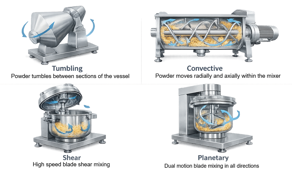
Powder redistribution normally results from multiple mechanisms acting together. Blender descriptions should not imply that one mechanism acts independently throughout the entire batch.
The illustration below compares the principal equipment motions and particle-movement patterns encountered in pharmaceutical mixing systems.
Tumbling and diffusive redistribution
Tumbling occurs when vessel rotation causes the powder bed to lift, roll, divide, and recombine. Individual particles change position as the bed moves, producing gradual diffusive redistribution.
This mechanism is common in V-blenders, double-cone blenders, and rotating bins.
Effective movement depends on:
- Vessel geometry
- Rotation speed
- Fill level
- Powder flow
- Particle friction
- Cohesion
- Internal baffles
- Electrostatic behavior
Convective movement
Convective mixing transfers groups of particles from one region to another. It may result from vessel rotation, ribbons, paddles, impellers, or other internal agitators.
Convective movement can accelerate distribution but does not guarantee uniformity when ingredients differ substantially in concentration, particle size, density, shape, or surface characteristics.
Shear and agglomerate dispersion
Shear occurs when adjacent regions of the powder bed move at different velocities. Controlled shear can break soft agglomerates and distribute cohesive ingredients.
Excessive shear may produce fines, alter particle structure, increase temperature, or overwork lubricants. The required level of shear must therefore be based on the formulation and intended material attributes.
System boundaries and interfaces
The blender boundary should be established before qualification planning. Depending on the system, it may include:
- Fixed or removable blending vessel
- Drive motor and gearbox
- Shaft, bearings, and seals
- Intensifier bar, ribbon, paddle, or impeller
- Lifting and positioning system
- Charging ports
- Vacuum-transfer receiver
- Filters and vent connections
- Spray or liquid-addition system
- Discharge valve
- Bin docking assembly
- Load cells
- Speed and position sensors
- Local control panel
- Programmable controller and operator interface
- Recipe and data-management functions
- Dust-extraction connection
- Grounding and bonding
- Safety guards and interlocks
- Cleaning equipment and wash connections
- Interfaces with upstream and downstream equipment
The qualification boundary and cleaning boundary may differ. A non-product-contact lifting frame may require mechanical qualification but may not belong within the product-contact cleaning boundary.
Material attributes affecting blending
Blender performance is influenced by the materials being processed. Relevant attributes may include:
- Particle-size distribution
- Particle shape
- Bulk and tapped density
- Cohesiveness
- Flowability
- Moisture content
- Electrostatic tendency
- Surface texture
- Friability
- Concentration of each component
- Agglomeration tendency
- Sensitivity to shear or overmixing
Large differences among formulation components can promote segregation during both blending and subsequent handling. Common segregation mechanisms include:
- Sifting of smaller particles through larger particles
- Percolation through void spaces
- Trajectory differences during free fall
- Fluidization of lighter particles
- Dust entrainment
- Vibration during transport or staging
- Preferential retention in equipment
- Segregation during hopper or bin discharge
Equipment qualification can demonstrate repeatable mechanical operation and transfer. Product-specific studies must determine whether the formulation remains acceptably uniform through discharge and downstream processing.
Critical design considerations
Working volume and fill level
Blender size should be selected using the qualified working-volume range rather than gross vessel capacity.
Excessive fill may restrict powder movement. Very low fill may prevent the intended bed movement or place the material outside the effective mixing zone. The acceptable range depends on blender geometry, material properties, and mixing mechanism.
The URS should define the required minimum and maximum batch loads or working volumes. Supplier recommendations can support the initial range but do not replace verification for intended use.
Vessel geometry and internal components
Vessel shape affects powder-bed movement, division, recombination, and discharge. Design review should assess:
- Aspect ratio
- Cone and wall angles
- Internal transitions
- Baffles
- Welds and surface transitions
- Agitator clearances
- Dead zones
- Discharge geometry
- Sampling ports
- Spray ports
- Cleanability
Internal components must be positively identified and assembled consistently. Changes in blade, ribbon, baffle, screen, or intensifier-bar configuration can alter mixing performance.
Materials and surface condition
Product-contact surfaces must be compatible with ingredients, cleaning agents, and expected operating conditions. They should not be reactive, additive, or absorptive in a manner that adversely affects the product.
Surface-finish requirements should be justified by:
- Material adhesion
- Cleaning method
- Product potency
- Corrosion risk
- Visual-inspection capability
- Required hygienic condition
One surface-roughness limit is not universally appropriate for every blender or product-contact component.
Charging and discharge design
Charging and discharge may influence blend uniformity as strongly as the mixing cycle. Design should address:
- Ingredient loading sequence
- Charging location
- Drop height
- Dust generation
- Material retention
- Closed-transfer connections
- Discharge-valve geometry
- Discharge rate
- Downstream container position
- Prevention of uncontrolled vibration
- Complete emptying
- Line clearance
- Cleaning access
A uniform blend inside the vessel may segregate during gravity discharge or transfer. Evaluation should therefore include the complete material path when that path can influence product quality.
Operating parameters and process controls
Loading sequence
The order and method used to charge ingredients can influence initial distribution and the time required to achieve uniformity. Controls may address:
- Material identity
- Quantity
- Addition sequence
- Premixing or geometric dilution
- Screening requirements
- Charging location
- Layering of materials
- Addition of low-concentration ingredients
- Addition of lubricant or glidant
- Prevention of material loss
Loading sequence is generally product-specific and should be established during process development.
Fill level
Fill level should remain within the approved equipment range. It may be controlled by:
- Batch weight
- Material volume
- Load-cell indication
- Approved bin size
- Defined product bulk-density range
- Procedural verification
A fixed batch weight may produce different fill levels when raw-material density changes.
Rotation or agitator speed
Speed influences powder-bed movement and mechanical energy. Excessive speed in a tumbling blender may hold material against the vessel wall and reduce the intended cascading action. Insufficient speed may produce inadequate movement.
The relationship between displayed speed and actual vessel or agitator speed should be verified.
For simple tumbling cycles, total revolutions may be calculated as:
Total revolutions = blender speed × blending time
This calculation can help compare cycles, but equal total revolutions do not prove equivalent blending when speed, scale, fill level, material properties, or equipment geometry differ.
Blending time
Insufficient time may leave concentration gradients or agglomerates. Excessive time does not always improve uniformity and may promote segregation, particle attrition, electrostatic charging, or excessive lubricant distribution.
The approved mixing time or range should come from product and process knowledge. Equipment qualification confirms accurate cycle timing and repeatable execution of the assigned setpoint.
Intensifier-bar or agitator operation
Where an intensifier bar, ribbon, paddle, or impeller is used, the control strategy should define:
- Speed
- Direction
- Operating duration
- Sequence relative to vessel rotation
- Permitted load
- Interlocks
- Expected motor load
- Cleaning and assembly status
Lubricant blending
Lubricants such as magnesium stearate may require controlled addition and limited mixing. Excessive lubricant distribution can influence tablet hardness, dissolution, compactability, and downstream equipment performance.
Lubricant-blending conditions are product-specific. They should not be established solely through generic blender qualification.
Hold time and discharge
The process should define the allowable conditions between blending and downstream use. Relevant factors include:
- Maximum hold time
- Container closure
- Environmental exposure
- Vibration
- Number of transfers
- Transport distance
- Discharge sequence
- Downstream feeding behavior
Blend hold-time and transport studies belong to process validation when they are needed to demonstrate continued product uniformity.
Blend uniformity and sampling
Blend uniformity describes the distribution of formulation components within the powder mixture. It is related to, but not identical to, finished-dosage-unit content uniformity.
A blend may appear uniform based on limited samples while segregation occurs during discharge or tablet-press feeding. Conversely, an intrusive sampling device may produce biased samples that do not accurately represent the surrounding powder bed.
Sampling strategy
A blend-uniformity sampling strategy should define:
- Study objective
- Sampling method
- Sampling locations
- Number of samples
- Sample size
- Sampling depth
- Sampling sequence
- Equipment state
- Sampling device
- Replicate handling
- Discharge sampling
- Analytical method
- Statistical evaluation
- Predetermined acceptance criteria
The illustration below identifies six representative locations within a V-blender. These locations are conceptual and must not be treated as a universal sampling plan.
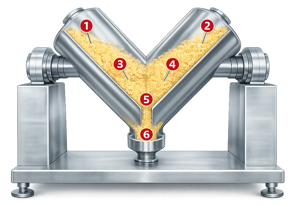
Potential sampling locations may include:
- Upper regions of each blender chamber
- Mid-depth regions
- Vessel junction
- Areas near walls or internal components
- Region near the discharge valve
- Early, middle, and late discharge fractions
Locations should be selected from equipment geometry, powder movement, loading method, segregation risk, and the intended study objective.
Additional sampling principles are addressed in sampling plan and data collection strategy.
Sampling-device limitations
A powder thief can disturb the powder bed, collect different particle sizes unevenly, compress the sample, or allow material from several depths to enter the sampling cavity.
The sampling method should be demonstrated to produce representative results for the material and study purpose. Increasing the number of samples does not correct a systematically biased sampling method.
Sample size
Sample size should be appropriate for the question being evaluated. A large sample may average local concentration differences and conceal nonuniformity. An excessively small sample may introduce high analytical and sampling variability.
Blend sample size and dosage-unit size serve different purposes and should not automatically be made equal without scientific justification.
Data evaluation
Blend-uniformity results may be evaluated using:
- Individual sample results
- Mean concentration
- Range
- Standard deviation
- Relative standard deviation
- Location-related patterns
- Discharge-fraction patterns
- Trends with blending time
- Comparison among batches
- Assessment of analytical and sampling variability
No single relative-standard-deviation limit is universally suitable for every formulation, concentration, method, sampling design, or development stage. Acceptance criteria should be scientifically justified and established before study execution.
Determining blending time
Time-point studies may be used during process development to identify when the mixture reaches an acceptable state and whether additional mixing creates improvement, no meaningful change, or adverse effects.
The study should evaluate more than the earliest acceptable time point. The proposed operating range should account for routine variation in materials, load, equipment operation, sampling, and analysis.
Equipment OQ verifies timer accuracy and cycle execution. Product-specific blending-time studies establish the process parameter.
Process analytical technology
Near-infrared spectroscopy or another suitable process analytical technology may be used to monitor changes in blend composition without repeatedly opening the equipment.
A PAT application may require control of:
- Measurement location
- Probe orientation
- Optical window condition
- Sampling frequency
- Spectral preprocessing
- Calibration model
- Reference method
- Model range
- Data exclusions
- Endpoint algorithm
- Software version
- Model maintenance
- Data storage and review
A stable spectral response is not automatically equivalent to acceptable blend uniformity. The endpoint method must be connected to the intended material attribute and supported by appropriate development and validation evidence.
Material transfer and process integration
Blending systems may be integrated with vacuum receivers, intermediate containers, bin lifters, docking valves, downstream hoppers, tablet presses, capsule fillers, or other processing equipment.
The illustration below shows a representative V-blender connected to controlled charging and discharge equipment.
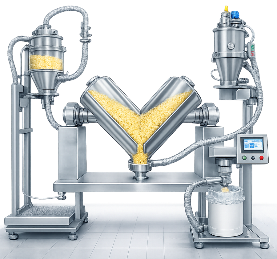
Integrated testing should verify:
- Correct equipment sequencing
- Container identification
- Docking and alignment
- Transfer permissives
- Valve operation
- Dust-extraction coordination
- Blender start prevention when improperly positioned
- Discharge control
- Communication between control systems
- Safe response to interruption or power loss
- Material recovery
- Prevention of unintended cross-transfer
A transfer test demonstrating that powder moves successfully does not establish that the material remains uniform. Product-specific validation must assess segregation when the transfer can affect blend composition.
Containment and dust control
Blender charging, sampling, discharge, cleaning, and filter handling may release pharmaceutical powder.
Controls may include:
- Closed transfer
- Contained docking valves
- Sealed bins
- Vacuum transfer
- Local exhaust
- Isolators
- Disposable liners
- Vent filters
- Negative-pressure enclosures
- Safe-change arrangements
- Wash-in-place systems
Containment requirements should be established from material hazard, batch quantity, dustiness, task duration, room design, and occupational-exposure objectives.
The associated pharmaceutical powder containment and dust collection systems article addresses dust-extraction architecture, filtration, airflow, monitoring, and qualification.
Hygienic design and cleaning
Blender design should support effective cleaning, inspection, drying, and controlled reassembly.
Locations requiring particular attention may include:
- Discharge valves
- Shaft seals
- Intensifier-bar penetrations
- Baffles
- Ribbon and paddle supports
- Gasket interfaces
- Sampling ports
- Spray nozzles
- Vent filters
- Bin lids
- Docking valves
- Internal corners
- Welds and surface transitions
Cleaning may be manual, clean-out-of-place, wash-in-place, or a combination. Qualification can verify equipment access, sequence operation, spray-device function, flow, pressure, temperature, drainage, and drying.
These activities do not replace the residue limits, sampling recovery, analytical-method capability, worst-case selection, and reproducibility required by the site’s cleaning validation approach.
Automation and computerized-system boundaries
Automated blender functions may include:
- Container identification
- Lift and docking control
- Speed control
- Direction control
- Cycle timing
- Recipe management
- Ingredient or batch verification
- Load-cell input
- Interlocks
- Alarm management
- Electronic records
- Data transfer to manufacturing systems
The computerized-system boundary should identify controllers, operator interfaces, drives, sensors, network connections, servers, recipe databases, electronic records, and external interfaces.
Controls should address:
- Authorized access
- Approved recipes
- Setpoint limits
- Manual-mode restrictions
- Audit trails where applicable
- Data accuracy
- Time synchronization
- Backup and recovery
- Configuration control
- Software changes
- System security
User requirements and design qualification
The URS should define measurable requirements for:
- Intended products and materials
- Blender type
- Batch-size and working-volume range
- Bin or vessel configurations
- Required speeds and cycle durations
- Direction of rotation
- Agitators or intensifier bars
- Charging and discharge
- Containment
- Cleaning
- Materials of construction
- Surface condition
- Sampling provisions
- Instruments
- Automation
- Electronic records
- Facility interfaces
- Maintenance access
- Documentation
- Safety functions
Design qualification should confirm that the proposed design satisfies intended use and adequately controls identified risks.
The review should assess the complete installed configuration rather than only the blending vessel.
Supplier documentation, FAT, and SAT
Supplier documentation may include:
- General arrangement drawings
- Product-contact drawings
- Materials certificates
- Surface-finish documentation
- Drive and gearbox information
- Rated load and working-volume data
- Electrical drawings
- Instrument lists
- Functional specifications
- Software and configuration documentation
- Alarm and interlock lists
- Cleaning instructions
- Maintenance recommendations
- Spare-parts lists
- Operating manuals
Factory acceptance testing may verify fabrication, rotation, speed control, lifting, positioning, alarms, interlocks, recipes, operator controls, and safety functions before shipment.
Site acceptance testing should verify equipment condition after delivery and operation with installed utilities, containers, controls, and facility interfaces.
Approved and traceable FAT results may support qualification. They should be repeated at the site when installation, transport, configuration, utilities, or site interfaces could affect the result.
Installation qualification
Installation qualification should verify, as applicable:
- Equipment manufacturer, model, and identification
- Installed location and orientation
- Approved vessel or bin configurations
- Product-contact materials
- Surface documentation
- Drive, gearbox, and support structure
- Agitators and intensifier bars
- Discharge valve
- Guards and safety devices
- Lifting and retention mechanisms
- Utilities
- Grounding and bonding
- Dust-extraction connections
- Instruments and calibration status
- Control hardware
- Software and firmware versions
- Drawings and manuals
- Lubricants
- Recommended spare parts
- Cleaning and maintenance requirements
Discrepancies from the approved design should be documented and assessed before release.
Operational qualification
Operational qualification should demonstrate correct operation throughout the approved equipment range.
Testing may include:
- Minimum and maximum speed
- Direction of rotation
- Cycle-timer accuracy
- Start, stop, pause, and restart functions
- Emergency stops
- Guards and access interlocks
- Bin retention
- Lift travel and position sensors
- Agitator or intensifier-bar operation
- Discharge-valve control
- Load-cell function
- Recipe and parameter limits
- Alarm challenges
- Manual and automatic modes
- Power-loss response
- Data recording
- Control-system interfaces
- Operation under representative mechanical load
OQ establishes equipment capability. It does not determine the validated mixing time for a specific pharmaceutical formulation.
Equipment-level performance qualification
Equipment-level PQ should demonstrate that the installed blender can execute its intended equipment functions reproducibly under representative operating conditions.
Testing may evaluate:
- Representative minimum and maximum loads
- Repeatability of vessel rotation or agitation
- Loaded start and stop
- Bin lifting and positioning
- Charging and discharge
- Material recovery
- Retained material
- Integrated transfer
- Containment
- Cleaning functionality
- Repeated recipe execution
- Extended operation where relevant
Suitable surrogate materials may be used when they challenge the mechanical and handling characteristics relevant to the equipment.
A tracer-distribution study may provide useful equipment-development information, but it does not establish that every formulation will blend uniformly. Its limitations should be documented, particularly when tracer concentration, particle properties, loading method, and segregation tendency differ from commercial products.
Equipment qualification versus process validation
The distinction must remain explicit:
| Equipment qualification | Product-specific process validation |
|---|---|
| Confirms installation and configuration | Confirms the approved formulation and manufacturing process |
| Verifies speed, timing, direction, lifting, interlocks, and alarms | Establishes loading sequence, blending time, and operating ranges |
| Challenges equipment operating ranges | Evaluates formulation and raw-material variability |
| Demonstrates mechanical loading and discharge capability | Demonstrates blend and dosage-unit uniformity |
| Evaluates equipment repeatability | Evaluates batch-to-batch process reproducibility |
| Verifies data and automation functions | Establishes PPQ and continued-verification requirements |
| Does not validate a commercial formulation | Supports the conclusion that the manufacturing process remains in control |
Product-specific validation is addressed in PPQ strategy and batch definition and general principles of process validation.
Calibration and maintenance
Instruments used to control, record, or make GMP decisions should be managed under the applicable calibration program and metrology control.
Relevant devices may include:
- Speed indicators
- Cycle timers
- Load cells
- Position sensors
- Torque or motor-load indicators
- Temperature sensors
- Pressure or vacuum instruments
- PAT instruments
- Portable reference instruments used during qualification
Preventive maintenance should address:
- Drive motors
- Gearboxes
- Bearings
- Shaft seals
- Agitators
- Intensifier bars
- Lift mechanisms
- Brakes
- Container-retention devices
- Discharge valves
- Gaskets
- Filters
- Grounding connections
- Guards
- Position switches
Maintenance frequency should reflect equipment criticality, use, supplier recommendations, failure history, and condition. Broader principles are addressed in preventive maintenance and equipment reliability.
Common failure modes and controls
| Failure mode | Potential effect | Typical control |
|---|---|---|
| Incorrect blender or bin selected | Unapproved geometry or capacity | Equipment identification and recipe control |
| Incorrect ingredient sequence | Delayed or incomplete distribution | Approved batch instructions and verification |
| Underfilling or overfilling | Inadequate powder movement | Batch-weight or volume limits |
| Incorrect speed or cycle time | Inadequate mixing or segregation | Recipe limits and recorded feedback |
| Agitator or intensifier-bar failure | Agglomerates or incomplete distribution | Speed feedback, motor monitoring, alarm |
| Excessive blending | Segregation, attrition, or over-lubrication | Validated time range and recipe control |
| Discharge-valve retention | Yield loss or carryover | Hygienic design, inspection, cleaning |
| Bin not secured | Mechanical or safety failure | Retention interlocks and position verification |
| Sampling bias | Misleading uniformity conclusion | Qualified sampling method and study design |
| Segregation during discharge | Nonuniform downstream feed | Discharge studies and controlled transfer |
| Wrong recipe | Operation outside approved parameters | Access control and recipe approval |
| Uncontrolled software change | Loss of validated configuration | Change control and configuration management |
| Worn seal or bearing | Contamination or abnormal operation | Inspection and preventive maintenance |
| Incomplete cleaning | Cross-contamination | Cleaning procedure and cleaning validation |
Change control and requalification
Changes should be evaluated for their effect on equipment qualification and product-specific process validation.
Potentially significant changes include:
- Different vessel or bin geometry
- New batch-size range
- Modified speed range
- New agitator, baffle, or intensifier bar
- Discharge-valve replacement
- Control-software change
- Recipe modification
- Instrument replacement
- New loading or discharge system
- Transfer-route change
- Containment modification
- Cleaning-process change
- Major repair
- Equipment relocation
- New formulation with substantially different powder behavior
The impact assessment should determine whether the change requires:
- Document revision
- Calibration or functional verification
- Targeted IQ or OQ
- Equipment-level PQ
- Cleaning assessment
- Product-development work
- Additional blend-uniformity studies
- PPQ or other process-validation activity
Requalification should be based on the affected functions and risks rather than automatically repeating every original test.
Periodic review and continued verification
Periodic equipment review should evaluate:
- Qualification status
- Changes
- Deviations
- Alarms
- Calibration history
- Maintenance history
- Recurring failures
- Cleaning performance
- Software and recipe status
- Bin and component inventory
- Instrument obsolescence
- Supplier support
- Requalification decisions
Product continued verification should separately evaluate relevant process and quality data, including blend results, tablet or capsule results, deviations, material variability, and downstream performance.
Documentation and traceability
Lifecycle documentation should connect:
- Intended use
- User requirements
- Design specifications
- Risk assessments
- Supplier documentation
- FAT and SAT
- IQ, OQ, and equipment-level PQ
- Instruments and calibration
- Automation configuration
- Operating recipes
- Cleaning procedures
- Maintenance
- Training
- Deviations
- Change controls
- Periodic reviews
- Requalification
- Product-development studies
- PPQ and continued-verification records
The records should permit a reviewer to distinguish equipment capability from product-specific evidence of blend and dosage-unit uniformity.
Regulatory basis
21 CFR 211.63 requires manufacturing equipment to be appropriately designed, adequately sized, and suitably located for its intended use, cleaning, and maintenance.
21 CFR 211.67 establishes requirements for equipment cleaning, maintenance, written procedures, and records.
21 CFR 211.68 addresses automatic, mechanical, electronic, and computerized equipment, including routine calibration, inspection, checks, and controls over computerized records.
21 CFR 211.110 requires appropriate in-process controls and specifically identifies adequacy of mixing to assure uniformity and homogeneity.
FDA’s Process Validation: General Principles and Practices places equipment qualification within Stage 2 process qualification while treating PPQ and continued process verification as separate lifecycle activities.
Conclusion
Solid dosage blending depends on the interaction of equipment geometry, material properties, fill level, loading sequence, speed, mixing time, discharge, transfer, sampling, and downstream handling.
Equipment qualification must demonstrate that the blender and its supporting systems are properly installed and can execute their assigned functions throughout approved operating ranges. It must not be used as a substitute for formulation-specific process development, blend-uniformity evaluation, PPQ, or continued process verification.
The qualified state is maintained through calibration, maintenance, cleaning controls, controlled recipes, change assessment, periodic review, and risk-based requalification.