

Pharmaceutical Lyophilizer Design & Components
Purpose and Scope
A pharmaceutical lyophilizer removes water from a frozen product by sublimation during primary drying and desorption during secondary drying. The equipment integrates a vacuum-rated chamber, temperature-controlled shelves, vapor condenser, refrigeration system, vacuum system, instrumentation, automated controls, and—in many aseptic applications—cleaning, sterilization, sterile-gas, loading, unloading, and stoppering functions.
The lyophilizer design must support the intended:
- Product types and formulations
- Container-closure systems
- Batch and loading configurations
- Shelf-temperature range and ramp rates
- Chamber-pressure range and control accuracy
- Maximum ice load and peak sublimation rate
- Cleaning and sterilization strategy
- Aseptic-processing boundary
- Loading, unloading, and stoppering approach
- Electronic batch records and data-integrity requirements
This article addresses equipment architecture and critical components. Verification of installed equipment capability is addressed in lyophilizer system qualification. Product-specific cycle performance is addressed separately in lyophilization process qualification.
Intended Use and System Boundaries
The intended use should be defined before equipment selection and design approval. A development-scale freeze-dryer, production lyophilizer for aseptically filled vials, bulk-product tray dryer, and highly automated pass-through lyophilizer have materially different design requirements.
The system boundary should identify which components are included within the lyophilizer and which are qualified or controlled separately. Depending on the installation, the boundary may include:
- Product chamber and doors
- Shelf stack and stoppering mechanism
- Condenser and vapor duct
- Refrigeration packages
- Heat-transfer-fluid circulation system
- Vacuum pumps and pressure-control components
- Sterile vent and backfill-gas assemblies
- CIP and SIP components
- Hydraulic or mechanical systems
- Loading and unloading equipment
- Local PLC, HMI, historian, and recipe management
- Connections to facility utilities and automation networks
- Interfaces with isolators, RABS, filling lines, and capping equipment
The equipment boundary should not be confused with the process-validation boundary. Equipment qualification demonstrates lyophilizer capability. Process validation establishes that a defined formulation, container-closure system, load pattern, and cycle consistently produce acceptable product.
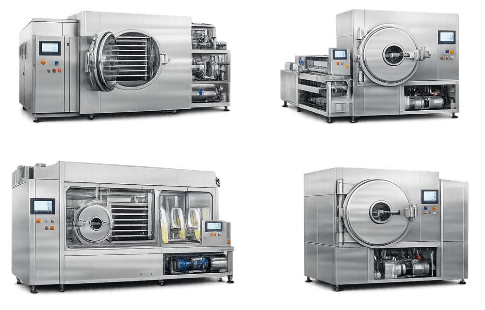
Modern production lyophilizers commonly use modular stainless-steel construction with the chamber, control cabinet, refrigeration package, and vacuum equipment integrated into a coordinated system.
Overall System Architecture
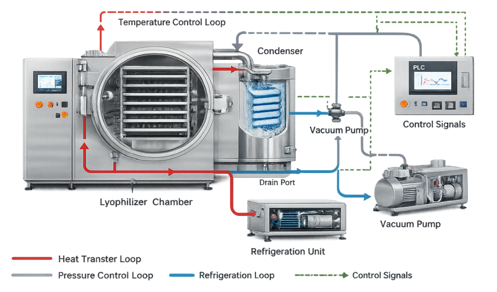
A pharmaceutical lyophilizer normally includes five interdependent functional systems:
- Product chamber and shelves
- Condenser and vapor-flow path
- Shelf and condenser refrigeration
- Vacuum generation and pressure control
- Automation, instrumentation, and data recording
During primary drying, controlled heat supplied through the shelves supports sublimation of ice within the product. Water vapor travels from the chamber through the vapor path and deposits as ice on the condenser surfaces. The condenser captures most of the water vapor, while the vacuum system principally removes noncondensable gases and establishes the required low-pressure environment.
The architecture may use:
- An external condenser connected through a vapor duct
- A condenser located beneath or within the chamber assembly
- One or more refrigeration circuits
- Single or redundant vacuum pumps
- Manual, semiautomatic, or fully automatic loading
- Manual or hydraulic shelf stoppering
- One-door or pass-through chamber configurations
Subsystem sizing must be coordinated. A powerful vacuum pump cannot compensate for inadequate condenser capacity, restricted vapor flow, poor shelf-temperature control, or excessive chamber leakage.
Product Chamber and Door Assembly
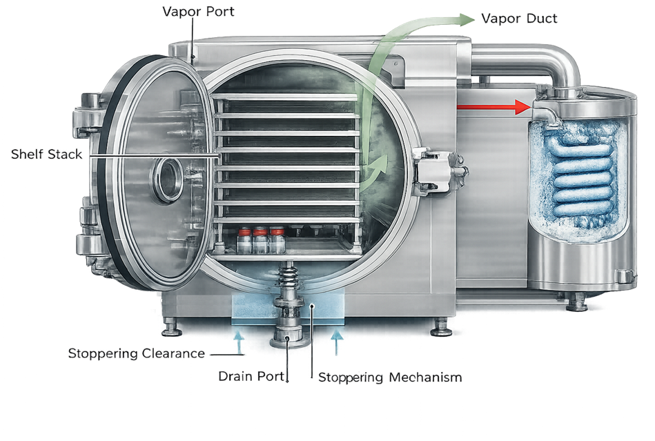
The product chamber is a pressure vessel designed to withstand full vacuum and any positive pressure associated with sterilization, pressure testing, or controlled gas backfill.
Construction and Surface Design
Production chambers are commonly fabricated from corrosion-resistant stainless steel. Material selection should consider:
- Product and cleaning-agent compatibility
- Clean-steam exposure
- Thermal cycling
- Surface-finishing requirements
- Weld quality
- Corrosion resistance
- Long-term mechanical stability
Product-contact and sterile-boundary surfaces should be smooth, accessible, and compatible with the approved cleaning and sterilization strategy. Surface-finish requirements should be defined in the URS rather than assumed from generic industry practice.
Internal geometry should minimize:
- Crevices and difficult-to-clean joints
- Trapped cleaning solution or condensate
- Unnecessary dead legs
- Obstructions to vapor flow
- Areas that cannot be visually inspected or sampled where inspection is required
Chamber Door and Seal
Door design may include:
- Hinged or sliding construction
- Manual or powered actuation
- Inflatable, static, or mechanically compressed seals
- Single-door or pass-through configuration
- Interlocks preventing opening under unsafe pressure conditions
- Position indication and closed-door confirmation
The door gasket must tolerate repeated vacuum, temperature, cleaning, and sterilization cycles. Gasket leakage, deformation, incorrect inflation pressure, or damaged sealing surfaces can cause failed leak-rate tests and unstable chamber pressure.
Pass-through systems require coordinated interlocks so that doors serving different room classifications cannot be opened in an uncontrolled sequence.
Drainability
Chamber and condenser drains should support complete removal of:
- Cleaning solutions
- Sterilization condensate
- Defrost water
- Rinse water
- Residual process liquids introduced during testing
Drain location, chamber slope, valve orientation, condensate routing, and low-point design should be evaluated during design review.
Shelf Assembly and Product Heat Transfer
Shelves support the product containers and establish the controlled thermal conditions used for freezing, primary drying, and secondary drying.
Internal shelf channels circulate a heat-transfer fluid—commonly silicone-based fluid or another suitable thermal medium—through the shelf stack. The thermal system heats or cools this fluid according to the programmed cycle.
Heat-Transfer Mechanisms
Heat transfer to a vial can include:
- Contact conduction between the shelf and vial base
- Gas conduction within the chamber
- Radiation from chamber walls, doors, and adjacent surfaces
- Heat transfer through neighboring containers
The shelf system provides the principal controlled thermal input, but vial position and local surroundings can affect actual product temperature. Edge and corner vials may receive different radiative heat loads than center vials.
Critical Shelf Characteristics
Important design attributes include:
- Shelf flatness
- Shelf spacing
- Thermal-fluid channel configuration
- Fluid-flow distribution
- Shelf-to-shelf temperature consistency
- Edge-to-center temperature uniformity
- Heating and cooling ramp capability
- Maximum and minimum shelf temperatures
- Mechanical strength under full loading
- Vertical alignment
- Surface cleanability
- Compatibility with stoppering compression
Shelf deformation or poor flatness can affect vial contact, product-temperature distribution, and stopper seating. Thermal-fluid maldistribution can produce repeatable hot or cold regions that recipe adjustment alone cannot correct.
Thermal Control Unit
The shelf thermal system may include:
- Heat-transfer-fluid pump
- Heater
- Heat exchanger
- Refrigeration interface
- Expansion tank
- Flow, pressure, and temperature instruments
- Control and bypass valves
- Relief and containment provisions
- Leak detection where justified
The design should prevent leakage of thermal fluid into the product chamber. Maintenance access and detection of internal shelf leakage should be considered during design review.
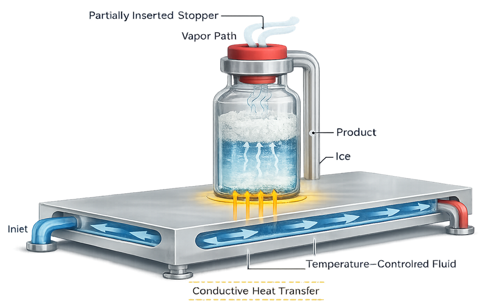
Temperature-controlled shelves provide the principal controlled thermal input during freezing and drying.
Condenser and Vapor-Flow Path
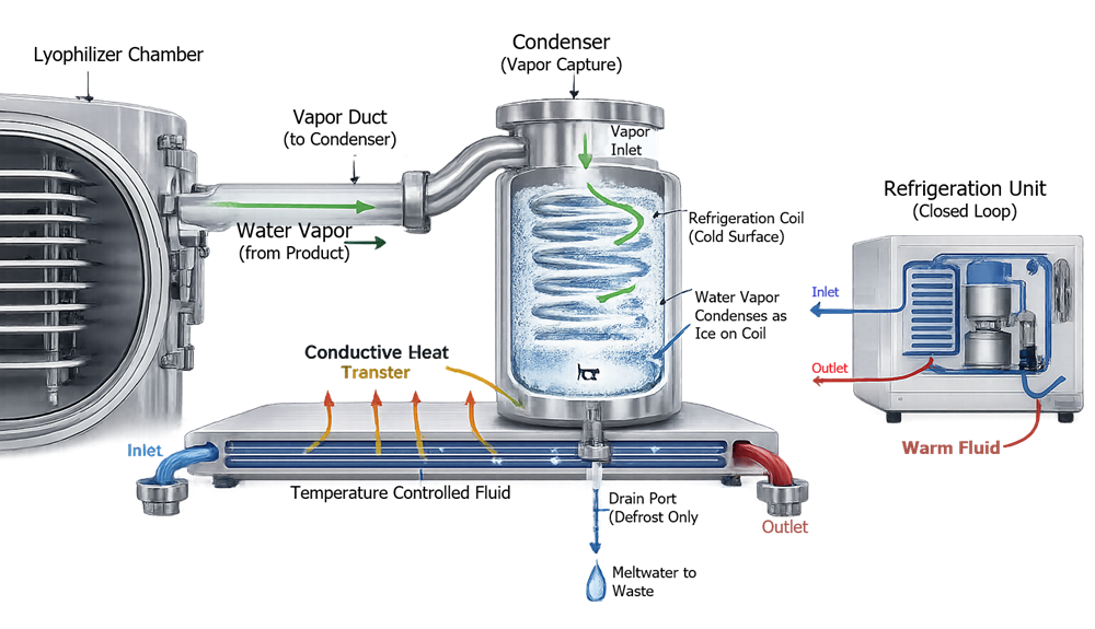
The condenser removes water vapor from the chamber by depositing it as ice on refrigerated surfaces. Its performance depends on more than its minimum temperature.
Critical condenser characteristics include:
- Total ice-holding capacity
- Maximum vapor-capture rate
- Available condensing surface area
- Refrigeration capacity under load
- Temperature distribution
- Defrost capability
- Drainability
- Cleanability
- Isolation from the product chamber where required
Ice Capacity and Sublimation Rate
Two different capabilities should be specified:
- Total ice capacity: the maximum mass of ice that can accumulate during a cycle.
- Peak sublimation capacity: the maximum rate at which vapor can be transported and captured without loss of pressure control.
A condenser may have sufficient total capacity for the batch but still be unable to manage the peak vapor load during aggressive primary drying.
Vapor Duct and Conductance
The vapor path between chamber and condenser should provide adequate conductance across the intended pressure range. Performance can be affected by:
- Duct diameter and length
- Direction changes
- Isolation-valve geometry
- Ice accumulation
- Internal obstructions
- Chamber-to-condenser pressure differential
Restricted vapor flow can increase chamber pressure, limit sublimation, extend drying time, or contribute to product-temperature excursions.
Defrost and Drainage
After drying, accumulated ice must be melted and removed through a controlled defrost sequence. The design should prevent:
- Residual ice remaining before the next cycle
- Uncontrolled re-evaporation into the chamber
- Standing water
- Drain blockage
- Cross-contamination through the drain system
- Unsafe pressure conditions during defrost
Refrigeration System
Refrigeration supports both shelf cooling and condenser operation. Depending on the design, these functions may use shared, separate, staged, or redundant refrigeration circuits.
The system should be sized for the complete operating envelope, including:
- Shelf freezing requirements
- Defined cooling rates
- Minimum shelf temperature
- Condenser pull-down
- Peak vapor load
- Ambient operating conditions
- Maximum product load
- Defrost and recovery requirements
- Simultaneous thermal demands
- Loss of one refrigeration stage where redundancy is claimed
Critical components may include:
- Compressors
- Condensers and evaporators
- Refrigerant control valves
- Heat exchangers
- Thermal-fluid circuits
- Temperature and pressure sensors
- Oil-management components
- Safety switches
- Leak-detection provisions
Refrigerant selection, system obsolescence, environmental requirements, spare-part availability, and supplier support should be evaluated as lifecycle risks.
A redundant compressor or refrigeration circuit provides value only when the control strategy defines how the equipment transitions, alarms, and continues or terminates the cycle following a failure.
Vacuum Generation and Chamber-Pressure Control
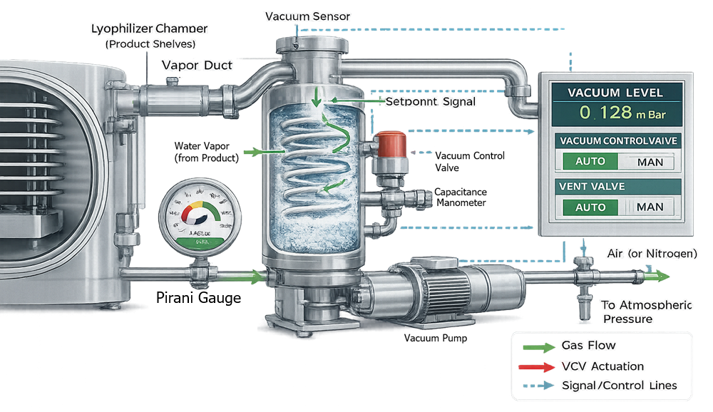
The vacuum system establishes the low-pressure environment required for sublimation and maintains controlled pressure throughout drying.
Typical components include:
- Dry or oil-sealed vacuum pumps
- Booster pumps where required
- Isolation valves
- Throttle or proportional control valves
- Controlled gas-bleed valves
- Vacuum piping
- Mist eliminators or traps where applicable
- Capacitance manometers
- Pirani gauges
- Vacuum-relief and safety devices
Pressure-Control Methods
Chamber pressure may be controlled by:
- Throttling the flow toward the vacuum system
- Introducing a controlled amount of inert gas
- Modulating vacuum-pump capacity
- Combining these approaches
The selected method should provide stable control without excessive oscillation, contamination risk, or disturbance of the dried cake.
Vacuum Measurement
A capacitance manometer provides a gas-independent measurement of absolute pressure and is commonly used as the primary chamber-pressure control reference.
A Pirani gauge measures pressure indirectly through gas thermal conductivity. Its response changes with gas composition and water-vapor concentration. Comparison between Pirani and capacitance-manometer readings can provide useful process information during primary drying and may support endpoint evaluation.
A Pirani gauge is not automatically required for every installation. Instrument selection should reflect the control strategy, endpoint methodology, process range, accuracy requirements, and qualification approach.
Leak Integrity and Noncondensable Gas Load
Leakage and outgassing increase the noncondensable gas load and may cause:
- Extended pull-down time
- Pressure-control instability
- Increased vacuum-pump loading
- Reduced drying efficiency
- Difficulty interpreting endpoint signals
- Potential contamination risk in aseptic service
Chamber construction, door seals, valve seats, instrument connections, piping joints, and mechanical penetrations should support the specified rate-of-rise requirement.
Sterile Venting and Gas Backfill
Lyophilizers used for aseptically processed products commonly require sterile filtered gas for vacuum break, chamber venting, or product backfill.
The gas system may use:
- Nitrogen
- Sterile air
- Another justified process gas
Design considerations include:
- Gas quality
- Filter rating and compatibility
- Filter housing design
- Integrity-test provisions
- Sterilization strategy
- Pressure regulation
- Flow control
- Prevention of reverse flow
- Low-pressure-pressure alarm
- Filter-change controls
- Traceability to the qualified gas system
The gas supply and associated controls should be included in the defined sterile boundary where applicable. Broader requirements are addressed in process gas systems for GMP manufacturing.
Stoppering Mechanism
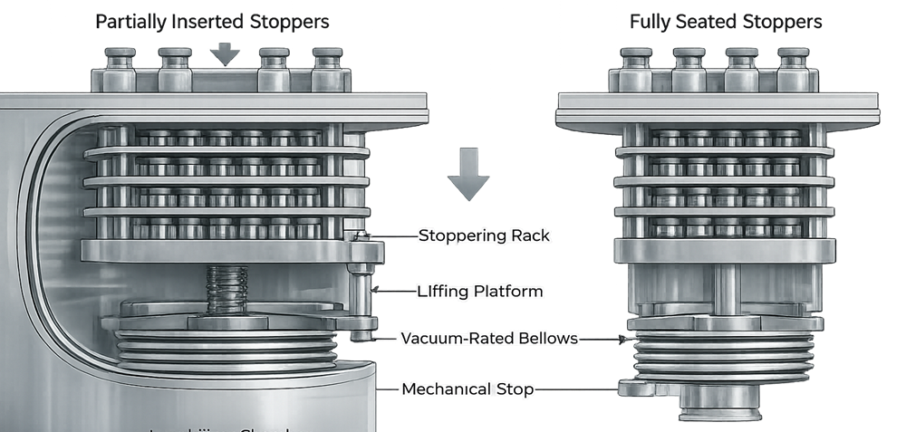
For vial products, partially inserted stoppers permit vapor removal during drying. At the end of the cycle, the shelf stack compresses the stoppers into their final seated position.
The mechanism may use hydraulic, mechanical, or electromechanical actuation. A vacuum-rated bellows or equivalent boundary permits movement without compromising chamber integrity.
Critical design attributes include:
- Shelf-stack alignment
- Controlled vertical travel
- Compression-force capability
- Mechanical travel limits
- Position indication
- Repeatability
- Load distribution
- Vial and stopper compatibility
- Protection against excessive compression
- Prevention of shelf or vial damage
Stoppering may occur under vacuum or after controlled inert-gas backfill. The selected pressure and gas conditions should protect product stability and support the intended container-closure configuration.
The lyophilizer stoppering function seats the stopper but does not complete the entire container-closing process. Downstream controls are addressed in stoppering, capping, and sealing system qualification.
Loading, Unloading, and Aseptic Interfaces
Loading and unloading arrangements may include:
- Manual loading
- Tray-assisted loading
- Semiautomatic push-pull systems
- Automatic loading and unloading systems
- Isolator-integrated systems
- RABS interfaces
- Pass-through lyophilizers connected to separate classified areas
Design review should consider:
- Exposure of partially stoppered vials
- Airflow disruption at the chamber opening
- Door-open duration
- Operator interventions
- Vial accumulation
- Vial breakage and recovery
- Transfer-system cleaning
- Line clearance
- Misaligned or fallen containers
- Communication with the filling-line controls
- Recovery following interrupted transfers
The lyophilizer may form part of the aseptic-processing boundary even though it is a separate equipment package. Loading and unloading interfaces should therefore be coordinated with the aseptic filling line architecture and the site’s aseptic processing validation lifecycle.
Equipment design does not replace aseptic process simulation. Media-fill coverage should represent applicable loading, chamber dwell, partial evacuation, vacuum break, unloading, interventions, and transfer activities.
CIP, SIP, and Sterile-Boundary Integration
Not every lyophilizer has automated CIP or SIP. The required cleaning and sterilization functions depend on intended use, product risk, equipment configuration, and the site contamination-control strategy.
Cleaning Design
Where automated cleaning is provided, design considerations include:
- Spray-device location
- Chamber and condenser coverage
- Shelf exposure
- Cleaning-agent concentration
- Flow, pressure, temperature, and time
- Drainability
- Rinse-water removal
- Prevention of solution retention
- Recipe control
- Verification and sampling access
The design should support the site’s cleaning-validation strategy but does not by itself demonstrate cleaning effectiveness. Broader system architecture is addressed in CIP utility-system design and control.
Steam Sterilization
Where the chamber is steam sterilized, design should support:
- Effective air removal
- Steam access to the complete sterile boundary
- Condensate removal
- Chamber and component heat-up
- Cold-spot monitoring
- Controlled exposure
- Drying after sterilization
- Sterile hold following cycle completion
- Protection against post-sterilization contamination
The sterile boundary may include the chamber, condenser, vapor duct, drains, vent filters, gas lines, valves, instrument connections, and associated piping. Boundary diagrams should explicitly identify which surfaces are sterilized and which remain outside the sterilized volume.
Detailed utility and cycle considerations are addressed in SIP utility systems.
Instrumentation and Measurement Architecture
Critical instrumentation may include:
- Shelf inlet and outlet temperature sensors
- Individual shelf temperature sensors
- Condenser temperature sensors
- Chamber temperature sensors
- Product thermocouples or resistance-temperature detectors
- Capacitance manometer
- Pirani gauge
- Thermal-fluid flow and pressure instruments
- Hydraulic pressure instruments
- Sterilization temperature sensors
- Clean-steam pressure instruments
- Gas-supply pressure and flow instruments
- Valve and door position feedback
- Shelf-position indication
Instrument requirements should define:
- Measurement range
- Accuracy
- Resolution
- Response time
- Installation location
- Calibration range and points
- Alarm and interlock function
- Data-recording frequency
- Failure response
- Replacement and configuration controls
Instruments used for process control, alarms, qualification, or batch decisions should be managed through the applicable GMP calibration program and metrology control.
Automation and Control Architecture
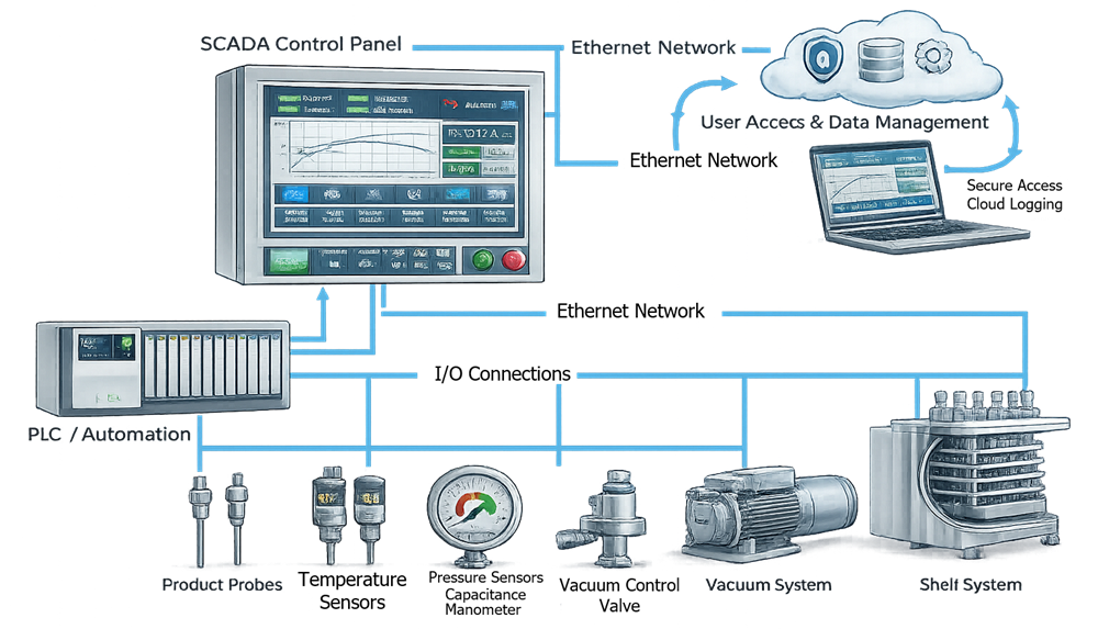
The lyophilizer control system coordinates recipes, shelf temperature, chamber pressure, condenser operation, vacuum generation, gas backfill, stoppering, defrost, cleaning, sterilization, alarms, and equipment-state transitions.
The computerized-system boundary may include:
- PLC
- HMI
- Recipe-management functions
- Data historian
- Batch-report generation
- Audit-trail functions
- User and role management
- Network interfaces
- Remote supplier access
- Time synchronization
- Backup and restoration
- Interfaces with filling-line or site systems
Recipe Control
Recipes may contain:
- Shelf-temperature setpoints
- Ramp rates
- Hold times
- Chamber-pressure setpoints
- Phase-transition criteria
- Condenser requirements
- Vacuum-break parameters
- Backfill pressure
- Stoppering sequence
- Alarm delays and limits
Recipe creation, modification, approval, use, and retirement should be controlled. The system should preserve the identity and version of the recipe used for each executed batch.
Alarms, Interlocks, and Safe States
Design should address conditions such as:
- Loss of vacuum
- High chamber pressure
- Shelf-temperature deviation
- Condenser-temperature excursion
- Refrigeration failure
- Thermal-fluid flow failure
- Door or valve position disagreement
- Loss of sterile-gas pressure
- Stoppering-system failure
- Utility interruption
- Instrument failure
- Power loss
- Communication or data-recording failure
Interlocks should prevent unsafe or incompatible equipment states. The failure response should be defined instead of assuming that every interruption requires the same automatic shutdown.
Electronic Records
Where electronic records support GMP decisions, controls should address:
- Unique user accounts
- Role-based access
- Audit trails
- Recipe and setpoint changes
- Secure time-stamped records
- Data retention
- Backup and restoration
- Reviewable alarm and event history
- Protection against unauthorized deletion or overwriting
General electronic-record expectations are addressed in Part 11 compliance and electronic-record controls.
Utilities and Facility Interfaces
Utility requirements should be defined for the actual lyophilizer configuration. Potential interfaces include:
- Electrical power
- Emergency or uninterruptible power
- Cooling water
- Chilled water
- Refrigerant systems
- Compressed air
- Nitrogen or sterile air
- Clean steam
- Purified water or water for injection
- CIP supply and return
- Process vacuum
- Exhaust
- Condensate and defrost drains
- Hydraulic systems
- Facility automation and network connections
The URS should define normal operating requirements, allowable variability, alarm conditions, recovery expectations, and system behavior following loss of each critical utility. Requirements development is addressed in URS for GMP facilities, utilities, and equipment.
Critical Components and Design Risks
| Component or function | Principal design concern | Potential consequence |
|---|---|---|
| Chamber and door | Vacuum integrity and structural capability | Leakage, unstable pressure, unsafe operation |
| Door gasket | Compatibility and repeatable sealing | Failed leak tests or contamination risk |
| Shelves | Flatness and temperature uniformity | Product-temperature and stoppering variability |
| Thermal-fluid system | Flow distribution and leak containment | Uneven heating or chamber contamination |
| Condenser | Ice capacity and peak capture rate | Pressure instability or extended drying |
| Vapor duct | Adequate conductance | Restricted sublimation and scale-up difficulty |
| Refrigeration | Capacity across expected loads | Inability to freeze or condense adequately |
| Vacuum pumps | Pull-down and noncondensable-gas capacity | Slow evacuation or poor pressure control |
| Pressure-control valve | Stable modulation | Oscillation or pressure excursions |
| Pressure instruments | Accuracy and suitable measurement principle | Incorrect control or endpoint interpretation |
| Sterile-gas system | Filtration and boundary integrity | Post-sterilization contamination |
| Stoppering system | Alignment and travel repeatability | Incomplete seating or vial damage |
| CIP system | Coverage and drainage | Residue retention or ineffective cleaning |
| SIP system | Air removal and condensate control | Inadequate sterilization |
| Automation | State control and configuration management | Incorrect sequence or unreconstructable batch |
| Loading system | Container control and aseptic protection | Vial damage or contamination exposure |
Design risks should be evaluated during supplier selection and design review. Controls may include design changes, redundancy, monitoring, alarms, preventive maintenance, spare parts, inspection, qualification testing, and procedural controls.
Supplier Documentation and Design Review
The supplier documentation package should support design assessment, installation, qualification, maintenance, and future troubleshooting.
Expected documents may include:
- Approved specifications
- General arrangement drawings
- Piping and instrumentation diagrams
- Chamber and pressure-vessel records
- Material certificates
- Weld and surface-finish documentation
- Shelf and condenser design data
- Refrigeration calculations
- Vacuum-system calculations
- Utility requirements
- Instrument lists and data sheets
- Valve lists
- Electrical drawings
- Control narratives
- Software and hardware inventories
- Alarm and interlock lists
- Recipe parameter lists
- Network architecture
- Operating and maintenance manuals
- Recommended spare-parts lists
- FAT and SAT records
- Cleaning and sterilization documentation
Design review should confirm that the documented configuration satisfies approved requirements and that critical features are testable. General lifecycle expectations for design confirmation are addressed in design qualification.
Maintenance and Lifecycle Considerations
The design should provide safe access for inspection, calibration, repair, and replacement of critical components. Particular attention should be given to:
- Door and valve seals
- Vacuum pumps
- Refrigeration compressors
- Thermal-fluid pumps
- Hydraulic systems
- Flexible hoses and bellows
- Sterile-gas filters
- Pressure instruments
- Temperature sensors
- Shelf-position components
- Control-system hardware
- Refrigerant and thermal-fluid leaks
- Obsolescence of proprietary components
Maintenance activities can affect chamber integrity, calibration status, sterile boundaries, refrigeration capacity, pressure control, and computerized configuration. The post-maintenance verification requirement should be defined according to component function and risk. Program-level controls are addressed in preventive maintenance and system reliability.
Relationship to Qualification and Process Validation
Lyophilizer design establishes the equipment capabilities and operating limits that later qualification must verify.
Lyophilizer system qualification should demonstrate, as applicable:
- Conformance to approved design
- Correct installation
- Shelf-temperature range and uniformity
- Ramp-rate performance
- Chamber-pressure control
- Vacuum pull-down and leak rate
- Condenser temperature and capacity
- Defrost and drainage
- Stoppering performance
- Alarm and interlock functions
- Cleaning and sterilization functions
- Electronic-record and security controls
Lyophilization process qualification subsequently demonstrates that the qualified equipment, product formulation, container-closure system, load configuration, and approved cycle operate together reproducibly.
A qualified lyophilizer does not establish that every product cycle is validated. Conversely, successful product testing cannot compensate for unverified equipment capability or unresolved design deficiencies.
Summary
A pharmaceutical lyophilizer is an integrated thermal, vacuum, refrigeration, mechanical, sterile-processing, and computerized system. Reliable performance depends on coordinated design of the chamber, shelves, condenser, vapor path, refrigeration, vacuum control, instrumentation, stoppering mechanism, utilities, automation, and aseptic interfaces.
Design documentation should define the operating envelope, critical components, system boundaries, failure responses, maintenance requirements, and qualification strategy before the equipment is released for GMP use.