

Tablet Compression Equipment: Design, Controls, and Qualification
Tablet compression equipment converts a controlled quantity of powder or granules into tablets by filling die cavities and applying mechanical force through matched punches and dies. Press design and operation affect tablet weight, thickness, density, hardness, friability, appearance, and other physical characteristics.
The press does not create active-ingredient uniformity within an inadequately blended formulation. Upstream blending, material transfer, hopper behavior, feed-frame operation, and die filling must work together to preserve formulation uniformity and deliver a consistent mass to each die.
Equipment qualification demonstrates that the tablet press is properly designed, installed, and capable of operating throughout its approved ranges. Product-specific process development, process performance qualification, and continued process verification must demonstrate that the integrated compression process consistently produces acceptable tablets.
Purpose and scope
This article addresses:
- Single-station and rotary tablet presses
- Material feeding and die filling
- Turret, punches, dies, cams, and compression rollers
- Pre-compression, main compression, decompression, ejection, and tablet discharge
- Compression force, fill depth, turret speed, dwell time, and ejection force
- Tooling control
- Automated weight control, sampling, testing, and rejection
- Common tablet defects
- Containment, cleaning, and equipment integration
- Automation and electronic records
- URS, DQ, supplier documentation, FAT, SAT, IQ, OQ, and equipment-level PQ
- Product-specific PPQ and continued verification boundaries
- Calibration, maintenance, change control, periodic review, and requalification
The article does not establish formulation-specific compression parameters, tablet specifications, pharmacopoeial acceptance criteria, PPQ batch quantities, or routine in-process sampling frequencies.
Position within solid dosage manufacturing
Tablet compression normally follows material dispensing, milling, granulation or direct-blend preparation, drying where applicable, and final blending.
Upstream operations may include:
- Dispensing and material handling
- Pharmaceutical milling
- Solid dosage blending
- Pharmaceutical granulation
- Pharmaceutical drying
After compression, tablets may pass through:
- Dedusting
- Metal detection
- In-process inspection and reject systems
- Tablet coating
- Packaging
The illustration below shows one representative solid dosage equipment train from granulation through tablet handling and packaging.

The qualified compression-system boundary should include the upstream and downstream interfaces that can affect press feeding, tablet rejection, product segregation, contamination control, or batch accountability.
Tablet compression sequence
A rotary tablet press performs a repeated mechanical sequence at each station:
- Material enters the feed frame.
- The lower punch moves to establish the die-filling position.
- Material fills the die cavity.
- Excess material is removed as the lower punch moves to the dosing position.
- Pre-compression may remove entrapped air and begin consolidation.
- Main compression produces the required tablet structure.
- Compression force is released.
- The upper punch withdraws.
- The lower punch rises to eject the tablet.
- The take-off blade directs the tablet into the discharge path.
- The lower punch returns to the filling position.
The illustration below presents the principal stages of feeding, filling, compression, and ejection.
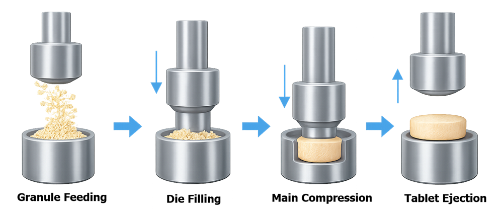
Actual rotary presses include additional cam movements, punch-guidance stages, lubrication points, monitoring functions, and reject controls not represented in the simplified illustration.
Types of tablet presses
Single-station presses
A single-station press uses one upper punch, one lower punch, and one die. It produces one tablet during each machine cycle.
The illustration below shows a representative single-station tablet press used for development or small-scale production.
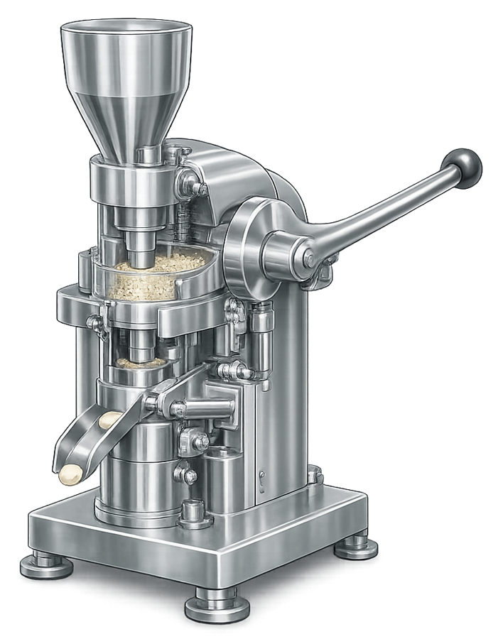
Single-station presses may be used for:
- Formulation development
- Tooling trials
- Compression studies
- Small-scale production
- Investigation of compaction behavior
- Production of specialized low-volume products
Results from a single-station press may not directly predict performance on a high-speed rotary press. Differences may include dwell time, feeding, deaeration, compression profile, punch velocity, ejection, heat generation, and material residence time.
Rotary tablet presses
A rotary press contains multiple punch-and-die stations arranged around a rotating turret. Each station passes through filling, dosing, compression, ejection, and discharge positions during each turret revolution.
The illustration below shows a representative production rotary tablet press with enclosed compression and control areas.
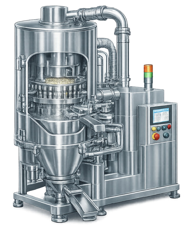
Rotary presses may include:
- One or more filling locations
- Multiple pre-compression or compression stages
- Force feeders
- Compression-force monitoring
- Automatic fill-depth adjustment
- Automated tablet sampling
- Integrated hardness, thickness, and weight testing
- Station-specific monitoring
- Automatic tablet rejection
- Tooling-protection systems
- Wash-in-place or contained-cleaning features
Production capability depends on the number of stations, turret speed, tooling, tablet size, material behavior, feeder performance, compression-force requirements, and downstream equipment capacity.
System boundaries and major components
The tablet press boundary may include:
- Material hopper
- Level sensor
- Transfer or charging connection
- Gravity or force feeder
- Feed frame and paddles
- Turret
- Die table
- Upper and lower punches
- Dies
- Punch guides
- Fill, dosing, compression, and ejection cams
- Pre-compression and main-compression rollers
- Fill-depth and thickness adjustment mechanisms
- Tablet take-off blade
- Discharge chute
- Reject gate
- Lubrication system
- Dust-extraction connections
- Press enclosure
- Control system
- Compression-force instrumentation
- Automated sampler
- Tablet tester
- Deduster
- Metal detector
- Contained product-transfer interfaces
The GMP boundary, cleaning boundary, safety boundary, and computerized-system boundary should each be defined. They may overlap without being identical.
Material feeding and die filling
Hopper and material supply
The hopper supplies material to the feed frame. Product level and powder head can influence material delivery and die filling. Design and operating controls may address:
- Hopper geometry
- Minimum and maximum level
- Refill method
- Material residence time
- Powder bridging
- Rat-holing
- Segregation
- Electrostatic behavior
- Dust generation
- Interaction with an upstream bin or vacuum-transfer system
An unstable material level may alter feed conditions even when press speed and fill depth remain unchanged.
Feed frame
A gravity feeder relies primarily on material flow and turret movement. A force feeder uses rotating paddles to move material across the die table and into the dies. Potentially important feeder variables include:
- Paddle speed
- Paddle direction
- Paddle geometry
- Feed-frame clearance
- Material level
- Residence time
- Turret speed
- Seal condition
- Dust extraction
Aggressive feeder operation may cause particle attrition, segregation, heat generation, lubricant redistribution, or granule densification. Inadequate feeder operation may produce inconsistent die filling.
Die fill and dosing
Lower-punch position establishes available die volume during filling and dosing. Fill depth is therefore a primary mechanical control over tablet mass. Tablet weight also depends on:
- Material bulk density
- Flowability
- Feeder operation
- Turret speed
- Die-fill time
- Hopper level
- Vibration
- Entrained air
- Tooling condition
A fixed fill-depth setting does not guarantee constant tablet weight when material properties or feeding conditions change.
Turret, punches, dies, and cams
The turret carries the punches and dies through the compression cycle. Punch motion is controlled by stationary cams and compression rollers. Critical mechanical considerations include:
- Turret alignment
- Punch-guide condition
- Die-pocket condition
- Cam condition
- Compression-roller alignment
- Punch-head lubrication
- Turret lubrication
- Gearbox condition
- Runout
- Vibration
- Mechanical clearances
Abnormal wear or misalignment may cause force variation, tooling damage, binding, tablet defects, or metal contamination.
Tooling design and control
A tablet tooling set includes an upper punch, lower punch, and die. Punch-tip geometry determines tablet shape, cup profile, score, break line, and embossed identification. The illustration below identifies the principal components of a tablet punch-and-die assembly.
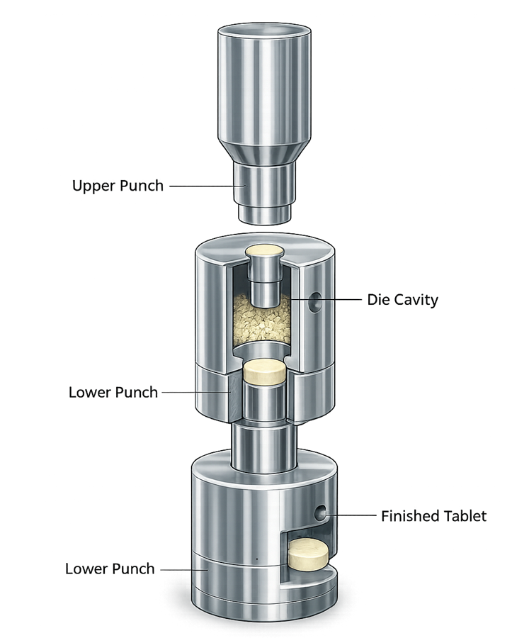
Tooling control should address:
- Tooling type and dimensions
- Press compatibility
- Tool identification
- Punch and die matching
- Working length
- Tip condition
- Cup depth and profile
- Embossing and score orientation
- Keyed-punch orientation
- Wear limits
- Corrosion
- Surface treatment or coating
- Cleaning
- Lubrication
- Storage
- Installation
- Inspection frequency
- Tooling-life history
Worn punches or dies may change tablet dimensions, weight, appearance, ejection force, or compression behavior before a visible catastrophic failure occurs.
Tooling replacement with a nominally equivalent design should be assessed when dimensional tolerances, materials, coatings, cup profiles, embossing, or working length could affect the process.
Pre-compression and main compression
Pre-compression applies an initial force before the main-compression event. It can support particle rearrangement, deaeration, and initial consolidation. Main compression applies the force required to form the final compact.
The illustration below compares pre-compression and main-compression stages within a rotary press.
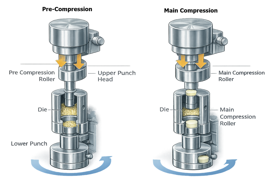
Important parameters may include:
- Pre-compression force
- Main-compression force
- Punch penetration
- Tablet thickness setting
- Turret speed
- Compression-roller position
- Dwell time
- Decompression profile
Higher compression force does not universally produce a better tablet. Excessive force may cause over-compaction, tooling stress, extended disintegration, reduced dissolution, capping, lamination, or other material-dependent effects.
Dwell time and compression profile
Dwell time is the period during which the punch head is exposed to the compression roller’s effective constant-thickness region. It is influenced by:
- Turret speed
- Punch-head geometry
- Compression-roller geometry
- Press design
Dwell time is not always an independently adjustable setting. Increasing production speed generally reduces the time available for material rearrangement, deaeration, consolidation, and stress relaxation.
Scale-up from a development press should consider compression-force profile and dwell time rather than relying only on nominal compression force.
Ejection and tablet take-off
Following decompression, the lower punch rises and ejects the tablet from the die. The take-off blade moves the tablet into the discharge path.
Ejection performance may be affected by:
- Die-wall friction
- Lubricant distribution
- Tooling surface condition
- Tablet geometry
- Product moisture
- Compression force
- Lower-punch movement
- Ejection-cam condition
- Take-off-blade setup
Elevated or increasing ejection force may indicate inadequate lubrication, sticking, binding, die wear, contamination, or changing material conditions.
The discharge system should prevent tablet damage, uncontrolled accumulation, cross-contamination, and mixing of accepted and rejected tablets.
Critical process parameters and equipment responses
| Parameter or condition | Principal equipment function | Potential product or process response |
|---|---|---|
| Turret speed | Establishes production rate and influences dwell and fill time | Weight variation, compression behavior, defects |
| Fill depth | Establishes die volume | Tablet weight |
| Feeder speed | Controls material movement into dies | Die filling, segregation, attrition |
| Hopper level | Influences material head and supply | Feeding consistency |
| Pre-compression force | Supports deaeration and initial consolidation | Capping, lamination, compact formation |
| Main-compression force | Produces final compaction | Hardness, thickness, friability, disintegration |
| Punch penetration | Establishes compression position and geometry | Tablet structure and thickness |
| Ejection force | Indicates resistance during removal | Sticking, binding, tooling condition |
| Tooling condition | Defines die volume, shape, surface, and movement | Weight, appearance, dimensions, defects |
| Dust extraction | Removes airborne material | Containment, product loss, feeder behavior |
Product-specific parameter ranges must be established through formulation and process development. Equipment qualification verifies that the press can achieve, control, and record the ranges assigned to it.
Compression-force monitoring
Compression-force instruments commonly use strain gauges or load cells associated with compression rollers or support structures. The monitoring system may provide:
- Individual compression-event values
- Station-specific trends
- Average force
- Minimum and maximum force
- Force variability
- Alarm limits
- Reject limits
- Tooling-overload protection
Compression force may correlate with tablet weight when formulation properties and filling behavior remain sufficiently consistent. It is an indirect measurement and should not automatically be treated as a direct tablet-weight measurement.
A compression-force-based weight-control system requires a justified control relationship, suitable limits, controlled material conditions, and verification against actual tablet weights.
Tablet weight control
Tablet weight may be controlled through:
- Fill-depth adjustment
- Compression-force feedback
- Feedback from an automated tablet tester
- Scheduled operator sampling
- A combination of these controls
The control strategy should define:
- Measurement frequency
- Number of tablets
- Adjustment logic
- Adjustment limits
- Alarm limits
- Reject limits
- Response to failed measurement
- Treatment of tablets produced during adjustment
- Data recording
- Operator authority
Automatic correction should not conceal an unstable process. Frequent adjustment may indicate inconsistent feed, material segregation, changing bulk density, tooling wear, or another assignable cause.
Automated sampling and tablet testing
An integrated tablet sampler may transfer tablets to a tester that measures:
- Weight
- Thickness
- Diameter
- Hardness or breaking force
The system boundary may include:
- Sampling chute
- Diverter
- Sample transport
- Tablet orientation
- Tester
- Calibration weights or reference devices
- Cleaning provisions
- Data interface
- Return or destruction of sampled tablets
Qualification should verify correct sample identification, transfer, measurement, calculation, result transmission, press response, alarm generation, and record retention. Sampler or tester malfunctions must not permit unassessed tablets to continue indefinitely without a defined response.
Automatic reject systems
The press may reject tablets based on:
- Compression-force limits
- Machine startup or shutdown
- Parameter adjustment
- Feeder interruption
- Low hopper level
- Tooling overload
- Tester failure
- Failed weight, hardness, or thickness result
- Metal-detector signal
- Manual operator command
Reject controls should ensure that:
- Reject criteria are defined
- Reject timing accounts for transport delay
- The gate moves to the correct position
- Rejected tablets reach the designated container
- Accepted and rejected tablets cannot remix
- Reject containers remain identified and secured
- Reject events are recorded
- Batch reconciliation remains possible
Challenge testing should represent different press speeds and relevant delay conditions.
Tablet defects and process signals
Common defects include:
- Capping
- Lamination
- Sticking
- Picking
- Chipping
- Cracking
- Binding
- Mottling
- Double impression
- Weight variation
- Excessive friability
- Inconsistent thickness
The illustration below shows representative visible defects associated with formulation, tooling, feeding, compression, and ejection conditions.
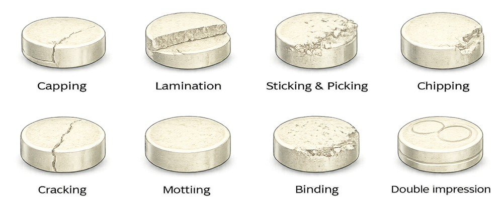
A defect should not be assigned automatically to a single equipment parameter. Similar defects may result from different causes.
| Defect or signal | Possible contributors |
|---|---|
| Capping or lamination | Entrapped air, excessive speed, inadequate pre-compression, material properties, over-dry granules |
| Sticking or picking | Product moisture, tooling surface, inadequate lubrication, heat, embossing geometry |
| Chipping or cracking | Weak compact, poor ejection, worn tooling, formulation condition |
| Binding or high ejection force | Die-wall friction, inadequate lubrication, tooling wear, contamination |
| Weight variation | Feed inconsistency, segregation, hopper level, fill time, tooling variation |
| Double impression | Free rotation of embossed punches or inadequate keyed-punch control |
| Hardness variation | Compression-force variation, weight variation, material variability |
| Excessive force variability | Feeding instability, station condition, tooling wear, material segregation |
Investigation should consider equipment, tooling, material, method, environment, measurement, and operator factors.
Product attributes and process validation
Tablet compression may influence:
- Tablet weight
- Thickness
- Breaking force
- Tensile strength
- Friability
- Disintegration
- Dissolution
- Porosity
- Appearance
- Defect rate
Content uniformity depends on formulation uniformity, segregation control, consistent die fill, and tablet mass. A tablet press cannot correct nonuniform API distribution in the incoming blend.
Not every product attribute must be measured by the press. The control strategy should identify which attributes are monitored in-process, tested off-line, evaluated during PPQ, or included in routine release testing.
Containment and dust control
Tablet compression generates dust through feeding, die filling, turret movement, compression, ejection, dedusting, and cleaning.
Controls may include:
- Enclosed compression zones
- Local dust extraction
- Negative-pressure operation
- Sealed product transfer
- Contained hopper connections
- Split butterfly valves
- Glove ports
- Isolator enclosures
- Safe-change filters
- Wash-in-place systems
- Contained tooling removal
Dust extraction should be balanced. Inadequate extraction may impair containment and mechanical operation. Excessive extraction near the feed frame may remove product or disrupt die filling.
The associated pharmaceutical powder containment and dust collection systems article addresses dust-extraction architecture, airflow, filtration, monitoring, and qualification.
Hygienic design and cleaning
Product-contact and residue-retaining areas may include:
- Hopper
- Feed frame
- Paddles
- Feed-frame seals
- Die table
- Turret surfaces
- Punch guides
- Dies and punches
- Take-off blade
- Discharge chute
- Reject gate
- Sampling system
- Deduster
- Transfer connections
- Dust boots and extraction interfaces
Cleaning design should support:
- Safe access
- Defined disassembly
- Component identification
- Visual inspection
- Drainage and drying where wet cleaning is used
- Correct reassembly
- Protection of cleaned tooling and components
- Prevention of lubricant contamination
Equipment qualification may verify wash functions, component removal, assembly checks, cleaning sequences, and drainage. It does not replace the residue limits, sampling recovery, analytical capability, worst-case selection, and reproducibility required by the site’s cleaning validation approach.
Instrumentation and automation
Tablet-press instrumentation may include:
- Turret-speed measurement
- Feeder-speed measurement
- Compression-force sensors
- Ejection-force sensors
- Position encoders
- Hopper-level sensors
- Motor-current monitoring
- Temperature sensors
- Pressure or vacuum instruments
- Dust-extraction monitoring
- Tablet-test instruments
Automated functions may include:
- Recipe management
- Speed control
- Fill-depth adjustment
- Compression-force control
- Weight-control feedback
- Sampling
- Tablet testing
- Alarm management
- Rejection
- Tooling protection
- Batch reporting
- Electronic records
The computerized-system boundary should identify controllers, operator interfaces, drives, sensors, tablet testers, databases, network interfaces, historian functions, and connected manufacturing systems.
Controls should address:
- Authorized access
- Recipe approval
- Parameter limits
- Manual-mode restrictions
- Audit trails where applicable
- Data accuracy
- Time synchronization
- Backup and recovery
- Configuration control
- Software changes
- Interface verification
User requirements and design qualification
The URS should define measurable requirements for:
- Intended products
- Tablet dimensions and geometry
- Tooling type
- Number of stations
- Production-rate range
- Turret-speed range
- Pre-compression and main-compression capability
- Force and ejection monitoring
- Feed-frame design
- Hopper and charging arrangement
- Sampling and tablet testing
- Reject functions
- Containment
- Cleaning
- Product-contact materials
- Automation and electronic records
- Deduster and metal-detector interfaces
- Maintenance access
- Supplier documentation
Design qualification should confirm that the selected press and supporting systems satisfy intended use and adequately control identified risks.
Supplier documentation, FAT, and SAT
Supplier documentation may include:
- General arrangement drawings
- Product-contact drawings
- Tooling specifications
- Mechanical drawings
- Electrical drawings
- Instrument lists
- Functional specifications
- Software and configuration documentation
- Alarm and interlock lists
- Lubrication requirements
- Cleaning instructions
- Maintenance recommendations
- Spare-parts lists
- Calibration procedures
- Operating manuals
Factory acceptance testing may verify:
- Mechanical operation
- Turret and feeder speed
- Compression-force functions
- Tooling protection
- Recipes
- Alarms and interlocks
- Reject logic
- Automated sampling
- Tablet-tester communication
- Data recording
- Safety functions
Site acceptance testing should confirm condition after delivery and operation with installed utilities, dust extraction, upstream feeding, downstream equipment, and site interfaces.
Approved FAT results may support qualification when they remain applicable and traceable. Site verification remains necessary for functions affected by shipment, installation, utilities, configuration, or integration.
Installation qualification
Installation qualification should verify, as applicable:
- Equipment identity and location
- Mechanical installation
- Turret and tooling configuration
- Feed frame
- Compression rollers and cams
- Guards and enclosures
- Hopper and material-transfer interfaces
- Deduster, sampler, tester, and reject system
- Dust-extraction connections
- Utilities
- Product-contact materials
- Lubricants
- Instruments and calibration status
- Control hardware
- Software and firmware versions
- Drawings and manuals
- Cleaning and maintenance requirements
Installation discrepancies should be documented and assessed before release.
Operational qualification
Operational qualification should challenge the press throughout its approved equipment ranges.
Testing may include:
- Minimum and maximum turret speed
- Feeder-speed range
- Fill-depth adjustment
- Pre-compression and main-compression adjustment
- Compression-force measurement
- Ejection-force monitoring
- Loaded or simulated-load operation
- Tooling-protection functions
- Sampler operation
- Tablet-tester functions
- Reject timing and destination
- Alarm and interlock challenges
- Guard switches
- Emergency stopping
- Manual and automatic modes
- Recipe limits
- Power-loss and restart behavior
- Data recording
- Interface communication
Product-specific hardness, friability, dissolution, content uniformity, or other commercial tablet criteria should not be assigned as generic equipment OQ acceptance criteria.
Equipment-level performance qualification
Equipment-level PQ demonstrates that the installed press can perform its intended equipment functions reproducibly under representative operating conditions. Testing may evaluate:
- Sustained operation at representative rates
- Minimum and maximum intended tooling or press configurations
- Repeatable feeding and die filling
- Compression-force measurement and control
- Automatic adjustment
- Sampling and tablet testing
- Reject performance
- Charging and discharge
- Deduster and metal-detector integration
- Material recovery
- Containment
- Cleaning functionality
- Repeated recipe execution
A suitable placebo, surrogate, or representative material may be used when it provides an appropriate mechanical and feeding challenge.
Equipment-level PQ does not demonstrate that a commercial formulation consistently produces tablets meeting product specifications. That conclusion requires product-specific PPQ.
Product-specific PPQ and sampling
Product-specific PPQ evaluates the integrated commercial manufacturing process using the approved formulation, equipment, operating strategy, analytical methods, and sampling plan. PPQ may evaluate:
- Tablet weight
- Thickness
- Breaking force or hardness
- Friability
- Disintegration
- Dissolution
- Content uniformity
- Appearance
- Defect rate
- Compression-force trends
- Ejection-force trends
- Reject rate
- Yield and reconciliation
- Performance after process interruptions
Sampling should represent meaningful periods and conditions across the compression run.
The illustration below shows a conceptual tablet-sampling timeline. The displayed quantities and intervals are examples only and must not be copied as universal requirements.
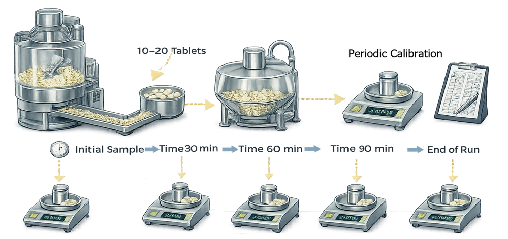
A justified PPQ sampling plan may include:
- Startup
- Established operation
- Defined time intervals
- Hopper replenishment
- Speed or parameter adjustment
- Restart after interruption
- Multiple press stations where relevant
- End of batch
- Early, middle, and late discharge
- Accepted and rejected tablet reconciliation
Sampling strategy is addressed further in sampling plan and data collection strategy.
Equipment qualification versus process validation
| Equipment qualification | Product-specific process validation |
|---|---|
| Confirms press installation and configuration | Confirms the commercial formulation and manufacturing process |
| Verifies speed, force, position, sampling, testing, alarms, and rejection | Establishes formulation-specific operating ranges |
| Challenges approved equipment ranges | Challenges material and process variability |
| Demonstrates mechanical and control repeatability | Demonstrates consistent tablet quality |
| May use suitable surrogate material | Uses justified commercial-process conditions |
| Does not establish content uniformity or dissolution | Evaluates applicable product attributes |
| Does not determine PPQ batch requirements | Establishes PPQ and continued-verification evidence |
The broader lifecycle is addressed in PPQ strategy and batch definition and general principles of process validation.
Calibration and maintenance
Instruments used to control, record, test, or make GMP decisions should be included in the applicable calibration program and metrology control.
Relevant devices may include:
- Compression-force sensors
- Ejection-force sensors
- Speed indicators
- Position encoders
- Timers
- Load cells
- Automated tablet testers
- Reference weights
- Thickness instruments
- Hardness or breaking-force instruments
- Dust-extraction instruments
Preventive maintenance should address:
- Turret
- Gearbox
- Bearings
- Compression rollers
- Cams
- Punch guides
- Lubrication system
- Feed frame
- Paddles
- Seals
- Take-off blade
- Reject gate
- Sampler
- Tablet tester
- Enclosures
- Dust-extraction connections
Broader principles are addressed in preventive maintenance and equipment reliability.
Common equipment failure modes
| Failure mode | Potential effect | Typical detection or control |
|---|---|---|
| Feeder malfunction | Weight variation or interrupted die fill | Speed feedback, motor monitoring, inspection |
| Unstable hopper level | Variable feeding conditions | Level alarm and refill control |
| Compression-force sensor drift | Incorrect control or rejection | Calibration, verification, trend review |
| Worn tooling | Weight, dimension, appearance, or ejection changes | Tooling inspection and lifecycle records |
| High ejection force | Sticking, binding, tooling damage | Ejection-force monitoring and alarm |
| Reject-gate failure | Nonconforming tablets enter accepted stream | Challenge testing and position confirmation |
| Incorrect tooling installed | Wrong tablet dimensions or imprint | Tooling identification and line clearance |
| Excessive dust extraction | Material loss or disturbed die filling | Airflow balancing and operating limits |
| Sampler or tester failure | Loss of in-process verification | Alarm and defined fallback procedure |
| Wrong recipe | Operation outside approved conditions | Access control and recipe approval |
| Lubrication failure | Wear, binding, or contamination risk | Preventive maintenance and inspection |
| Software or configuration change | Loss of validated control behavior | Change control and configuration management |
Change control and requalification
Changes should be assessed for effects on equipment qualification and the validated compression process.
Examples include:
- New tooling type or tablet geometry
- New feed-frame or paddle configuration
- Turret, cam, or compression-roller replacement
- Compression-force sensor replacement
- New speed or force range
- Tablet-tester replacement
- Reject-system modification
- Control-software change
- Recipe change
- Hopper or charging-system modification
- Deduster or metal-detector change
- Dust-extraction modification
- Cleaning-process change
- Major repair
- Equipment relocation
The impact assessment should determine whether the change requires:
- Document revision
- Calibration or functional testing
- Targeted IQ or OQ
- Equipment-level PQ
- Tooling studies
- Cleaning assessment
- Product-development work
- Additional PPQ or process validation
Requalification should focus on affected functions and risks rather than automatically repeating every original test.
Periodic review and continued verification
Periodic equipment review should evaluate:
- Qualification status
- Changes
- Deviations
- Alarms
- Calibration
- Maintenance
- Tooling history
- Reject-system performance
- Software and recipe status
- Recurring failures
- Cleaning performance
- Supplier support
- Obsolescence
- Requalification decisions
Product continued verification should separately evaluate relevant process and quality trends, including tablet weight, force, hardness, thickness, defects, rejects, yield, dissolution, content uniformity, and other applicable attributes.
Documentation and traceability
Lifecycle documentation should connect:
- Intended use
- User requirements
- Design specifications
- Risk assessments
- Supplier documentation
- FAT and SAT
- IQ, OQ, and equipment-level PQ
- Instruments and calibration
- Tooling inventory and inspection
- Automation configuration
- Recipes
- Reject logic
- Cleaning procedures
- Maintenance
- Training
- Deviations
- Change controls
- Requalification decisions
- Product-development studies
- PPQ
- Continued process verification
The documentation should distinguish evidence of tablet-press capability from evidence validating the product-specific manufacturing process.
Regulatory basis
21 CFR 211.63 requires equipment to be appropriately designed, adequately sized, and suitably located for intended use, cleaning, and maintenance.
21 CFR 211.67 establishes requirements for equipment cleaning, maintenance, written procedures, and records.
21 CFR 211.68 addresses automatic, mechanical, electronic, and computerized equipment, including calibration, inspection, checks, and system controls.
21 CFR 211.110 identifies tablet or capsule weight variation, adequacy of mixing, dissolution, and other appropriate in-process controls used to assure batch uniformity and integrity.
FDA’s Process Validation: General Principles and Practices separates equipment qualification from process performance qualification and continued process verification.
Conclusion
Tablet compression equipment must provide controlled material feeding, die filling, compression, decompression, ejection, tablet discharge, sampling, testing, rejection, and data capture.
Qualification demonstrates that the installed press can operate reproducibly throughout its approved equipment ranges. It does not establish product-specific compression parameters or prove that a commercial formulation consistently meets tablet-quality requirements.
Product development, PPQ, and continued verification must demonstrate control of the integrated process from final blend transfer through tablet compression and downstream handling.