

Pharmaceutical Water System Design and Distribution
A pharmaceutical water system must consistently produce and deliver water of the required quality at every approved point of use. Compliance at the generation skid alone is insufficient if storage, distribution, sampling, or point-of-use arrangements permit contamination or deterioration before the water is used.
System design should integrate:
- Source-water variability
- Pretreatment
- Purified Water or Water for Injection generation
- Storage
- Distribution hydraulics
- Materials of construction
- Microbial and endotoxin control
- Sanitization
- Sampling
- Online monitoring and automation
- Capacity and recovery
- Redundancy and failure management
- Maintenance access
- Qualification and lifecycle control
The design objective is not maximum technical complexity. It is reliable delivery of suitable water under normal, peak-demand, minimum-demand, startup, shutdown, sanitization, maintenance, and failure conditions.
Purpose and Scope
This article addresses the engineering and contamination-control design of bulk Purified Water and Water for Injection systems.
It covers:
- Design inputs and system boundaries
- Source-water characterization
- Pretreatment
- Purified Water generation
- WFI generation
- Storage-tank design
- Distribution-loop configuration
- Flow, pressure, and demand management
- Materials and hygienic construction
- Dead legs, slope, and drainability
- Heat exchangers and contamination barriers
- Sanitization systems
- Points of use and sampling points
- Instrumentation, automation, alarms, and data integrity
- Capacity, redundancy, and failure response
- Maintainability
- Design documentation
- Qualification provisions
- Common design deficiencies
Selection of the required water category is addressed in Pharmaceutical Water Quality Categories and Intended Use. Compendial testing and routine monitoring are addressed in USP Water Specifications, Testing, and Monitoring.
Qualification of the completed system is addressed in Pharmaceutical Water System Qualification and Performance Verification. Continued operation, periodic review, change control, and requalification are addressed in Pharmaceutical Water System Lifecycle Control and Requalification.
Design Begins with Intended Use
The design should begin with a complete inventory of water uses rather than with selection of a preferred purification skid.
Each intended use should identify:
- Required water category
- Process or equipment served
- Product-contact status
- Product route of administration
- Process stage
- Required flow rate
- Required pressure
- Typical use duration
- Peak instantaneous demand
- Daily consumption
- Required temperature
- Required hose or hard-pipe arrangement
- Chemical, microbial, endotoxin, and particulate risks
- Required point-of-use treatment, if any
- Sampling requirements
- Sanitization requirements
- Expected future demand
Requirements should be documented through the URS for GMP Facilities, Utilities, and Equipment.
The design basis should also define:
- Source-water characteristics and variability
- Required production rate
- Storage philosophy
- Distribution-loop boundaries
- Operating and sanitization temperatures
- Acceptable system recovery time
- Normal and maximum simultaneous demand
- Minimum-flow operating conditions
- Planned shutdown conditions
- Required availability
- Permitted downtime
- Redundancy requirements
- Expansion allowances
- Monitoring and automation requirements
- Applicable regulatory, compendial, and filing commitments
A system designed only around average daily use may fail during simultaneous production, cleaning, laboratory, and sanitization demands. A substantially oversized system can also create long residence times, low turnover, poor operating efficiency, and microbial-control problems.
Potable-water feed, pretreatment, primary purification, polishing, storage tank, circulation pump, supply loop, representative points of use, return monitoring, sanitization path, and return to storage. Use different line treatments to distinguish normal production, distribution, reject, drain, and sanitization paths.
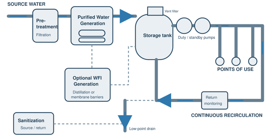
System Boundaries and Functional Segmentation
The water system should be divided into defined functional subsystems.
A typical arrangement includes:
- Source-water supply
- Pretreatment
- Primary purification
- Final purification or polishing
- Product-water storage
- Distribution
- Points of use
- Return monitoring
- Sanitization
- Waste, reject, and drain systems
- Automation and supporting utilities
System boundaries should be consistent across:
- User requirements
- Process-flow diagrams
- Piping and instrumentation diagrams
- Equipment specifications
- Control narratives
- Qualification protocols
- Sampling plans
- Maintenance procedures
- Change-control records
Undefined boundaries create practical problems. A pretreatment system may be treated as noncritical even though its operation directly affects membrane performance and product-water quality. A point-of-use hose may be excluded from the system even though it becomes the final delivery path to the manufacturing process.
Every component that can affect water quality, availability, or hygienic control should be included in the applicable engineering and lifecycle records.
Source-Water Characterization
Pharmaceutical-water generation normally begins with water meeting applicable drinking-water requirements. Potability establishes a starting point; it does not demonstrate that the source is consistent enough for a particular purification process.
The design assessment should consider:
- Municipal or private-source status
- Seasonal variation
- Multiple-source blending
- Hardness
- Alkalinity
- pH
- Conductivity
- Silica
- Iron and manganese
- Chlorine or chloramine
- Organic loading
- Turbidity
- Suspended solids
- Microbial quality
- Endotoxin, where relevant
- Temperature
- Pressure
- Flow availability
- Municipal treatment changes
- Supply interruptions
- Construction or flushing events
- Potential contaminants of local concern
Source-water requirements arise partly from 21 CFR 211.48 and the EPA National Primary Drinking Water Regulations in 40 CFR Part 141.
Historical source-water data should be used where available. A single sample taken during design is not adequate evidence of annual variability.
Where source water can be obtained from more than one municipal source, reservoir, or well, the design should address the worst relevant feed conditions. Changes in disinfectant, hardness, organic loading, or temperature can affect carbon beds, softeners, membranes, sanitization frequency, and microbial control.
Pretreatment Design
Pretreatment protects downstream purification equipment and helps establish a consistent feed-water condition.
Possible pretreatment stages include:
- Break tank or air-gap protection
- Booster pumping
- Coarse filtration
- Multimedia filtration
- Softening
- Antiscalant addition
- pH adjustment
- Activated carbon
- Sodium bisulfite addition
- Ultraviolet treatment
- Cartridge filtration
- Ultrafiltration
- Temperature adjustment
Not every system requires every stage. Pretreatment should be selected from the source-water characteristics and the requirements of the downstream technology.
Break Tanks and Air Gaps
Break tanks may provide:
- Hydraulic isolation
- Backflow protection
- Stable feed pressure
- Buffer volume
- Separation from an intermittent municipal supply
They can also create microbial risk if they are poorly covered, inadequately circulated, difficult to drain, or excluded from sanitization.
Softeners
Softeners reduce hardness and help protect reverse-osmosis membranes against scale. Their design should address:
- Duty and standby arrangements
- Regeneration sequence
- Brine preparation
- Resin sanitization
- Microbial growth
- Hardness breakthrough
- Channeling
- Regeneration-water quality
- Alarm and interlock requirements
Twin alternating units can support continuous operation, but the inactive unit must not become an uncontrolled stagnant volume.
Activated Carbon
Activated carbon is effective for removal of chlorine, chloramine, and some organic material. It can also support extensive microbial growth.
Design controls may include:
- Thermal or chemical sanitization
- Controlled backwashing
- Defined bed-contact time
- Differential-pressure monitoring
- Temperature monitoring
- Microbial monitoring
- Sampling before and after the bed
- Replacement criteria
Carbon beds should not be treated as passive filters.
Chemical Addition
Chemical dosing systems should address:
- Concentration control
- Low-level alarms
- Loss-of-dose detection
- Pump failure
- Incorrect chemical connection
- Backflow
- Mixing
- Overdosing
- Downstream removal
- Calibration
- Container identification
- Spill control
A chemical added to protect one process stage must not create an uncontrolled product-water impurity.
Purified Water Generation
Purified Water can be generated through an appropriate combination of technologies capable of meeting the USP official monograph Purified Water and the site’s additional chemical and microbial requirements.
Common technologies include:
- Reverse osmosis
- Electrodeionization
- Ion exchange
- Ultrafiltration
- Ultraviolet treatment
- Distillation
- Membrane degassing
- Final cartridge filtration
Reverse Osmosis
Reverse osmosis is commonly used as the principal removal barrier for:
- Dissolved ions
- Organic compounds
- Particulates
- Microorganisms
- Some endotoxins
Design considerations include:
- Single-pass versus double-pass arrangement
- Feed-water pressure and temperature
- Recovery rate
- Concentrate flow
- Membrane flux
- Scaling potential
- Chlorine tolerance
- Cleaning and sanitization
- Low-flow shutdown
- Permeate diversion
- Conductivity monitoring
- Startup flushing
- Membrane integrity
- Long shutdown management
A reverse-osmosis membrane should not be treated as an absolute microbial barrier. Organisms can enter downstream through poor connections, damaged membranes, stagnant piping, maintenance activities, or biofilm growth.
Electrodeionization
Electrodeionization is frequently installed downstream of reverse osmosis to provide continuing ionic removal without routine chemical regeneration.
The design should address:
- Feed-water conductivity
- Hardness and carbon-dioxide loading
- Flow and pressure
- Concentrate disposal
- Electrical power
- Startup and shutdown
- Sanitization compatibility
- Alarm response
- Resin or membrane fouling
Ultraviolet Treatment
Ultraviolet units may be used for:
- Microbial control
- Ozone destruction
- Reduction of organic compounds at appropriate wavelengths
The required function should be defined. A unit selected for microbial control is not automatically effective for total-organic-carbon reduction or ozone destruction.
Controls should address:
- Lamp intensity
- Lamp age
- Quartz-sleeve condition
- Flow rate
- Exposure
- Temperature
- Alarm setpoints
- Replacement intervals
Ultrafiltration
Ultrafiltration may be used to reduce microorganisms, particulates, and endotoxins. The design should address:
- Membrane configuration
- Integrity testing
- Retentate management
- Sanitization
- Differential pressure
- Fouling
- Recovery
- Startup and shutdown
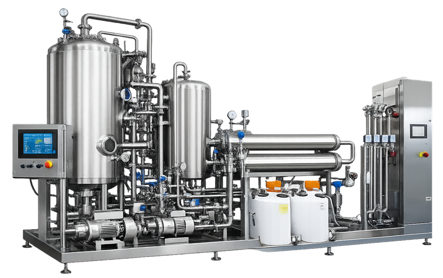
Water for Injection Generation
Water for Injection must meet the USP official monograph Water for Injection and the site’s requirements for chemical, microbial, and bacterial-endotoxin control.
WFI may be produced by distillation or by another purification process demonstrated to be equivalent or superior in removing chemicals and microorganisms.
Possible generation arrangements include:
- Multi-effect distillation
- Vapor-compression distillation
- Membrane-based generation using multiple purification barriers
- Combination systems incorporating reverse osmosis, electrodeionization, ultrafiltration, and other suitable controls
The selection should consider:
- Source-water quality
- Required production rate
- Feed-water pretreatment
- Endotoxin control
- Startup and shutdown behavior
- Sanitization
- Energy demand
- Cooling demand
- Reject or blowdown volume
- Maintenance capability
- Redundancy
- Instrumentation
- Applicable regulatory commitments
Distillation Systems
Distillation-system design should address:
- Feed-water quality
- Separator efficiency
- Entrainment control
- Steam quality
- Start-up diversion
- Conductivity monitoring
- Temperature and pressure
- Condensate removal
- Blowdown
- Venting
- Scaling
- Cleaning and descaling
- Low-demand operation
The first acceptable distillate should be diverted until defined operating conditions and water quality are achieved.
Membrane-Based WFI Systems
A membrane-based WFI system requires a coherent multiple-barrier strategy rather than reliance on a single component.
The strategy should address:
- Feed-water consistency
- Sequential removal barriers
- Membrane integrity
- Endotoxin reduction
- Microbial control
- Continuous or frequent sanitization
- Online monitoring
- Startup diversion
- Shutdown control
- Failure detection
- Preventive maintenance
- Recovery from adverse microbial trends
The design justification should establish how the full system consistently produces WFI—not merely that individual components possess adequate nominal removal ratings.
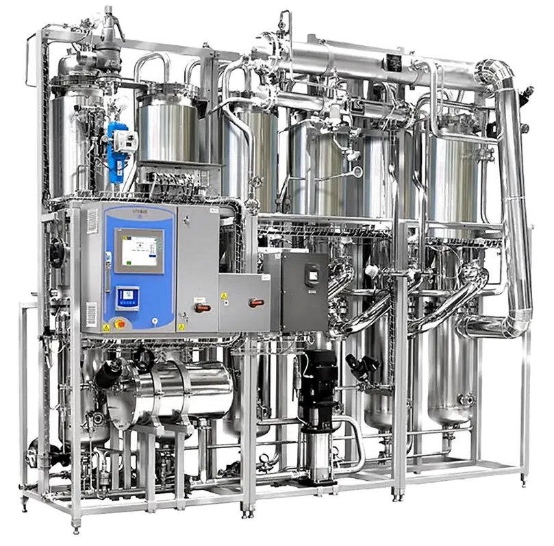
Product-Water Storage
A storage tank is an active element of the microbial- and chemical-control strategy.
Tank design should address:
- Required working volume
- Minimum operating volume
- Maximum fill volume
- Turnover
- Demand buffering
- Level control
- Overflow protection
- Venting
- spray coverage
- Drainability
- temperature control
- Recirculation
- Sanitization
- Sampling
- Internal inspection
- Maintenance access
Tank Sizing
Storage capacity should be based on:
- Normal daily demand
- Peak instantaneous demand
- Generation rate
- Generation-system recovery
- Planned sanitization
- Production schedule
- Laboratory demand
- Cleaning demand
- Required reserve
- Failure response
- Expected expansion
A large tank is not inherently safer. Excessive storage volume can increase water age and reduce turnover. An undersized tank can cause low-level trips, loss of distribution pressure, excessive generator cycling, or production interruption.
Tank Geometry and Drainability
A hygienic tank should minimize retained water and permit effective wetting during sanitization.
Design features may include:
- Sloped or dished bottom
- Low-point outlet
- Flush-mounted instruments
- Hygienic nozzles
- Minimal internal projections
- Spray device
- Suitable surface finish
- Drainable connections
- Controlled overflow arrangement
The tank outlet and return arrangement should support mixing and avoid poorly exchanged zones.
Vent Filters
A storage tank must exchange air as its level changes. The vent system should prevent the tank from becoming an uncontrolled contamination pathway.
Design considerations include:
- Hydrophobic vent-filter construction
- Microbial-retention rating
- Filter sizing
- Differential-pressure effects
- Heating, where required
- Condensation control
- Integrity testing
- Replacement interval
- Housing drainability
- Protection from external water
- Vacuum and overpressure protection
A blocked, wetted, undersized, or incorrectly installed vent filter can damage the tank or compromise microbial control.
Spray Devices
A spray device may support internal rinsing or sanitization, but its effectiveness depends on:
- Flow
- Pressure
- Coverage
- Spray pattern
- Tank geometry
- Obstructions
- Installation position
- Return and drain arrangement
Nominal installation of a spray ball does not demonstrate complete tank coverage.
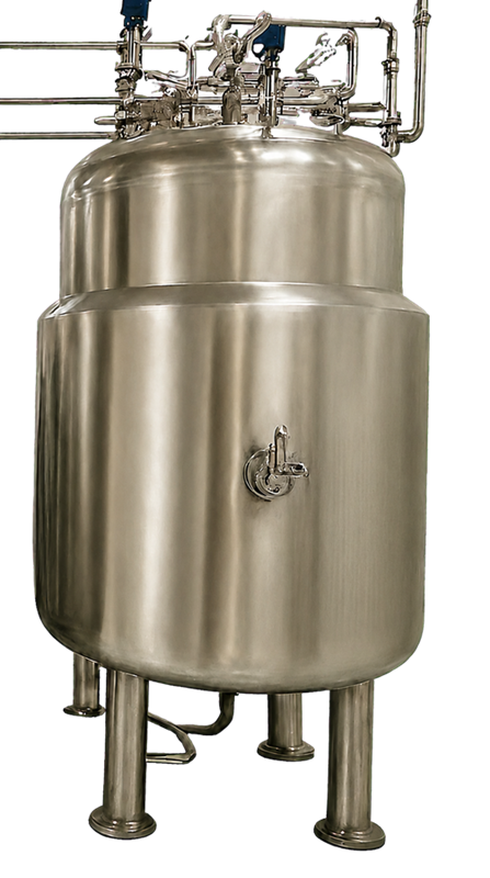
Distribution-System Architecture
The distribution system must preserve water quality from storage through every approved point of use and back to the defined system boundary.
A typical system uses a continuously recirculating loop. Alternative arrangements require documented technical justification and equivalent control of stagnation, microbial proliferation, sanitization, and point-of-use quality.
Distribution architecture may include:
- Single loop
- Multiple loops from a common tank
- Primary and secondary loops
- Dedicated manufacturing and laboratory loops
- Hot distribution
- Ambient distribution
- Hot storage with cooled points of use
- Ozonated ambient distribution
- Separate systems for different buildings or production areas
The architecture should be kept as simple as practical. Each additional branch, subloop, cooler, valve, hose, and user increases the number of locations that must be controlled, sanitized, maintained, sampled, and qualified.
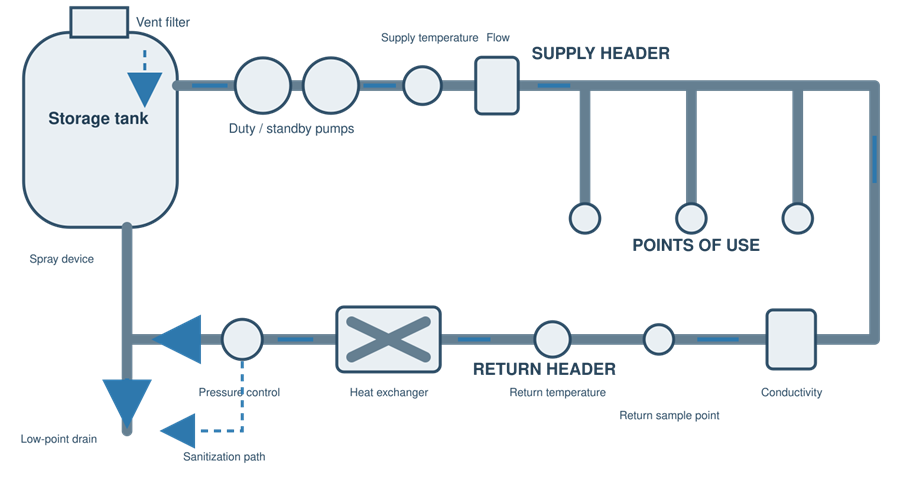
Storage tank, duty and standby circulation pumps, supply header, representative user branches, return header, heat exchanger where applicable, supply and return temperature, flow and conductivity instruments, return sampling point, pressure control, sanitization path, and low-point drain.
Distribution Hydraulics
Hydraulic design should demonstrate adequate performance across the complete operating range.
The analysis should include:
- Normal production
- Maximum simultaneous demand
- Minimum demand
- No-user demand
- Tank filling
- Low tank level
- Filter loading
- Pump changeover
- Heat-exchanger operation
- Sanitization
- System expansion
- Failure conditions
Flow and Velocity
Adequate flow helps reduce stagnation and supports heat transfer, mixing, and sanitization. However, a universal velocity value should not be presented as a regulatory requirement or a substitute for engineering assessment.
Required flow depends on:
- Pipe diameter
- Loop configuration
- Surface condition
- Temperature
- Sanitization method
- Demand
- Pump capability
- Pressure requirements
- Point-of-use operation
- System history
The design should establish justified operating ranges rather than relying on a single velocity slogan.
Pressure
Pressure should be adequate at the most hydraulically disadvantaged point under peak demand.
The design should address:
- Minimum point-of-use pressure
- Maximum allowable pressure
- Pump head
- Elevation changes
- Simultaneous users
- Control-valve losses
- Filter and heat-exchanger losses
- Return pressure
- Pump minimum-flow requirements
- Water hammer
- Pressure-relief arrangements
Pressure-control methods should not create stagnant bypasses or uncontrolled low-flow conditions.
Pump Selection
Distribution pumps should be sized for the complete operating envelope.
Design considerations include:
- Hygienic construction
- Drainability
- Seal design
- Cavitation prevention
- Net positive suction head
- Minimum-flow protection
- Variable-speed control
- Heat input
- Duty and standby configuration
- Changeover
- Maintenance isolation
- Sanitization
- Alarm and trip logic
A standby pump can become a dead leg if it is isolated and retains water. The design should provide hygienic circulation, periodic changeover, drainability, or another justified control.
Hydraulic Balancing
Where one storage system supplies multiple loops, balancing should prevent one circuit from taking flow needed by another.
Balancing arrangements should be:
- Hygienic
- Accessible
- Documented
- Stable across demand conditions
- Included in commissioning and qualification
Materials of Construction
Product-water contact materials must be compatible with:
- Required water quality
- Operating temperature
- Sanitization temperature
- Sanitization chemicals
- Ozone
- Cleaning chemicals
- Pressure
- Flow
- Expected service life
Common materials include:
- Austenitic stainless steel
- Qualified thermoplastic piping
- Elastomers
- Sanitary glass or specialty materials for limited applications
Material selection must be justified for the specific system.
Stainless Steel
Stainless-steel design considerations include:
- Alloy
- Product-contact surface finish
- Weld quality
- Passivation
- Rouge management
- Corrosion risk
- Drainability
- Heat-affected zones
- Elastomer compatibility
- Sanitization conditions
A specified surface-roughness value does not compensate for poor welds, retained water, damaged passivation, or improper maintenance.
Polymeric Systems
Qualified polymeric systems may be appropriate for some Purified Water or WFI applications.
The assessment should address:
- Temperature rating
- Pressure rating
- Sanitization compatibility
- Leachables
- Permeability
- Jointing method
- Mechanical support
- Ultraviolet exposure
- Inspection capability
- Repair methods
- Service life
- Regulatory and site requirements
Elastomers
Gaskets, diaphragms, O-rings, and seals should be controlled by:
- Material specification
- Compatibility assessment
- Installation requirements
- Traceability where required
- Inspection
- Replacement interval
- Storage conditions
- Change control
Elastomer failure can create particles, leakage, microbial harborage, or loss of valve function.
Hygienic Piping and Welds
Hygienic construction should minimize retention, crevices, rough surfaces, contamination entry, and locations that cannot be sanitized.
Design and fabrication controls may include:
- Orbital welding
- Approved manual-weld procedures where necessary
- Weld identification
- Weld maps
- Borescope inspection
- Acceptance criteria
- Purging controls
- Fitting alignment
- Passivation
- Slope verification
- Material certificates
- Surface-finish records
- Controlled field modifications
Weld records should be connected to the installed location. A collection of acceptable weld coupons does not prove that each installed weld is acceptable.
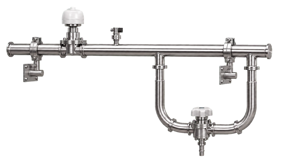
Installed stainless-steel distribution piping showing orbital welds, hygienic supports, diaphragm valves, instrument connections, and a representative point-of-use branch.
Dead Legs, Branches, Slope, and Drainability
Dead Legs
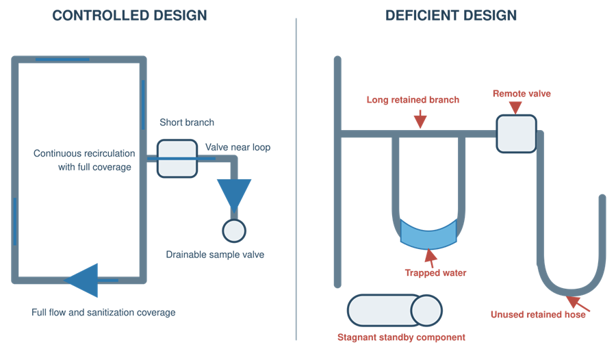
A dead leg is a location in which water exchange is inadequate relative to the main flow path. It may support stagnation, microbial growth, residue accumulation, or incomplete sanitization.
Dead-leg assessment should consider:
- Branch length
- Branch diameter
- Valve location
- Valve orientation
- Frequency of use
- Flow during normal operation
- Flow during sanitization
- Temperature
- Drainability
- Sampling results
- Maintenance requirements
A geometric ratio can be a useful design criterion, but it should not be treated as proof that a branch is hygienically acceptable. A short branch may still retain water because of orientation or valve design. A longer branch may receive effective flow through a properly engineered arrangement.
Point-of-Use Branches
Point-of-use branches should be:
- As short as practical
- Positioned to minimize retained water
- Included in sanitization
- Accessible for operation and maintenance
- Drainable where required
- Protected from backflow
- Designed for representative sampling
Frequently unused branches should not remain installed without a defined control strategy.
Slope
Where drainability is required, piping should be installed to a defined slope toward controlled low points.
The design should address:
- Direction of slope
- Structural deflection
- Pipe supports
- Thermal expansion
- Equipment connections
- Valve orientation
- Local low points
- Field-routing changes
- Verification method
A slope shown on a drawing is not evidence that the installed system drains.
Drains
Drains should be designed to prevent:
- Backflow
- Aerosol transfer
- Direct cross-connection
- Standing water
- Uncontrolled discharge
- Operator exposure
- Thermal or chemical hazard
Drain systems should not create a contamination path into the pharmaceutical-water system.
Heat Exchangers and Temperature Control
Heat exchangers may be used to:
- Heat the loop
- Cool the loop
- Support thermal sanitization
- Provide tempered water at selected users
- Remove pump heat
- Destroy ozone indirectly through a controlled thermal process
Design risks include:
- Leakage between utility and product-water sides
- Poor drainability
- Retained water
- Fouling
- Inadequate sanitization
- Cross-contamination
- Uncontrolled cold zones
- Condensation
- Excessive residence time
Where a lower-quality utility could contaminate product water through a heat-exchanger failure, the design should consider:
- Double-tube-sheet or double-wall construction
- Pressure differential
- Leak detection
- Intermediate monitoring
- Preventive maintenance
- Inspection
- Appropriate alarm response
Point-of-Use Coolers
A point-of-use cooler can create a localized microbial risk when water remains cold and stagnant between uses.
Controls may include:
- Return-to-loop circulation
- Automatic hot-water flush
- Periodic sanitization
- Drainability
- Controlled use frequency
- Temperature monitoring
- Defined pre-use flushing
- Sampling
- Removal of unused coolers
Sanitization as a Design Function
Sanitization must be established during design. It cannot be added effectively after the system has been built if components, materials, branches, or flow paths are incompatible.
Possible strategies include:
- Continuous hot operation
- Periodic hot-water sanitization
- Steam sanitization of suitable components
- Ozone sanitization
- Chemical sanitization
- Ultraviolet support
- Combined approaches
The selected method should provide controlled exposure throughout the required system boundary.
Thermal Sanitization
The design should define:
- Sanitization temperature
- Exposure duration
- Monitoring locations
- Heat-up time
- Cold-point location
- Return temperature
- Pump operation
- Valve sequencing
- User-branch coverage
- Tank spray coverage
- Cooldown
- Operator protection
- Release to use
A heater outlet temperature alone does not demonstrate that the complete system received the required thermal exposure.
Ozone Sanitization
Ozonated systems should address:
- Ozone generation
- Gas concentration
- Water concentration
- Distribution
- Tank headspace
- Return concentration
- Contact time
- Destruction before use
- Ultraviolet intensity
- Off-gas destruction
- Personnel safety
- Materials compatibility
- Alarm response
The system must prevent ozonated water from being released to a process where ozone would create product, equipment, or personnel risk.
Chemical Sanitization
Chemical sanitization requires controls for:
- Chemical identity
- Concentration
- Distribution
- Contact time
- Temperature
- Materials compatibility
- Branch coverage
- Rinsing
- Residual testing
- Drain disposal
- Personnel protection
- Release to service
Sanitization Coverage
The design review should verify coverage of:
- Generation equipment
- Membrane housings
- Storage tanks
- Tank vents where applicable
- Pumps
- Heat exchangers
- Supply and return piping
- Standby equipment
- Instrument connections
- Sample valves
- Points of use
- Normally closed branches
Points of Use
The point of use is where the controlled utility interfaces with manufacturing, cleaning, laboratory, or another user system.
Design considerations include:
- Required flow and pressure
- Water temperature
- Valve type
- Branch geometry
- Drainability
- Backflow prevention
- Hose connection
- Sampling
- Flushing
- Sanitization
- Access
- Labeling
- Protection from misuse
- Cross-connection control
Hoses
Where hoses are necessary, controls should address:
- Hygienic construction
- Length
- Storage
- Drainage
- Drying
- Cleaning
- Sanitization
- Inspection
- Identification
- Replacement
- Connection protection
- Dedicated versus shared use
An uncontrolled hose can negate the hygienic design of the fixed distribution system.
Direct Connections
Hard-piped connections reduce some hose-related risks but can create others, including:
- Backflow from the user system
- Product ingress
- Cleaning-agent ingress
- Pressure transfer
- Incomplete sanitization
- Undefined ownership at the interface
The interface should have an identified boundary, approved operating sequence, and defined response to abnormal conditions.
Sampling-Point Design
Sampling points should permit representative samples without creating a contamination source.
The design should consider:
- Location
- Valve type
- Branch length
- Orientation
- Drainability
- Sanitization
- Flush requirements
- Operator access
- Sample-container clearance
- Splash control
- Labeling
- Temperature safety
- Connection to the actual point of use
A sample valve located near a point of use may not represent the water delivered through a separate hose, cooler, filter, or user connection.
Sampling locations should include, as justified:
- Source water
- After important pretreatment stages
- After primary purification
- Generator outlet
- Storage tank
- Distribution supply
- Distribution return
- Representative points of use
- Hydraulically remote points
- High-risk or low-use points
- Points following local cooling or treatment
The system drawing should identify every routine and qualification sampling location.
Online Monitoring and Instrumentation
Instrumentation should support control of the process and timely detection of adverse conditions.
Possible measurements include:
- Conductivity or resistivity
- Total organic carbon
- Temperature
- Flow
- Pressure
- Tank level
- Ozone
- Ultraviolet intensity
- Chlorine
- Hardness
- pH
- Differential pressure
- Pump status
- Valve position
Instrumentation should be located where the result is meaningful. A high-quality reading at the generator cannot detect contamination introduced or developed in the distribution loop.
Return Monitoring
Return-line measurements can provide evidence of the water condition after it has traveled through the loop. Depending on the system, return monitoring may include:
- Conductivity
- Total organic carbon
- Temperature
- Flow
- Ozone
- Pressure
Return monitoring does not replace point-of-use sampling, but it can detect system-level deterioration and loss of critical operating conditions.
Instrument Design
Instrumentation design should address:
- Measurement range
- Accuracy
- Resolution
- Response time
- Temperature compensation
- Sanitary connection
- Drainability
- Calibration
- Removal and replacement
- Redundancy
- Failure mode
- Alarm generation
- Data retention
Automation, Alarms, and Data Integrity
Automated control should be based on an approved control philosophy and detailed functional requirements.
Controlled functions may include:
- Generator startup and shutdown
- Tank-level control
- Product-water diversion
- Pump sequencing
- Duty and standby changeover
- Valve sequencing
- Sanitization
- Heating and cooling
- Ozone generation and destruction
- Chemical dosing
- Alarm management
- Interlocks
- Data acquisition
- Trending
- User access
- Recipe or setpoint management
Computerized-system lifecycle expectations are addressed in Qualification and Verification of Facility Automation Systems.
Alarms
Alarm design should identify:
- Condition detected
- Setpoint
- Delay
- Priority
- Operator response
- Automatic system action
- Escalation
- Acknowledgment
- Recording
- Return-to-normal behavior
- Quality impact
Possible alarm conditions include:
- High product-water conductivity
- High total organic carbon
- Low distribution flow
- Low return temperature
- Low tank level
- High tank level
- Pump failure
- Loss of ozone destruction
- Ultraviolet failure
- Chemical-dosing failure
- High filter differential pressure
- Loss of compressed air
- Instrument failure
- Communication failure
Interlocks and Diversion
Where a critical condition can produce unacceptable water, the system should define whether it will:
- Divert water
- Stop generation
- Prevent transfer to storage
- Close affected points of use
- Maintain circulation
- Initiate standby equipment
- Require quality-unit assessment
- Place the system in a restricted state
The design should prevent repeated automatic restarting from concealing an unresolved failure.
Data Integrity
Electronic records used to demonstrate water-system control should be assessed for:
- Accurate time stamps
- User access
- Audit trails
- Setpoint changes
- Alarm history
- Data retention
- Backup and recovery
- Interface reliability
- System clocks
- Review capability
- Protection against unauthorized changes
- Identification of missing data
A 21 CFR Part 11 assessment should determine whether applicable electronic records and electronic signatures fall within Part 11 scope.
Capacity and Demand Management
The system should consistently support the approved demand profile without loss of quality, pressure, flow, or sanitization capability.
Capacity calculations should address:
- Average hourly demand
- Average daily demand
- Maximum daily demand
- Peak instantaneous demand
- Simultaneous users
- Cleaning cycles
- Batch preparation
- Laboratory consumption
- Sanitization consumption
- Generator production rate
- Tank working volume
- Minimum reserve
- Recovery time
- Expected expansion
The analysis should distinguish between:
- Generation capacity
- Storage capacity
- Distribution capacity
- Point-of-use capacity
A large storage tank does not correct inadequate distribution flow. A large pump does not correct inadequate generation capacity.
Minimum Demand
Low demand can be as important as peak demand. The design should assess:
- Excessive storage time
- Low tank turnover
- Low generator operating frequency
- Membrane stagnation
- Pump minimum-flow requirements
- Temperature drift
- Ozone exposure
- Reduced point-of-use flushing
Future Capacity
Expansion allowances should be controlled. Unused capped branches installed for possible future users can become dead legs. Future connections should be designed so they do not compromise the current system before activation.
Redundancy and Failure Management
Redundancy should be based on business continuity, product risk, required availability, repair time, and the consequence of failure.
Possible redundant components include:
- Feed pumps
- Softeners
- Reverse-osmosis trains
- Distribution pumps
- Heaters
- Ultraviolet units
- Ozone generators
- Critical instruments
- Automation hardware
- Power supplies
Redundancy creates its own risks:
- Stagnant standby equipment
- Unverified automatic changeover
- Inconsistent maintenance
- Unequal operating hours
- Hidden failure of the standby unit
- Complex valve arrangements
- Incomplete sanitization
The design should establish:
- Duty and standby operating philosophy
- Changeover frequency
- Automatic or manual transfer
- Permitted degraded modes
- Alarm response
- Testing of standby functions
- Drainability
- Sanitization
- Return-to-service requirements
A redundant component that cannot be demonstrated to operate when required does not provide effective redundancy.
Utilities and Supporting Systems
Water-system performance may depend on:
- Electrical power
- Plant steam
- Clean steam
- Chilled water
- Hot water
- Compressed air
- Instrument air
- Drainage
- Ventilation
- Building automation
- Process automation
- Network communication
The design should identify the effect of failure or variation in each supporting utility.
For example:
- Loss of compressed air may place control valves in unsafe positions.
- Loss of power may stop circulation.
- Loss of cooling may raise distribution temperature.
- Loss of steam may prevent sanitization.
- Restricted drainage may prevent complete emptying.
- Network failure may interrupt data collection without stopping the physical system.
Required fail positions and recovery actions should be defined.
Maintainability and Access
A hygienic system must also be maintainable.
The design should provide safe access for:
- Instrument calibration
- Filter replacement
- Vent-filter testing
- Pump maintenance
- Membrane replacement
- Ultraviolet lamp replacement
- Valve-diaphragm replacement
- Heat-exchanger inspection
- Passivation
- Sampling
- Tank inspection
- Welding repair
- Drainage
- Sanitization
- Lockout and tagout
Poor access increases the likelihood of:
- Improvised maintenance
- Contamination entry
- Incorrect reassembly
- Extended downtime
- Incomplete inspection
- Unsafe work
- Uncontrolled temporary connections
Maintenance isolation should not create stagnant volumes that remain connected to the operating loop.
Commissioning and Qualification Design Provisions
Design should make the system testable.
Provisions should support verification of:
- Equipment identification
- Materials
- Welds
- Surface finish
- Passivation
- Slope
- Drainability
- Tank spray coverage
- Vent-filter integrity
- Instrument calibration
- Alarm functions
- Interlocks
- Pump changeover
- Flow and pressure
- Heating and cooling
- Sanitization coverage
- Point-of-use operation
- Sampling
- Startup diversion
- Failure response
- Backup and recovery
- Maximum demand
- Minimum demand
Qualification follows the broader GMP Validation Life Cycle and the water-system-specific framework in Pharmaceutical Water System Qualification and Performance Verification.
Commissioning data may be used during qualification when:
- Requirements are approved.
- Test methods are suitable.
- Instruments are calibrated.
- Execution is controlled.
- Deviations are documented.
- Results are traceable.
- Records are reviewed and accepted.
- The evidence satisfies the approved qualification strategy.
Commissioning should not be repeated merely because it was performed by an engineering organization. It also should not be accepted without assessment simply because the result appears technically acceptable.
Design Documentation
The design package should provide sufficient evidence to understand, build, operate, maintain, qualify, and change the system.
Typical documents include:
- User requirements specification
- Design basis
- Intended-use matrix
- Source-water assessment
- Capacity and demand calculations
- Process-flow diagrams
- Piping and instrumentation diagrams
- Equipment specifications
- Instrument index
- Valve list
- Line list
- Sampling-point list
- Materials specifications
- Surface-finish requirements
- Weld specifications
- Control philosophy
- Functional specification
- Alarm and interlock matrix
- Cause-and-effect matrix
- Sanitization strategy
- Automation architecture
- Data-flow diagram
- Part 11 assessment
- Failure-mode assessment
- Maintenance strategy
- Spare-parts strategy
- Commissioning plan
- Qualification strategy
- Requirements traceability matrix
Design changes should be reflected in the final as-built records. A system should not be released with substantial unresolved differences between drawings, automation configuration, field installation, and qualification documentation.
Design Review and Risk Assessment
Design review should be multidisciplinary.
Participants may include:
- Engineering
- Manufacturing
- Quality
- Validation
- Microbiology
- Laboratory
- Maintenance
- Metrology
- Automation
- Information technology
- Environmental health and safety
- System supplier
The review should evaluate:
- Intended-use coverage
- Source-water risks
- Removal barriers
- Microbial-control strategy
- Endotoxin control
- Sanitization coverage
- Hydraulic performance
- Material compatibility
- Dead legs
- Drainability
- Sampling
- Monitoring
- Automation
- Data integrity
- Capacity
- Redundancy
- Failure recovery
- Maintainability
- Qualification capability
- Future expansion
The Risk-Based Approach to Validation should be used to determine where additional design control, testing, monitoring, or redundancy is justified.
Risk assessment does not make a poor hygienic design acceptable. Its purpose is to identify and control risk before installation and release.
Common Design Deficiencies
Requirements and Capacity
- Intended uses are incomplete.
- Peak simultaneous demand is not calculated.
- The system is sized only from average daily use.
- Future demand is assumed without a controlled expansion plan.
- The tank is oversized and has inadequate turnover.
- Low-demand operation is not assessed.
- Required availability is not defined.
Pretreatment and Generation
- Source-water variability is not characterized.
- Chloramine removal is not addressed.
- Carbon beds lack microbial controls.
- Standby pretreatment units retain stagnant water.
- Chemical dosing has no loss-of-dose detection.
- Startup water is not diverted.
- Membrane shutdown and restart are uncontrolled.
- A single membrane is treated as an absolute microbial barrier.
Storage and Distribution
- Tank venting is inadequately designed.
- Spray-device coverage is assumed.
- The tank or loop cannot drain.
- Pump sizing does not cover peak demand.
- Standby pumps are stagnant.
- Hydraulic balancing is absent.
- Return conditions are not monitored.
- Branches are retained for users that no longer exist.
- Local coolers create stagnant cold sections.
- Flow criteria are copied without engineering justification.
Hygienic Construction
- Field welds are not traceable.
- Borescope inspection is incomplete.
- Piping slope exists only on drawings.
- Valve orientation retains water.
- Elastomers are not standardized.
- Surface-finish requirements are inconsistent.
- Maintenance isolation creates dead legs.
- Uncontrolled hoses form the final delivery path.
Sanitization
- The sanitization method is selected after construction.
- Materials are incompatible with sanitization conditions.
- Cold points are not identified.
- Branches and standby equipment are not included.
- Sanitization parameters are monitored only at the heater outlet.
- Chemical residues are not assessed before release.
- Ozone destruction lacks an interlock.
- Sanitization cannot be performed during required production schedules.
Sampling and Monitoring
- Sampling points do not represent actual points of use.
- Sample valves are long, uncirculated branches.
- Return monitoring is omitted.
- Instruments are inaccessible for calibration.
- Alarm delays mask adverse conditions.
- Instrument failure is not distinguished from an acceptable reading.
- Missing electronic data are not detected.
Automation and Failure Response
- Control logic is not described in approved documentation.
- Setpoints and delays are not justified.
- Alarm response is undefined.
- Automatic restart conceals recurring failures.
- Standby changeover is not tested.
- Data retention and backup are not defined.
- Supporting-utility failures are not evaluated.
- Manual operation bypasses normal safeguards.
Regulatory and Technical Framework
The principal United States regulatory and technical references include:
- 21 CFR Part 211
- 21 CFR 211.48
- 21 CFR 211.63
- 21 CFR 211.65
- 21 CFR 211.67
- 21 CFR 211.68
- 21 CFR Part 11
- 40 CFR Part 141
- USP official monograph Purified Water
- USP official monograph Water for Injection
- USP General Chapter 〈1231〉 Water for Pharmaceutical Purposes
- USP General Chapter 〈643〉 Total Organic Carbon
- USP General Chapter 〈645〉 Water Conductivity
- USP General Chapter 〈85〉 Bacterial Endotoxins Test, where applicable
- FDA’s Sterile Drug Products Produced by Aseptic Processing—Current Good Manufacturing Practice
- FDA’s Guide to Inspections of High Purity Water Systems
The 1993 FDA high-purity-water inspection guide contains useful historical observations concerning water-system design, microbial control, drawings, sampling, and distribution. FDA identifies it as nonbinding reference material for investigators. It should not be presented as a current regulation, a current compendial standard, or the sole basis for modern water-system design.
Applicable regulations, official monographs, approved regulatory applications, product requirements, current technical standards, and the site’s documented risk assessment remain controlling.
Summary
A pharmaceutical water system must control the complete path from source water to the point of use. Effective design requires:
- Requirements based on actual intended uses
- Characterization of source-water variability
- Pretreatment matched to downstream technologies
- Multiple appropriate purification and control barriers
- Hygienic storage and venting
- Controlled distribution hydraulics
- Compatible materials and qualified fabrication
- Minimal stagnation and retained water
- Sanitization coverage through the complete system
- Representative sampling
- Meaningful online monitoring
- Defined alarms, interlocks, and failure responses
- Capacity for both peak- and minimum-demand conditions
- Redundancy that does not create stagnant equipment
- Maintenance and calibration access
- Testable design requirements
- Accurate as-built documentation
- Lifecycle control after release
The governing sequence is:
Intended use → source-water assessment → process design → storage and distribution design → contamination controls → automation and monitoring → commissioning → qualification → release → lifecycle control