

Depyrogenation Equipment and Process Design
Depyrogenation equipment is used to remove or inactivate pyrogenic contamination, particularly bacterial endotoxin, on pharmaceutical containers, components, tools, and product-contact equipment. For heat-resistant materials, high-temperature dry heat is the principal destructive method.
A depyrogenation process is not defined by temperature alone. Its effectiveness depends on the combined control of:
- Temperature
- Exposure time
- Airflow and heat transfer
- Component characteristics
- Load density and arrangement
- Conveyor speed for continuous tunnels
- Heating-zone dimensions
- Cooling conditions
- Equipment controls and alarms
- Protection after processing
The equipment must deliver a reproducible process capable of achieving the required endotoxin reduction while preventing component damage and post-process recontamination. The design should support the broader endotoxin control strategy rather than function as an isolated processing step.
Depyrogenation and Sterilization Are Related but Different
Sterilization destroys viable microorganisms. Depyrogenation removes or inactivates pyrogenic material. Bacterial endotoxin may remain after the microorganisms that produced it have been killed.
High-temperature dry heat applied to glass components generally provides substantial microbial lethality while also destroying endotoxin. However, equipment design and process qualification must be based on the intended performance claim.
A depyrogenation claim requires evidence of endotoxin reduction. Temperature exposure or biological-indicator lethality alone does not establish that claim. The relationship among viable organisms, endotoxin, sterilization, and depyrogenation is explained in Pyrogens and Bacterial Endotoxins in GMP Manufacturing.
Equipment Design Basis
The design basis should identify:
- Components and materials to be processed
- Container sizes, shapes, masses, and configurations
- Required throughput
- Maximum and minimum load conditions
- Required endotoxin reduction
- Sterility requirements, where applicable
- Maximum acceptable thermal exposure
- Upstream washing and handling conditions
- Downstream filling or assembly interface
- Required environmental classification
- Available utilities
- Automation and data-recording requirements
- Cleaning and maintenance strategy
- Qualification and requalification requirements
The design must accommodate both minimum-process and maximum-process conditions. Insufficient thermal exposure can result in inadequate endotoxin reduction. Excessive exposure can cause glass distortion, cosmetic defects, increased breakage, lubricant degradation, particulate generation, or damage to other heat-sensitive materials.
One universal temperature, exposure time, belt speed, or loading limit cannot be applied to every depyrogenation system. These limits must be developed for the specific equipment, component, and process.
Principal Equipment Configurations
Batch Dry-Heat Ovens
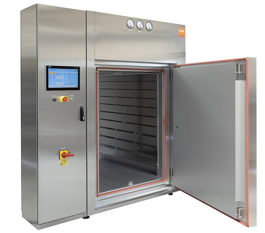
Batch ovens process components on shelves, trays, racks, or carts within an enclosed chamber. Heated air is circulated through the chamber for a defined cycle that normally includes heating, exposure, and cooling phases.
Batch ovens are commonly used for:
- Glassware
- Stainless-steel tools
- Product-contact parts
- Filling-machine components
- Laboratory equipment
- Other heat-resistant assemblies
Their principal engineering challenge is achieving reproducible heat distribution and heat penetration across different load masses, shelf positions, and component configurations.
Continuous Depyrogenation Tunnels
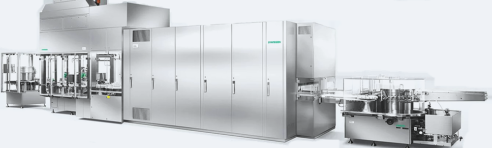
Continuous tunnels transport containers through sequential processing zones on a conveyor. They are commonly integrated between a container washer and an aseptic filling machine.
Typical applications include:
- Glass vials
- Ampoules
- Cartridges
- Other heat-resistant containers suitable for continuous processing
The principal engineering challenge is coordinating airflow, zone temperature, pressure relationships, conveyor speed, container density, cooling, and upstream/downstream equipment operation.
Multipurpose Dry-Heat Chambers
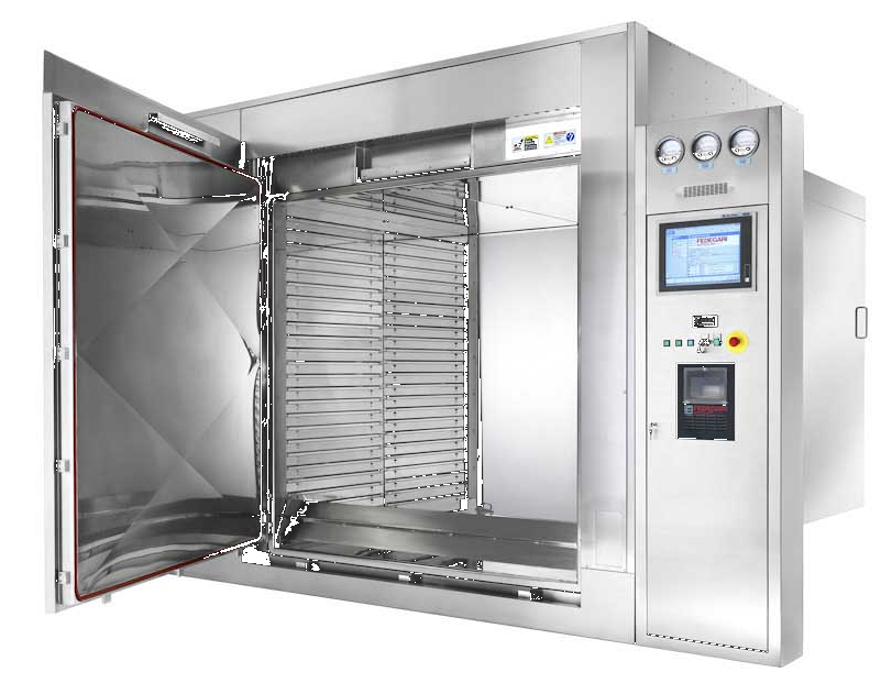
Some batch chambers support both sterilization and depyrogenation cycles. The same chamber may use different recipes, temperature ranges, exposure periods, loading patterns, and performance criteria depending on the intended process.
This flexibility does not create one combined validation claim. Sterilization performance and endotoxin-reduction performance must be established using criteria appropriate to each process.
Equipment Comparison
| Design feature | Batch oven | Continuous tunnel | Multipurpose chamber |
|---|---|---|---|
| Operating mode | Defined batch cycle | Continuous processing | Defined batch cycle |
| Material movement | Stationary load | Conveyor transport | Stationary load |
| Primary time control | Exposure timer and cycle logic | Conveyor speed and heated-zone length | Recipe and exposure timer |
| Main heat-transfer variables | Air circulation, load mass and arrangement | Zone airflow, container density and belt speed | Air circulation and load configuration |
| Cooling | In-chamber or controlled unloading | Dedicated cooling zone | In-chamber or controlled unloading |
| Manufacturing integration | Separate processing step | Washer-to-filler integration | Separate processing step |
| Principal design risk | Load-dependent cold locations | Zone, conveyor and airflow interaction | Incorrect recipe or load selection |
| Post-process protection | Closed chamber, controlled unloading and storage | Protected cooling and direct transfer | Closed chamber, controlled unloading and storage |
Batch-Oven Architecture
A batch oven may include:
- Insulated chamber
- One or two access doors
- Shelves, carts, trays, or racks
- Electric or other suitable heating system
- Recirculation fans
- Supply and return-air paths
- HEPA-filtered air, where required
- Exhaust or bleed-air control
- Temperature-control sensors
- Independent monitoring sensors
- Door seals and interlocks
- PLC or other cycle controller
- Data recorder or historian
- Cooling system
- Pressure monitoring
- Alarm and safety systems
Pass-through ovens can establish a physical boundary between the loading area and the controlled unloading area. Door interlocks should prevent simultaneous opening where such opening could compromise segregation or the protected status of the load.
Airflow Through the Load
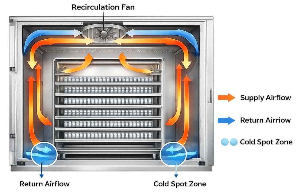
Air should circulate across and through the usable load volume without being excessively obstructed by shelves, trays, racks, or densely arranged components.
Poor airflow distribution can produce:
- Localized cold areas
- Slow heat penetration
- Excessive chamber temperature gradients
- Extended cycle duration
- Uneven cooling
- Hot locations that damage components
The loading configuration must therefore be treated as part of the process, not merely as an operating convenience.
Oven Loading
Defined loading patterns should address:
- Component identity
- Quantity and load mass
- Shelf or rack positions
- Component orientation
- Spacing between items
- Openings that must remain exposed to airflow
- Maximum tray loading
- Minimum and maximum loads
- Mixed-load restrictions
- Heat-sensitive items
- Required load diagrams
The maximum load is not automatically the only thermal worst case. A dense load may challenge heat penetration, while a small or partial load may alter airflow distribution or create higher component temperatures. Qualification must identify the relevant worst cases.
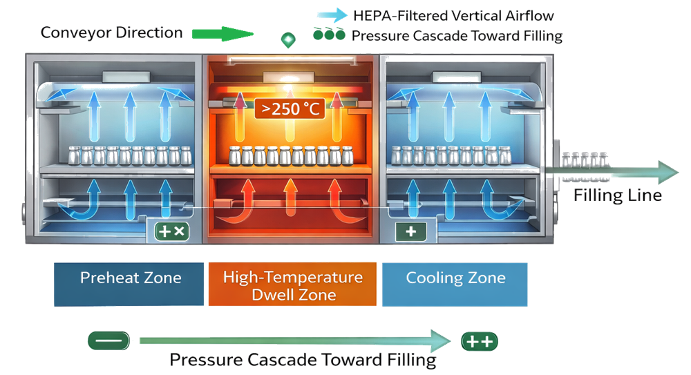
Three-Zone Depyrogenation Tunnel
A continuous tunnel commonly includes three functional sections:
- Infeed or preheating zone
- High-temperature depyrogenation zone
- Controlled cooling zone
The exact boundaries, airflow arrangements, filters, and pressure relationships depend on the equipment design.
Infeed and Preheating Zone
Washed containers enter the tunnel from the washer or transfer conveyor. This zone prepares them for the high-temperature section by removing residual moisture and initiating controlled heating.
Design considerations include:
- Washer-to-tunnel transfer
- Residual rinse water
- Container spacing
- Container stability
- Infeed accumulation
- Airflow direction
- Migration of heat toward the washer
- Protection against environmental contamination
- Detection of tipped, broken, or jammed containers
Residual water can increase heating variability and may produce container damage if the transition to high temperature is too abrupt. The washer, transfer path, and tunnel should therefore be evaluated as an integrated process.
High-Temperature Zone
The high-temperature zone delivers the thermal exposure required for endotoxin destruction.
Important design elements include:
- Effective heated length
- Heating capacity
- Temperature setpoints and operating ranges
- Airflow distribution
- Air velocity
- Conveyor speed
- Container density
- Lateral position across the belt
- Zone-boundary stability
- Temperature recovery after interruptions
- Hot and cold locations
- Maximum component exposure
The process must provide acceptable exposure across the full qualified conveyor width. Centerline performance alone does not establish uniform exposure at belt edges or near zone transitions.
Cooling Zone
Containers leaving the high-temperature zone must be cooled to a condition suitable for filling or further handling without losing their sterile and depyrogenated status.
Cooling-zone design should address:
- HEPA-filtered air supply
- Airflow pattern over exposed containers
- Cooling capacity at maximum throughput
- Zone temperature
- Container exit temperature
- Pressure relationships
- Filter integrity
- Protection during conveyor stoppage
- Interface with the filling machine
- Exposure time before filling
- Recovery after access or maintenance
Where open sterile containers exit directly into an aseptic filling area, the cooling and transfer path should provide environmental protection consistent with the aseptic-processing design, typically including unidirectional HEPA-filtered airflow at the exposed-container location.
Conveyor Speed and Residence Time
Conveyor speed controls the time available for heating, depyrogenation, and cooling. For a defined effective zone length: t=vL , where:
- t = residence time in the applicable zone
- L = effective zone length
- v = conveyor speed
The effective length must reflect the portion of the tunnel that actually provides the defined process conditions. It should not automatically be assumed to equal the physical enclosure length.
Increasing belt speed decreases residence time and normally challenges minimum thermal exposure. Decreasing belt speed increases exposure and may challenge maximum container temperature, cooling capacity, glass quality, or downstream line coordination.
The design should provide:
- Defined speed range
- Calibrated or verified speed measurement
- Continuous speed indication
- Recipe-specific speed control
- High- and low-speed alarms
- Detection of belt stoppage
- Interlocks preventing processing outside the approved range
- Controlled response to upstream and downstream line stops
- Recording of actual speed during processing
Tunnel Airflow and HEPA Filtration
Tunnel airflow transfers heat, supports temperature uniformity, separates processing zones, and protects cooled containers. Design considerations include:
- Supply-air location
- Return-air location
- Recirculated and make-up air
- Airflow direction through each zone
- Air velocity
- Filter location
- Filter temperature rating
- Filter-housing expansion
- Seal compatibility
- Differential-pressure monitoring
- Zone-to-zone air migration
- Exhaust and bleed-air control
- Access for integrity testing and replacement
Vertical unidirectional airflow is commonly used over exposed containers, particularly in the cooling and protected transfer areas. The airflow arrangement in every zone should nevertheless be described from the actual equipment design rather than labeled universally as “laminar.”
High-temperature operation can subject filters, seals, frames, and housings to repeated expansion and contraction. The design should account for:
- Maximum operating temperature
- Thermal cycling
- Filter and seal material compatibility
- Housing distortion
- Integrity-test accessibility
- Replacement without damaging surrounding components
- Post-maintenance verification
Pressure Relationships and Zone Separation
Pressure control is used to limit uncontrolled air migration and protect the post-process side of the tunnel. The correct pressure relationship depends on the tunnel architecture, adjacent rooms, exhaust arrangement, and filling-line interface.
The design objective is generally to:
- Protect cooled depyrogenated containers
- Prevent uncontrolled ingress from less-controlled areas
- Limit migration of hot air into the cooling zone
- Limit cooling air from disturbing the heated zone
- Maintain the required aseptic-processing boundary
- Prevent tunnel airflow from destabilizing adjacent room pressures
Pressure sensors should be located where they represent the intended zone or filter relationship. Alarm limits should account for normal operating variability while detecting conditions that can affect thermal performance or contamination control.
A fixed statement that pressure must always increase toward the filling machine is not technically sufficient. Each pressure relationship must be defined and justified for the specific equipment and room arrangement.
Component Handling and Container Flow
Depyrogenation equipment performance depends on controlled material movement before, through, and after the process. The design should address:
- Incoming component cleanliness
- Washer performance and final-rinse quality
- Transfer time from washing
- Residual moisture
- Container accumulation
- Conveyor loading density
- Container orientation
- Tipped or nested containers
- Broken-glass detection and removal
- Belt-edge behavior
- Container jams
- Line clearance
- Format-part changes
- Downstream accumulation
- Maximum exposure time before filling
Containers should normally travel in a controlled single layer through a tunnel. However, single-layer transport does not eliminate loading variability. Closely packed containers can alter airflow and heat transfer, while low-density or interrupted container streams can change local exposure.
Batch-oven components require similarly controlled handling after unloading. Defined procedures should protect processed items during cooling, transfer, storage, and assembly.
Temperature Sensors and Instrumentation
Instrumentation should support both process control and independent evidence of performance. The system may include:
- Zone-control temperature sensors
- High-temperature cutout sensors
- Independent monitoring sensors
- Conveyor-speed measurement
- Air-velocity or airflow measurement
- Filter differential-pressure sensors
- Zone-pressure sensors
- Fan-status monitoring
- Door-position switches
- Cooling-zone temperature sensors
- Container-exit temperature monitoring
- Data-acquisition and recording systems
Sensor locations should represent the conditions that control or monitor the process. A sensor positioned near a heater may respond differently from containers moving through the usable processing region.
The design should define:
- Sensor type and range
- Accuracy requirements
- Calibration requirements
- Location rationale
- Response time
- Redundancy, where justified
- Protection from direct radiant heating
- Failure response
- Identification in drawings and records
Controls, Recipes, Alarms, and Interlocks
The control system should maintain the approved operating sequence and prevent processing under unacceptable conditions. Controlled parameters may include:
- Zone temperatures
- Heating duration
- Batch exposure time
- Conveyor speed
- Airflow or fan operation
- Zone pressures
- Filter differential pressure
- Cooling conditions
- Door status
- Recipe selection
- Start-up and shutdown sequence
Critical alarms and interlocks may address:
- Temperature below the approved range
- Excessive temperature
- Conveyor speed outside limits
- Conveyor stoppage
- Fan failure
- Loss of airflow
- Unacceptable pressure differential
- Door opening
- Cooling failure
- Power interruption
- Sensor failure
- Communication or data-recording failure
- Incorrect recipe or format selection
The defined response should specify whether the equipment stops, rejects affected containers, prevents discharge to the filling line, initiates controlled cooling, or requires documented evaluation.
Electronic records used to demonstrate acceptable processing should be protected against unauthorized alteration and retained with the applicable production record. Relevant requirements include 21 CFR 211.68.
Start-Up, Shutdown, and Process Interruptions
Continuous tunnels do not operate only at steady state. Their design must account for:
- Initial heat-up
- Establishment of airflow and pressure
- Empty-belt operation
- Start of container flow
- Short line stops
- Extended conveyor stops
- Upstream washer failure
- Downstream filler failure
- Power loss
- Emergency stop
- Restart
- Controlled shutdown
- Component disposition after an interruption
The system should not release containers until required operating conditions have been established. Following an interruption, the affected container population must be identifiable or conservatively bounded.
Containers remaining in the tunnel during a stop may receive insufficient or excessive exposure depending on their location. The control strategy should define automatic rejection, segregation, reprocessing eligibility, or documented disposition.
Cooling and Prevention of Recontamination
Thermal processing does not protect components indefinitely. Once a load leaves the effective depyrogenation zone, equipment and handling controls must preserve its condition.
Post-process controls may include:
- HEPA-filtered cooling air
- Enclosed transfer
- Unidirectional airflow over exposed containers
- Controlled access
- Qualified unloading environment
- Closed or covered storage
- Defined sterile hold time
- Restricted interventions
- Environmental monitoring
- Cleaning and disinfection of downstream surfaces
- Procedures following airflow, pressure, or filter failures
Batch ovens should remain closed during controlled cooling unless the process has been designed and qualified otherwise. Opening a chamber into an unsuitable environment can negate the protection provided by the process.
For tunnel systems, the cooling zone and filler interface form part of the sterile boundary. Their design should be evaluated together rather than as unrelated equipment sections.
Cleaning, Maintenance, and Accessibility
The equipment should permit safe and effective cleaning, inspection, calibration, and maintenance. Design provisions should include:
- Accessible product and container-contact areas
- Cleanable conveyor surfaces
- Removal of broken glass
- Access to zone dividers and air plenums
- Heater and fan access
- HEPA-filter access
- Sensor access
- Drainage where water may enter from upstream washing
- Prevention of lubricant contamination
- Control of maintenance tools and materials
- Safe lockout and cooling before entry
- Defined post-maintenance inspection and testing
Maintenance activities can alter airflow, temperature distribution, conveyor alignment, filter integrity, pressure control, or sensor accuracy. Post-maintenance verification should be based on the potential effect of the work performed.
Equipment cleaning and maintenance requirements are supported by 21 CFR 211.67.
Design Risks and Failure Controls
| Failure condition | Potential effect | Typical design control |
|---|---|---|
| Heater failure | Insufficient thermal exposure | Temperature alarm, zone monitoring and discharge interlock |
| Fan failure | Loss of heat distribution or protective airflow | Fan-status monitoring, airflow alarm and controlled stop |
| Excessive conveyor speed | Insufficient dwell time | Speed limit, alarm, interlock and batch-record capture |
| Conveyor stoppage | Excessive or location-dependent exposure | Stop detection, affected-unit segregation and restart logic |
| Cooling failure | Excessive exit temperature or loss of protection | Cooling alarm, discharge interlock and controlled line stop |
| HEPA-filter damage | Particulate or microbial contamination risk | Differential-pressure monitoring, integrity testing and maintenance controls |
| Zone-pressure failure | Uncontrolled air migration | Pressure alarm and operating-state response |
| Sensor failure | Loss of control or unreliable record | Sensor diagnostics, redundancy where justified and safe-state logic |
| Container jam | Irregular exposure and broken glass | Jam detection, access control and line-clearance procedure |
| Incorrect recipe | Wrong temperature, time or speed | Access control, recipe verification and approved parameter limits |
| Power loss | Loss of heating, airflow, transport and records | Safe shutdown, event recording and affected-load disposition |
| Door or access-panel opening | Loss of thermal or environmental control | Interlock, alarm and restart requirements |
Qualification and Validation Interface
Equipment design must permit effective qualification. It should provide access for temperature sensors, airflow measurements, pressure testing, filter-integrity testing, conveyor-speed verification, and endotoxin challenge placement. Design review should confirm that the equipment can support:
- Installation verification
- Empty-chamber or empty-tunnel mapping
- Loaded heat-distribution studies
- Heat-penetration studies
- Airflow and pressure testing
- HEPA-filter integrity testing
- Conveyor-speed verification
- Alarm and interlock challenges
- Worst-case load studies
- Endotoxin challenge studies
- Routine monitoring
- Requalification after significant changes
The separate article on Depyrogenation Validation and Qualification covers thermal mapping, endotoxin challenge carriers, acceptance criteria, qualification runs, and continued verification. Related principles for chamber and thermal-system qualification are addressed in Dry Heat Sterilization Qualification and Lifecycle Control.
Regulatory and Compendial Basis
Applicable requirements and guidance include:
- 21 CFR 211.63—Equipment design, size, and location
- 21 CFR 211.67—Equipment cleaning and maintenance
- 21 CFR 211.68—Automatic, mechanical, and electronic equipment
- 21 CFR 211.94—Drug-product containers and closures
- 21 CFR 211.111—Time limitations on production
- 21 CFR 211.113—Control of microbiological contamination
- FDA Guidance for Industry: Sterile Drug Products Produced by Aseptic Processing—Current Good Manufacturing Practice
- USP
<1228>Depyrogenation - USP
<1228.1>Dry Heat Depyrogenation - USP
<1228.5>Endotoxin Indicators for Depyrogenation - USP
<85>Bacterial Endotoxins Test
The FDA guidance describes the use of dry heat for glass containers, heat-distribution and heat-penetration studies, representative container characteristics and loading configurations, positive recovery controls, and demonstration of at least a 3-log endotoxin reduction.
Testing used to establish or verify endotoxin reduction should follow a suitable bacterial endotoxin testing method. Automated BET instruments and associated software are addressed in Endotoxin Testing Systems: Qualification, Software, and Data Integrity.
Core Design Principle
A depyrogenation system must accomplish three connected objectives:
- Deliver the defined thermal exposure to every qualified component location.
- Control component movement, airflow, temperature, and process duration within established ranges.
- Protect processed components from recontamination through cooling, transfer, storage, and use.
A suitable heater and a passing temperature display do not establish a controlled depyrogenation process. Assurance depends on the complete equipment architecture, validated operating range, controlled loading or conveyor conditions, reliable instrumentation, effective alarm response, and preservation of the processed component after it leaves the high-temperature zone.